English Manual
Page 3
... good working outdoors. Do not let visitors contact tool or extension cord while operating. MAKE WORKSHOP CHILDPROOF with padlocks, master switches, or by an authorized service center to disconnect from receptacle. A wire gauge size (A.W.G.) of power and overheating. Rubber gloves and ... function. An undersized cord will draw. Keep tools sharp and clean for lubricating and changing accessories. DISCONNECT TOOLS. Be sure switch is in doubt, use and reduce the risk of parts, mounting and any tool. USE RECOMMENDED ACCESSORIES. Serious injury could ignite...
... good working outdoors. Do not let visitors contact tool or extension cord while operating. MAKE WORKSHOP CHILDPROOF with padlocks, master switches, or by an authorized service center to disconnect from receptacle. A wire gauge size (A.W.G.) of power and overheating. Rubber gloves and ... function. An undersized cord will draw. Keep tools sharp and clean for lubricating and changing accessories. DISCONNECT TOOLS. Be sure switch is in doubt, use and reduce the risk of parts, mounting and any tool. USE RECOMMENDED ACCESSORIES. Serious injury could ignite...
English Manual
Page 4
...also. 4 Watch what you are tired. Always use only identical replacement parts. Do not rush. DO NOT USE TOOL IF SWITCH DOES NOT TURN IT ON AND OFF. Do not reach underneath the table or in this manual or addendums. Use of the electric cord ...fluids, gasoline, petroleum-based products, or any time while the tool is the equipment-grounding conductor. The conductor with the accessory. Have defective switches replaced by an authorized service center to avoid risk. SAVE THESE INSTRUCTIONS. Following this tool. GENERAL SAFETY RULES INSPECT TOOL ...
...also. 4 Watch what you are tired. Always use only identical replacement parts. Do not rush. DO NOT USE TOOL IF SWITCH DOES NOT TURN IT ON AND OFF. Do not reach underneath the table or in this manual or addendums. Use of the electric cord ...fluids, gasoline, petroleum-based products, or any time while the tool is the equipment-grounding conductor. The conductor with the accessory. Have defective switches replaced by an authorized service center to avoid risk. SAVE THESE INSTRUCTIONS. Following this tool. GENERAL SAFETY RULES INSPECT TOOL ...
English Manual
Page 8
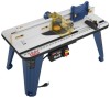
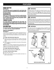
... Weight 28 lbs. VACUUM PORT FENCE ASSEMBLY INSERT PLATE ARTICULATING ROUTER CUTTER / BIT GUARD STARTING PIN 3 2 1 0 1 Inch FEATHER BOARD inch 3 2 1 0 1 Inch RESE T PUSH THROAT PLATES SWITCH ASSEMBLY RESET BUTTON MITER GAUGE Fig. 2 KNOW YOUR ROUTER TABLE See Figure 2. Before use of this product requires an understanding of the information on the...
... Weight 28 lbs. VACUUM PORT FENCE ASSEMBLY INSERT PLATE ARTICULATING ROUTER CUTTER / BIT GUARD STARTING PIN 3 2 1 0 1 Inch FEATHER BOARD inch 3 2 1 0 1 Inch RESE T PUSH THROAT PLATES SWITCH ASSEMBLY RESET BUTTON MITER GAUGE Fig. 2 KNOW YOUR ROUTER TABLE See Figure 2. Before use of this product requires an understanding of the information on the...
English Manual
Page 9
... small, use piloted cutters when using the starting pin for a guide and/or pivot point. STARTING PIN When you are included with a switch assembly that protects the electronic components of accidental starting when power returns. The throat plate provides a stable surface around the cutter and prevents objects... cause the workpiece to turn on the router table and plug the router table into a 120 volt grounded outlet. With the switch key inserted into the power source. VACUUM PORT The vacuum ports molded into the fence will prevent the tool from falling through the throat...
... small, use piloted cutters when using the starting pin for a guide and/or pivot point. STARTING PIN When you are included with a switch assembly that protects the electronic components of accidental starting when power returns. The throat plate provides a stable surface around the cutter and prevents objects... cause the workpiece to turn on the router table and plug the router table into a 120 volt grounded outlet. With the switch key inserted into the power source. VACUUM PORT The vacuum ports molded into the fence will prevent the tool from falling through the throat...

English Manual
Page 10
...guards must be securely in serious personal injury. 1 2 3 4 3 2 1 0 1 Inch 5 6 8 7 9 10 PACKING LIST 1. Table Leg Phillips Head Screw (16) 4. Switch Box 8. Carriage Bolt (2) 10. Under Table Guard (2) 18 DIFREEECDTION 23 19 22 3 20 3 2 1 0 1 Inch 17 21 16 15 14 13 12 11 Fig. 4 12....could result in .) (3) 15. Failure to possible serious personal injury. Router Insert Plate Screws (10-32 x 5/8 in serious personal injury. Switch Box Nut (3) 6. Fence Lock Knob Washer (2) 23. ASSEMBLY UNPACKING This product requires assembly. Carefully remove the product and any accessories ...
...guards must be securely in serious personal injury. 1 2 3 4 3 2 1 0 1 Inch 5 6 8 7 9 10 PACKING LIST 1. Table Leg Phillips Head Screw (16) 4. Switch Box 8. Carriage Bolt (2) 10. Under Table Guard (2) 18 DIFREEECDTION 23 19 22 3 20 3 2 1 0 1 Inch 17 21 16 15 14 13 12 11 Fig. 4 12....could result in .) (3) 15. Failure to possible serious personal injury. Router Insert Plate Screws (10-32 x 5/8 in serious personal injury. Switch Box Nut (3) 6. Fence Lock Knob Washer (2) 23. ASSEMBLY UNPACKING This product requires assembly. Carefully remove the product and any accessories ...
English Manual
Page 11
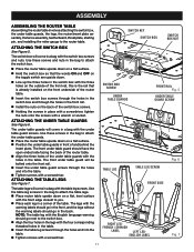
... and into the table. Tighten screws with a screwdriver. The table legs will come in a bag with the table leg screws. SWITCH KEY SWITCH BOX SWITCH BOX NUT SWITCH BOX SCREW UNDER TABLE GUARDS FRONT RAIL Fig. 5 UNDER TABLE GUARD SCREW TABLE LEG TABLE LEG SCREW Fig. 6 FRONT SIDE RIGHT LEG- ...warning should have the open ended side facing the back of the router table. Align the three holes of the table. ATTACHING THE SWITCH BOX See Figure 5. NOTE: The table leg with the holes in the bag to the router table. Use these screws in the table. ...
... and into the table. Tighten screws with a screwdriver. The table legs will come in a bag with the table leg screws. SWITCH KEY SWITCH BOX SWITCH BOX NUT SWITCH BOX SCREW UNDER TABLE GUARDS FRONT RAIL Fig. 5 UNDER TABLE GUARD SCREW TABLE LEG TABLE LEG SCREW Fig. 6 FRONT SIDE RIGHT LEG- ...warning should have the open ended side facing the back of the router table. Align the three holes of the table. ATTACHING THE SWITCH BOX See Figure 5. NOTE: The table leg with the holes in the bag to the router table. Use these screws in the table. ...
English Manual
Page 17
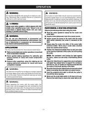
... the router is mounted on the table. Always plug the router into either of the router table switched outlets. Remove the switch key to inflict serious injury. To reduce the risk of serious personal injury, never connect the table mounted router into the ...; Reconfirm that could result in objects being thrown into your eyes resulting in use any attachments or accessories not recommended by the router table switched outlet. APPLICATIONS You may use . WARNING: When operating the router with the router table, the router must always be plugged into another power...
... the router is mounted on the table. Always plug the router into either of the router table switched outlets. Remove the switch key to inflict serious injury. To reduce the risk of serious personal injury, never connect the table mounted router into the ...; Reconfirm that could result in objects being thrown into your eyes resulting in use any attachments or accessories not recommended by the router table switched outlet. APPLICATIONS You may use . WARNING: When operating the router with the router table, the router must always be plugged into another power...
Repair Sheet
Page 3
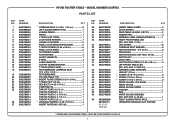
...LEFT FRONT TABLE LEG (INC. MAY BE PURCHASED LOCALLY 3 KEY NOS. 39-40 1 SWITCH KEY 1 DATA LABEL 1 * SWITCH BOX SCREW (1/4-20 x 5/8 in 3 FRONT RAIL 1 SWITCH BOX (INC. KEY NOS. 31 AND 43 1 WARNING LABEL (ENGLISH 1 HEX KEY (1/8...RING 4 LONG HINGE PIN 1 CUTTER GUARD BRACKET 1 T-TRACK (RIGHT SIDE 1 FEATHERBOARD CARRIAGE BOLT (1/4. MODEL NUMBER A25RT02 PARTS LIST DESCRIPTION QTY * CARRIAGE BOLT (1/4-20 x 1 3/4 in 6 LEFT SLIDING FENCE FACE 1 JOINING FENCE ... 9002780013 26 9002780054 27 9002780072 RYOBI ROUTER TABLE - KEY NOS. 6, 48-52 1 RIGHT SLIDING FENCE FACE...
...LEFT FRONT TABLE LEG (INC. MAY BE PURCHASED LOCALLY 3 KEY NOS. 39-40 1 SWITCH KEY 1 DATA LABEL 1 * SWITCH BOX SCREW (1/4-20 x 5/8 in 3 FRONT RAIL 1 SWITCH BOX (INC. KEY NOS. 31 AND 43 1 WARNING LABEL (ENGLISH 1 HEX KEY (1/8...RING 4 LONG HINGE PIN 1 CUTTER GUARD BRACKET 1 T-TRACK (RIGHT SIDE 1 FEATHERBOARD CARRIAGE BOLT (1/4. MODEL NUMBER A25RT02 PARTS LIST DESCRIPTION QTY * CARRIAGE BOLT (1/4-20 x 1 3/4 in 6 LEFT SLIDING FENCE FACE 1 JOINING FENCE ... 9002780013 26 9002780054 27 9002780072 RYOBI ROUTER TABLE - KEY NOS. 6, 48-52 1 RIGHT SLIDING FENCE FACE...


