
User Manual (English)
Page 3
.../Over Current Protection • Cable management • Power efficiency 80% (minimum) at full load Package contents • RF-700W PS2 power supply with connector cables • UL AC power cable • 4 screws • User Guide RF-700WPS2 3 Safety information The power supply meets safety UL EN60950 and FCC. Do not open the cover on...
.../Over Current Protection • Cable management • Power efficiency 80% (minimum) at full load Package contents • RF-700W PS2 power supply with connector cables • UL AC power cable • 4 screws • User Guide RF-700WPS2 3 Safety information The power supply meets safety UL EN60950 and FCC. Do not open the cover on...
User Manual (English)
Page 4
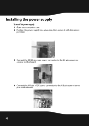
Installing the power supply To install the power supply: 1 Open your computer case. 2 Position the power supply into your case, then secure it with the screws provided. 3 Connect the 20/24-pin main power connector to the 24-pin connector on your motherboard. 4 Connect the 4/8-pin +12V power connector to the 4/8-pin connector on your motherboard. 4
Installing the power supply To install the power supply: 1 Open your computer case. 2 Position the power supply into your case, then secure it with the screws provided. 3 Connect the 20/24-pin main power connector to the 24-pin connector on your motherboard. 4 Connect the 4/8-pin +12V power connector to the 4/8-pin connector on your motherboard. 4

User Manual (English)
Page 5
5 Connect all of the following that apply to your computer: • The 4-pin peripheral device power connector to any peripheral device. • The floppy drive power connector to the floppy drive. • The Serial ATA connector to any hard drives that have a Serial ATA interface. RF-700WPS2 5
5 Connect all of the following that apply to your computer: • The 4-pin peripheral device power connector to any peripheral device. • The floppy drive power connector to the floppy drive. • The Serial ATA connector to any hard drives that have a Serial ATA interface. RF-700WPS2 5

User Manual (English)
Page 6
... the power cord is plugged into the power supply. • Make sure that the I/O switch is in the I position. • Make sure that all power connectors are connected to I. 9 Turn on your computer case. 7 Connect the power cord to the power supply. 8 Switch the I/O switch to the motherboard and devices correctly...
... the power cord is plugged into the power supply. • Make sure that the I/O switch is in the I position. • Make sure that all power connectors are connected to I. 9 Turn on your computer case. 7 Connect the power cord to the power supply. 8 Switch the I/O switch to the motherboard and devices correctly...
User Manual (English)
Page 9
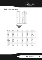
Main power connector Signal Color Pin Pin Color Signal +3.3 V Orange 1 13 Orange +3.3 V +3.3 V Orange 2 COM Black 3 +5 V Red 4 14 Blue -12 V 15 Black COM 16 Green PS_ON# COM Black 5 +5 V Red 6 COM Black 7 17 Black COM 18 Black COM 19 Black COM PWR ON Gray 8 20 N/C N/C +5 Vsb Purple 9 21 Red +5 V +12 DC Yellow 10 22 Red +5 V +12 DC Yellow 11 23 Red +5 V +3.3 V Orange 12 24 Black COM RF-700WPS2 9
Main power connector Signal Color Pin Pin Color Signal +3.3 V Orange 1 13 Orange +3.3 V +3.3 V Orange 2 COM Black 3 +5 V Red 4 14 Blue -12 V 15 Black COM 16 Green PS_ON# COM Black 5 +5 V Red 6 COM Black 7 17 Black COM 18 Black COM 19 Black COM PWR ON Gray 8 20 N/C N/C +5 Vsb Purple 9 21 Red +5 V +12 DC Yellow 10 22 Red +5 V +12 DC Yellow 11 23 Red +5 V +3.3 V Orange 12 24 Black COM RF-700WPS2 9