
Operation Manual
Page 3
... 25 feet or less in length. Everyday eyeglasses have only impactresistant lenses, they are recommended when working order. REMOVE ADJUSTING KEYS AND WRENCHES. When not in good working outdoors. Consult the operator's manual for which it will draw. Do not reach underneath work area. Do not ...and in use and reduce the risk of at all tools should be kept a safe distance from work or around or over the blade while blade is rotating. Cluttered areas and benches invite accidents. DO NOT leave tools or pieces of power and overheating. Make sure your hand and...
... 25 feet or less in length. Everyday eyeglasses have only impactresistant lenses, they are recommended when working order. REMOVE ADJUSTING KEYS AND WRENCHES. When not in good working outdoors. Consult the operator's manual for which it will draw. Do not reach underneath work area. Do not ...and in use and reduce the risk of at all tools should be kept a safe distance from work or around or over the blade while blade is rotating. Cluttered areas and benches invite accidents. DO NOT leave tools or pieces of power and overheating. Make sure your hand and...

Operation Manual
Page 9
Rating 120 V~, 15 Amps, 60 Hz No Load Speed 4,400 r/min. (RPM) RIVING KNIFE ANTI-KICKBACK PAWLS BLADE GUARD ASSEMBLY SAW BLADE MITER GAUGE RIP FENCE MICRO-ADJUST WHEEL LOCKING LEVER FRONT RAIL BLADE WRENCHES BEVEL SCALE GRIPS BLADE AND BLADE WRENCH STORAGE LEG STAND BEVEL LOCKING LEVER SWITCH ASSEMBLY BEVEL ADJUSTING HANDWHEEL BEVEL INDICATOR HEIGHT ADJUSTING KNOB BLADE HEIGHT LOCK KNOB Fig. 3 9 Cutting Depth at 45 2-1/2 in . Cutting Depth at 90 3-1/2 in . FEATURES PRODUCT SPECIFICATIONS Blade Diameter 10 in . Blade Arbor 5/8 in .
Rating 120 V~, 15 Amps, 60 Hz No Load Speed 4,400 r/min. (RPM) RIVING KNIFE ANTI-KICKBACK PAWLS BLADE GUARD ASSEMBLY SAW BLADE MITER GAUGE RIP FENCE MICRO-ADJUST WHEEL LOCKING LEVER FRONT RAIL BLADE WRENCHES BEVEL SCALE GRIPS BLADE AND BLADE WRENCH STORAGE LEG STAND BEVEL LOCKING LEVER SWITCH ASSEMBLY BEVEL ADJUSTING HANDWHEEL BEVEL INDICATOR HEIGHT ADJUSTING KNOB BLADE HEIGHT LOCK KNOB Fig. 3 9 Cutting Depth at 45 2-1/2 in . Cutting Depth at 90 3-1/2 in . FEATURES PRODUCT SPECIFICATIONS Blade Diameter 10 in . Blade Arbor 5/8 in .

Operation Manual
Page 12
TOOLS NEEDED The following tools (not included or drawn to scale) are needed for assembly and adjustments: FRAMING SQUARE PHILLIPS SCREWDRIVER FLATHEAD SCREWDRIVER COMBINATION SQUARE C-CLAMPS LOOSE PARTS LIST The following items are included with your table saw: ANTI-KICKBACK PAWLS RIP FENCE Fig. 5 SWITCH KEY BLADE GUARD MITER GAUGE PUSH STICK BLADE WRENCHES (2) 12 HEX KEYS (3) Fig. 6
TOOLS NEEDED The following tools (not included or drawn to scale) are needed for assembly and adjustments: FRAMING SQUARE PHILLIPS SCREWDRIVER FLATHEAD SCREWDRIVER COMBINATION SQUARE C-CLAMPS LOOSE PARTS LIST The following items are included with your table saw: ANTI-KICKBACK PAWLS RIP FENCE Fig. 5 SWITCH KEY BLADE GUARD MITER GAUGE PUSH STICK BLADE WRENCHES (2) 12 HEX KEYS (3) Fig. 6

Operation Manual
Page 18
... See Figures 14 - 15. These accessories must be securely stored prior to side. WING NUT PUSH STICK LEVELING FOOT BLADE BLADE WRENCHES WING NUT MITER GAUGE Fig. 13 ANTI-KICKBACK PAWLS ANTI-KICKBACK PAWLS / BLADE GUARD STORAGE BLADE GUARD Fig. 14 18 RIP FENCE Fig. 15 ASSEMBLY TO SECURE/LEVEL THE SAW See Figure 13.
... See Figures 14 - 15. These accessories must be securely stored prior to side. WING NUT PUSH STICK LEVELING FOOT BLADE BLADE WRENCHES WING NUT MITER GAUGE Fig. 13 ANTI-KICKBACK PAWLS ANTI-KICKBACK PAWLS / BLADE GUARD STORAGE BLADE GUARD Fig. 14 18 RIP FENCE Fig. 15 ASSEMBLY TO SECURE/LEVEL THE SAW See Figure 13.

Operation Manual
Page 21
... stop a kickback increasing the risk of the saw. kickback pawls. Holding both wrenches firmly, push the right wrench to make sure pawls are securely locked. 21 BLADE WRENCH (LEFT) HANDLE ANTI-KICKBACK PAWLS BLADE GUARD BLADE WRENCH (RIGHT) SET SCREW HEX NUT BUTTON Fig. 22 GUARD LEVER WARNING: Replace...the back of serious personal injury. To tighten the blade: Using the left side) to the saw blade, the saw . Holding both wrenches firmly, pull the outside wrench (right side) forward while pushing the inside (left blade wrench, insert the open end onto the flats on the...
... stop a kickback increasing the risk of the saw. kickback pawls. Holding both wrenches firmly, push the right wrench to make sure pawls are securely locked. 21 BLADE WRENCH (LEFT) HANDLE ANTI-KICKBACK PAWLS BLADE GUARD BLADE WRENCH (RIGHT) SET SCREW HEX NUT BUTTON Fig. 22 GUARD LEVER WARNING: Replace...the back of serious personal injury. To tighten the blade: Using the left side) to the saw blade, the saw . Holding both wrenches firmly, pull the outside wrench (right side) forward while pushing the inside (left blade wrench, insert the open end onto the flats on the...
Operation Manual
Page 38
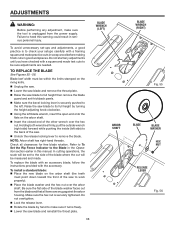
... to its full height by hand to remove the blade. Check all items are needed. To replace the blade with an accessory blade, follow the instructions provided with the accessory. Raise the saw blade and reinstall the throat plate. 38 BLADE WRENCH (LEFT) ARBOR SHAFT BLADE WRENCH (RIGHT) Fig. 55 BLADE BLADE WASHER HEX NUT RELEASE LEVER Fig. 56 Refer...
... to its full height by hand to remove the blade. Check all items are needed. To replace the blade with an accessory blade, follow the instructions provided with the accessory. Raise the saw blade and reinstall the throat plate. 38 BLADE WRENCH (LEFT) ARBOR SHAFT BLADE WRENCH (RIGHT) Fig. 55 BLADE BLADE WASHER HEX NUT RELEASE LEVER Fig. 56 Refer...

Operation Manual
Page 40
...even with the top of the 0º stop screw at 0º and plus or minus 45º with a wrench. Place a 90º square against the stop screws. Check again for squareness and readjust if needed....to rotate miter gauge base past stop screws. Loosen the lock nut of the saw blade starts to move. NOTE: The miter gauge provides close tolerances, test cuts are recommended. If the...STOP SCREW LOCK NUT FLAT HEAD SCREW STOP PIN Fig. 61 SET SCREW 40 Fig. 62 ADJUSTMENTS If blade is not 45º to the table: Loosen 45º stop screw until the saw ...
...even with the top of the 0º stop screw at 0º and plus or minus 45º with a wrench. Place a 90º square against the stop screws. Check again for squareness and readjust if needed....to rotate miter gauge base past stop screws. Loosen the lock nut of the saw blade starts to move. NOTE: The miter gauge provides close tolerances, test cuts are recommended. If the...STOP SCREW LOCK NUT FLAT HEAD SCREW STOP PIN Fig. 61 SET SCREW 40 Fig. 62 ADJUSTMENTS If blade is not 45º to the table: Loosen 45º stop screw until the saw ...


