
English Manual
Page 1
... this manual for reference. MST Sat. 8 a.m.-4 p.m. Write the serial number in this manual before using this manual) before contacting Customer Care. MST ON THE WEB: www.reebokservice.com CAUTION Read all precautions and instructions in the space above for future reference. USERʼS MANUAL please contact Customer Care. IMPORTANT: Please register this product (see the limited warranty on the back cover of this...
... this manual for reference. MST Sat. 8 a.m.-4 p.m. Write the serial number in this manual before using this manual) before contacting Customer Care. MST ON THE WEB: www.reebokservice.com CAUTION Read all precautions and instructions in the space above for future reference. USERʼS MANUAL please contact Customer Care. IMPORTANT: Please register this product (see the limited warranty on the back cover of this...
English Manual
Page 2
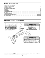
... manual and request a free replacement decal. Note: The decal(s) may not be shown at actual size. This product is missing or illegible, see the front cover of Reebok. Apply the decal in the location shown. TABLE OF CONTENTS WARNING DECAL PLACEMENT 2 IMPORTANT PRECAUTIONS 3 BEFORE YOU BEGIN 4 PART IDENTIFICATION CHART 5 ASSEMBLY 6 ADJUSTMENT 11 EXERCISE GUIDELINES 13 PART LIST 14 EXPLODED DRAWING 15 ORDERING REPLACEMENT PARTS Back Cover LIMITED WARRANTY Back Cover...
... manual and request a free replacement decal. Note: The decal(s) may not be shown at actual size. This product is missing or illegible, see the front cover of Reebok. Apply the decal in the location shown. TABLE OF CONTENTS WARNING DECAL PLACEMENT 2 IMPORTANT PRECAUTIONS 3 BEFORE YOU BEGIN 4 PART IDENTIFICATION CHART 5 ASSEMBLY 6 ADJUSTMENT 11 EXERCISE GUIDELINES 13 PART LIST 14 EXPLODED DRAWING 15 ORDERING REPLACEMENT PARTS Back Cover LIMITED WARRANTY Back Cover...
English Manual
Page 3
... clearance around the weight bench to mount, dismount, and use a barbell that is designed to ensure that the pins on the backrest support are using the leg lever, place a barbell with the same amount of this manual and all instructions in this manual. 3. Make sure that the adjustment knobs are inserted into the weight rests and are performing bench press exercises, your physician. The weight bench is especially...
... clearance around the weight bench to mount, dismount, and use a barbell that is designed to ensure that the pins on the backrest support are using the leg lever, place a barbell with the same amount of this manual and all instructions in this manual. 3. Make sure that the adjustment knobs are inserted into the weight rests and are performing bench press exercises, your physician. The weight bench is especially...
English Manual
Page 4
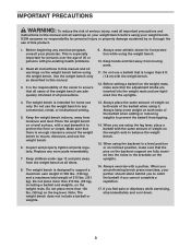
... location of the serial number decal are labeled. If you , note the product model number and serial number before using the weight bench. Whether your goal is to tone your body, build dramatic muscle size and strength, or improve your benefit, read this manual. ASSEMBLED DIMENSIONS: Height: 4 ft. 6 in. (137 cm) Width: 3 ft. 7 in. (109 cm) Depth: 5 ft. 5 in. (165 cm) Adjustment Knob Backrest Seat Leg Lever Weight Rest Backrest Support Upright Weight...
... location of the serial number decal are labeled. If you , note the product model number and serial number before using the weight bench. Whether your goal is to tone your body, build dramatic muscle size and strength, or improve your benefit, read this manual. ASSEMBLED DIMENSIONS: Height: 4 ft. 6 in. (137 cm) Width: 3 ft. 7 in. (109 cm) Depth: 5 ft. 5 in. (165 cm) Adjustment Knob Backrest Seat Leg Lever Weight Rest Backrest Support Upright Weight...
English Manual
Page 5
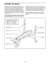
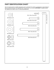
M10 x 190mm Bolt (24) M6 Washer (29) M8 Washer (28) M10 Washer (40) M8 Locknut (27) M4 x 16mm Screw (25) M6 x 35mm Screw (26) M8 x 60mm Bolt (33) M8 x 70mm Bolt (30) M8 x 80mm Bolt (31) M10 Locknut (32) 5 IMPORTANT: If a part is not in the hardware kit, check to identify small parts used in parentheses by each drawing is the key number of the part, from the PART LIST near the end of this manual. PART IDENTIFICATION CHART See the drawings below to see if it has been preattached. The number in assembly.
M10 x 190mm Bolt (24) M6 Washer (29) M8 Washer (28) M10 Washer (40) M8 Locknut (27) M4 x 16mm Screw (25) M6 x 35mm Screw (26) M8 x 60mm Bolt (33) M8 x 70mm Bolt (30) M8 x 80mm Bolt (31) M10 Locknut (32) 5 IMPORTANT: If a part is not in the hardware kit, check to identify small parts used in parentheses by each drawing is the key number of the part, from the PART LIST near the end of this manual. PART IDENTIFICATION CHART See the drawings below to see if it has been preattached. The number in assembly.
English Manual
Page 6
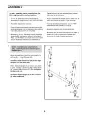
... a set of its size, the weight bench should be assembled in the location where it to the Left Upright (1) with two M8 x 80mm Bolts (31) and two M8 Locknuts (27). Do not tighten the Locknuts yet. Do not dispose of the packing materials until assembly is enough clearance to walk around the weight bench as you assemble it. • Tighten all parts as you assemble them, unless instructed...
... a set of its size, the weight bench should be assembled in the location where it to the Left Upright (1) with two M8 x 80mm Bolts (31) and two M8 Locknuts (27). Do not tighten the Locknuts yet. Do not dispose of the packing materials until assembly is enough clearance to walk around the weight bench as you assemble it. • Tighten all parts as you assemble them, unless instructed...
English Manual
Page 7
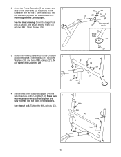
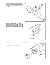
...tighten the Locknuts yet. 2 5 28 31 28 25 31 28 27 27 4. 2. Orient the Frame Extension (5) as shown, and attach it onto the Frame (3). Make sure 4 that the pins on the Backrest Support are fully inserted into the holes in a set of brackets on the Uprights (1, 4). See steps 1 to the Crossbar 3 (2) with two M8 x 70mm Bolts...(19) as shown, and 2 slide it to the Frame (3) with two M4 x 16mm Screws (25). 30 30 3 28 28 5 27 Hexagonal Holes 3 Wide Side 19 3. Attach the Frame Extension with three M8 x 80mm Bolts (31), three M8 Washers (28), and three M8 Locknuts (27).
...tighten the Locknuts yet. 2 5 28 31 28 25 31 28 27 27 4. 2. Orient the Frame Extension (5) as shown, and attach it onto the Frame (3). Make sure 4 that the pins on the Backrest Support are fully inserted into the holes in a set of brackets on the Uprights (1, 4). See steps 1 to the Crossbar 3 (2) with two M8 x 70mm Bolts...(19) as shown, and 2 slide it to the Frame (3) with two M4 x 16mm Screws (25). 30 30 3 28 28 5 27 Hexagonal Holes 3 Wide Side 19 3. Attach the Frame Extension with three M8 x 80mm Bolts (31), three M8 Washers (28), and three M8 Locknuts (27).
English Manual
Page 8
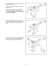
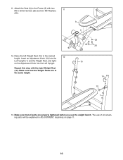
5. Grease Attach the Leg Lever (6) to an M8 x 27 31 80mm Bolt (31). the Leg Lever must pivot easily. 16 3 25 6. Do not overtighten the Locknut; Insert the Weight Tube (11) into the Frame (3). Insert a Pad Tube (12) into the Leg Lever 6 (6). Then, press two Pad Caps (37) into the Pad Tube. ...7 37 13 3 12 13 37 8 Slide two Foam Pads (13) onto the Pad Tube. Attach the Weight Tube with 6 the M8 x 80mm Bolt (31) and an M8 Locknut (27). Attach the Bumper (16) to the Frame (3) with an M4 x 16mm Screw...
5. Grease Attach the Leg Lever (6) to an M8 x 27 31 80mm Bolt (31). the Leg Lever must pivot easily. 16 3 25 6. Do not overtighten the Locknut; Insert the Weight Tube (11) into the Frame (3). Insert a Pad Tube (12) into the Leg Lever 6 (6). Then, press two Pad Caps (37) into the Pad Tube. ...7 37 13 3 12 13 37 8 Slide two Foam Pads (13) onto the Pad Tube. Attach the Weight Tube with 6 the M8 x 80mm Bolt (31) and an M8 Locknut (27). Attach the Bumper (16) to the Frame (3) with an M4 x 16mm Screw...
English Manual
Page 9
... 37 12 37 13 9. Attach the Backrest Frames to an M10 x 190mm Bolt (24). Tighten the M6 x 35mm Screws (26). 10 32 40 7 3 29 29 26 40 Grease 24 9 Orient the Backrest Frames (7) as shown. Then, press two Pad Caps (37) into the Leg Lever (6). Apply grease to the Backrest (8) 9... with the M10 x 190mm Bolt (24), two M10 Washers (40), and an M10 Locknut (32). Insert two Pad Tubes (12) into each Pad 8 Tube. See step 9. Do not overtighten the Locknut; Do not tighten the Screws yet....
... 37 12 37 13 9. Attach the Backrest Frames to an M10 x 190mm Bolt (24). Tighten the M6 x 35mm Screws (26). 10 32 40 7 3 29 29 26 40 Grease 24 9 Orient the Backrest Frames (7) as shown. Then, press two Pad Caps (37) into the Leg Lever (6). Apply grease to the Backrest (8) 9... with the M10 x 190mm Bolt (24), two M10 Washers (40), and an M10 Locknut (32). Insert two Pad Tubes (12) into each Pad 8 Tube. See step 9. Do not overtighten the Locknut; Do not tighten the Screws yet....
English Manual
Page 10
Make sure that the Weight Rests are properly tightened before you use of all parts are at the same height. 9 3 29 29 26 15 15 10 1 13. en the Adjustment Knob into the 12 Left Upright (1) and the Weight Rest, and tight- The use the weight bench. Attach the Seat (9) to the desired height. Repeat this step with two M6 x 35mm Screws (26) and two M6...
Make sure that the Weight Rests are properly tightened before you use of all parts are at the same height. 9 3 29 29 26 15 15 10 1 13. en the Adjustment Knob into the 12 Left Upright (1) and the Weight Rest, and tight- The use the weight bench. Attach the Seat (9) to the desired height. Repeat this step with two M6 x 35mm Screws (26) and two M6...
English Manual
Page 11
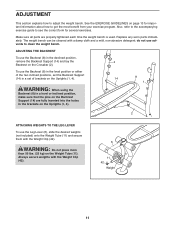
... two inclined positions, set the Backrest Support (14) in a set of brackets on the Uprights (1, 4). 14 8 1 WARNING: When using the Backrest (8) in a level or inclined position, make sure that the pins on the Backrest Support (14) are properly tightened each time the weight bench is used. Replace any worn parts immediately. Also, refer to the accompanying exercise guide to get the most benefit from your exercise program. See the EXERCISE...
... two inclined positions, set the Backrest Support (14) in a set of brackets on the Uprights (1, 4). 14 8 1 WARNING: When using the Backrest (8) in a level or inclined position, make sure that the pins on the Backrest Support (14) are properly tightened each time the weight bench is used. Replace any worn parts immediately. Also, refer to the accompanying exercise guide to get the most benefit from your exercise program. See the EXERCISE...
English Manual
Page 12
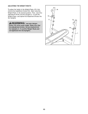
ADJUSTING THE WEIGHT RESTS To adjust the height of the Weight Rests (15), first 15 remove the Adjustment Knobs (10). Then, insert the Adjustment Knobs into the Uprights (1, 4) and the Weight Rests, and tighten the Adjustment Knobs into the Uprights. 15 10 1 12 Make sure that the Adjustment Knobs (10) are inserted into the Uprights (1, 4) and the Weight Rests and are tightened into 10 the Uprights. 4 WARNING: Set both Weight Rests (15) at the same height. Next, raise the Weight Rests to the desired position.
ADJUSTING THE WEIGHT RESTS To adjust the height of the Weight Rests (15), first 15 remove the Adjustment Knobs (10). Then, insert the Adjustment Knobs into the Uprights (1, 4) and the Weight Rests, and tighten the Adjustment Knobs into the Uprights. 15 10 1 12 Make sure that the Adjustment Knobs (10) are inserted into the Uprights (1, 4) and the Weight Rests and are tightened into 10 the Uprights. 4 WARNING: Set both Weight Rests (15) at the same height. Next, raise the Weight Rests to the desired position.

English Manual
Page 13
... their capacity. Weight Loss-To lose weight, use a low amount of resistance and increase the number of rest. Use your body time to regenerate. Select a moderate amount of resistance and increase the number of repetitions in each set " is a series of motion for exercise. Perform the repetitions in each set . workout, and the numbers of repetitions and sets to determine the appropriate length of time for each EXERCISE FORM Move...
... their capacity. Weight Loss-To lose weight, use a low amount of resistance and increase the number of rest. Use your body time to regenerate. Select a moderate amount of resistance and increase the number of repetitions in each set " is a series of motion for exercise. Perform the repetitions in each set . workout, and the numbers of repetitions and sets to determine the appropriate length of time for each EXERCISE FORM Move...
English Manual
Page 14
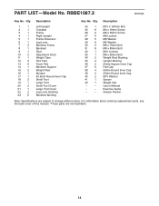
... 6 38 4 39 2 40 2 41 1 42 1 * - * - * - For information about ordering replacement parts, see the back cover of this manual. *These parts are subject to change without notice. PART LIST-Model No. Description M10 x 190mm Bolt M4 x 16mm Screw M6 x 35mm Screw M8 Locknut M8 Washer M6 Washer M8 x 70mm Bolt M8 x 80mm Bolt M10 Locknut M8 x 60mm Bolt Weight Rest Bushing Upright Bushing 25mm Square Inner Cap Pad Cap...
... 6 38 4 39 2 40 2 41 1 42 1 * - * - * - For information about ordering replacement parts, see the back cover of this manual. *These parts are subject to change without notice. PART LIST-Model No. Description M10 x 190mm Bolt M4 x 16mm Screw M6 x 35mm Screw M8 Locknut M8 Washer M6 Washer M8 x 70mm Bolt M8 x 80mm Bolt M10 Locknut M8 x 60mm Bolt Weight Rest Bushing Upright Bushing 25mm Square Inner Cap Pad Cap...
English Manual
Page 15
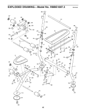
RBBE1087.2 R0709A 38 37 13 22 6 37 27 41 38 13 11 39 42 38 12 22 39 33 25 34 10 15 25 35 14 8 38 15 36 9 37 17 13 31 27 25 16 37 4 7 13 27 37 32 40 23 18 3 23 40 24 29 29 26 12 23 31 26 2 20 30 31 28 5 25 27 28 31 28 13 19 37 21 26 29 25 29 35 34 10 31 28 27 31 27 31 18 20 25 1 27 25 25 15 EXPLODED DRAWING-Model No.
RBBE1087.2 R0709A 38 37 13 22 6 37 27 41 38 13 11 39 42 38 12 22 39 33 25 34 10 15 25 35 14 8 38 15 36 9 37 17 13 31 27 25 16 37 4 7 13 27 37 32 40 23 18 3 23 40 24 29 29 26 12 23 31 26 2 20 30 31 28 5 25 27 28 31 28 13 19 37 21 26 29 25 29 35 34 10 31 28 27 31 27 31 18 20 25 1 27 25 25 15 EXPLODED DRAWING-Model No.
English Manual
Page 16
... the front cover of this manual) • the key number and description of the replacement part(s) (see the front cover of the product; to the original purchaser. ICON is under warranty. ICON Health & Fitness, Inc., 1500 S. 1000 W., Logan, UT 84321-9813 Part No. 283802 R0709A Printed in connection with the use , or costs of removal or installation; This warranty extends only to products used for which warranty claims are limited in...
... the front cover of this manual) • the key number and description of the replacement part(s) (see the front cover of the product; to the original purchaser. ICON is under warranty. ICON Health & Fitness, Inc., 1500 S. 1000 W., Logan, UT 84321-9813 Part No. 283802 R0709A Printed in connection with the use , or costs of removal or installation; This warranty extends only to products used for which warranty claims are limited in...


