
MLM82S Data Sheet
Page 1
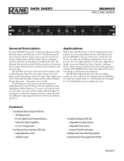
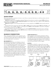
... mix amplifiers feature independent overload indicators. The Mic/Line Assign switches and independent Mono switches for Line operation. A and B Output Level controls set for each of the Stereo Line Inputs make the MLM82S a true, dual zone capable mixer, i.e., the Outputs may also be thought of as sub-mixing, recording and post-production. The factory default is ideal for Mic level output • Individual Level Control Hole Plugs Included • Internal Universal Power Supply (100-240 VAC) Data Sheet-1 DATA SHEET MLM82S MIC/LINE MIXER General Description The Rane MLM82S...
... mix amplifiers feature independent overload indicators. The Mic/Line Assign switches and independent Mono switches for Line operation. A and B Output Level controls set for each of the Stereo Line Inputs make the MLM82S a true, dual zone capable mixer, i.e., the Outputs may also be thought of as sub-mixing, recording and post-production. The factory default is ideal for Mic level output • Individual Level Control Hole Plugs Included • Internal Universal Power Supply (100-240 VAC) Data Sheet-1 DATA SHEET MLM82S MIC/LINE MIXER General Description The Rane MLM82S...
MLM82S Data Sheet
Page 2
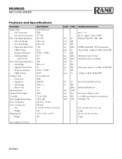
MLM82S MIC/LINE MIXER Features and Specifications Parameter Inputs: Type ..........Mic Connectors ..........Stereo Line Connectors Mic / Line Input Impedance ..........Mic Gain Range ..........Line Gain Range ..........Equivalent Input Noise ..........THD & Noise ..........Frequency Response ..........Maximum Input .....@ Mic Level Stereo Line Input Impedance ..........Gain Range ..........Signal-To-Noise Ratio ..........Frequency Response ..........THD & Noise Outputs: Type ..........Connectors ..........Impedance ..........Gain Range ..........Drive Level Phantom Power Output Cable Length ...
MLM82S MIC/LINE MIXER Features and Specifications Parameter Inputs: Type ..........Mic Connectors ..........Stereo Line Connectors Mic / Line Input Impedance ..........Mic Gain Range ..........Line Gain Range ..........Equivalent Input Noise ..........THD & Noise ..........Frequency Response ..........Maximum Input .....@ Mic Level Stereo Line Input Impedance ..........Gain Range ..........Signal-To-Noise Ratio ..........Frequency Response ..........THD & Noise Outputs: Type ..........Connectors ..........Impedance ..........Gain Range ..........Drive Level Phantom Power Output Cable Length ...
MLM82S Data Sheet
Page 4
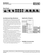
... Specifications The mixer shall have four studio-grade mono mic/line inputs each with position indicators. In addition, each of the front panel level control knobs may be capable of operation by means of the phantom power and line switches on the rear panel, recessed assign switches, internally located pad switch for dual mono operation with ¼" TRS input jack, level control and pre-level control mono switch. Application Diagram MIC MIC MIC MIC 4321 MLM 82S IN 1 IN 2 IN 3 A / A+B / B IN 4 CD L R DVD L R STEREO / AMPLIFIER VHS MONO L OR R MAIN MIXER MIC / LINE...
... Specifications The mixer shall have four studio-grade mono mic/line inputs each with position indicators. In addition, each of the front panel level control knobs may be capable of operation by means of the phantom power and line switches on the rear panel, recessed assign switches, internally located pad switch for dual mono operation with ¼" TRS input jack, level control and pre-level control mono switch. Application Diagram MIC MIC MIC MIC 4321 MLM 82S IN 1 IN 2 IN 3 A / A+B / B IN 4 CD L R DVD L R STEREO / AMPLIFIER VHS MONO L OR R MAIN MIXER MIC / LINE...
MLM82S Manual
Page 2
... such as power supply cord or plug is the AC mains disconnect device and must remain readily operable. Heed all instructions. 5. Follow all warnings. 4. A grounding-type plug has two blades and a third grounding prong. This symbol indicates that warn of this equipment does cause harmful interference to radio or television reception, which the receiver is used in a residential installation. These...
... such as power supply cord or plug is the AC mains disconnect device and must remain readily operable. Heed all instructions. 5. Follow all warnings. 4. A grounding-type plug has two blades and a third grounding prong. This symbol indicates that warn of this equipment does cause harmful interference to radio or television reception, which the receiver is used in a residential installation. These...
MLM82S Manual
Page 4
... to ground. A single phantom power switch is provided for those in a rush. Stereo Inputs use two-conductor-plus-shielded wire, even for inputs. The same wiring conventions as possible without damage to A, B or A+B outputs using the front panel ASSIGN switches. If the MLM82S is LINE. Manual-1 Each microphone input may be assigned to your fragile speakers, ears and nerves. Choose between the two is connected to the MIC/LINE INPUT JACKS. OPERATORS MANUAL MLM82S MIC/LINE MIXER 1 4 6 2 8 0 10 A+B SIG / OL LEVEL ASSIGN MONO MIC / LINE INPUTS...
... to ground. A single phantom power switch is provided for those in a rush. Stereo Inputs use two-conductor-plus-shielded wire, even for inputs. The same wiring conventions as possible without damage to A, B or A+B outputs using the front panel ASSIGN switches. If the MLM82S is LINE. Manual-1 Each microphone input may be assigned to your fragile speakers, ears and nerves. Choose between the two is connected to the MIC/LINE INPUT JACKS. OPERATORS MANUAL MLM82S MIC/LINE MIXER 1 4 6 2 8 0 10 A+B SIG / OL LEVEL ASSIGN MONO MIC / LINE INPUTS...
MLM82S Manual
Page 5
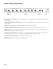
... problem-causing individual Input Level may be assigned to the A, A+B, B Outputs. 3 ASSIGN switches determine between the A, A+B or B Outputs for a -30 dBu signal, and turns red when the Input is applied to the Outputs. 5 MONO switch mixes the A and B sides of an approaching overload condition. When active, the associated LED lights, and the A and B Inputs for that channel have exactly the same level. 6 OUTPUT OverLoad LED illuminates within 3 dB of clipping. 2 MONO MIC/LINE INPUT LEVEL controls...
... problem-causing individual Input Level may be assigned to the A, A+B, B Outputs. 3 ASSIGN switches determine between the A, A+B or B Outputs for a -30 dBu signal, and turns red when the Input is applied to the Outputs. 5 MONO switch mixes the A and B sides of an approaching overload condition. When active, the associated LED lights, and the A and B Inputs for that channel have exactly the same level. 6 OUTPUT OverLoad LED illuminates within 3 dB of clipping. 2 MONO MIC/LINE INPUT LEVEL controls...
MLM82S Manual
Page 6
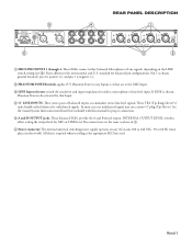
...cord. Manual-3 These TRS (Tip-Ring-Sleeve) ¼" jacks handle either balanced Microphone or Line signals, depending on any Inputs 1-4 that are the same as above in 1. 6 Power connector: The internal universal switching power supply operates on the LINE switch setting (see 3). AUDIO EQUIPMENT 100-240 V 24TJ 50/60 Hz 7 WATTS R BALANCED: PIN 3 = (-), PIN 2 = (+), PIN 1 = (G) B A ACN 001 345 482 OUTPUTS 6 REAR PANEL DESCRIPTION 4 A A A 8 7 6 B B B LINE INPUTS A 5 4 B LINE 1 3 2 1 LINE LINE LINE MIC / LINE INPUTS 3 15V PHANTOM POWER 2 1 MIC/LINE INPUTS...
...cord. Manual-3 These TRS (Tip-Ring-Sleeve) ¼" jacks handle either balanced Microphone or Line signals, depending on any Inputs 1-4 that are the same as above in 1. 6 Power connector: The internal universal switching power supply operates on the LINE switch setting (see 3). AUDIO EQUIPMENT 100-240 V 24TJ 50/60 Hz 7 WATTS R BALANCED: PIN 3 = (-), PIN 2 = (+), PIN 1 = (G) B A ACN 001 345 482 OUTPUTS 6 REAR PANEL DESCRIPTION 4 A A A 8 7 6 B B B LINE INPUTS A 5 4 B LINE 1 3 2 1 LINE LINE LINE MIC / LINE INPUTS 3 15V PHANTOM POWER 2 1 MIC/LINE INPUTS...
MLM82S Manual
Page 7
..., Phantom Power is sufficient power for all Inputs selected for microphone use a Rane SC 1.7 Security Cover. B. The Mic needs Phantom Power (See Rear Panel, 2). STEREO LINE LEVEL INPUTS 5-8 The STEREO LINE INPUT LEVEL controls adjust both the input dynamic range and mix level. A single mono input may be used for mono operation. A red glowing LED indicates that the levels are set for the A and/or B inputs. Switch the Input to clipping is off , and snap in one or two mono sources to go to both A and B outputs...
..., Phantom Power is sufficient power for all Inputs selected for microphone use a Rane SC 1.7 Security Cover. B. The Mic needs Phantom Power (See Rear Panel, 2). STEREO LINE LEVEL INPUTS 5-8 The STEREO LINE INPUT LEVEL controls adjust both the input dynamic range and mix level. A single mono input may be used for mono operation. A red glowing LED indicates that the levels are set for the A and/or B inputs. Switch the Input to clipping is off , and snap in one or two mono sources to go to both A and B outputs...
MLM82S Schematic
Page 2
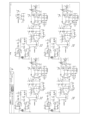
...RED R263 10.0k PH PWR R92 R239 R240 2.49k 2.49k 2.49k R264 10.0k MIC 4 INPUT J15 -+ 2 3 1 2200pF Z7 4 S4B 5 6 2P2T MIC/LINE GND D48 D49 1SMB15CAT3 -15 GND Z8 2200pF 3 S4A 2 1 2P2T 7 S4C 8...R250 + C82 S13C 7 8 2P2T GND 100 R251 100 S13B S13A 4 2P2T 1 5 2 6 3 PHANTOM GND POWER 470/25v GND PH PWR MBR0540T1G R99 D22 5 072 6 U3B 7 100k C91 0.1 R108 1.10M GND ...001 10.0k 1/11/2012 C:\CAD Projects\MLM82S\MLM82S-1.SchDoc Main ACTION: ECN 114570 RI TO SMT CONVERSION DRAWN BY: CHECKED BY: MIC INPUTS MLM82S 10802 47th Avenue West SHEET: Mukilteo WA 98275-5098 1 of 3...
...RED R263 10.0k PH PWR R92 R239 R240 2.49k 2.49k 2.49k R264 10.0k MIC 4 INPUT J15 -+ 2 3 1 2200pF Z7 4 S4B 5 6 2P2T MIC/LINE GND D48 D49 1SMB15CAT3 -15 GND Z8 2200pF 3 S4A 2 1 2P2T 7 S4C 8...R250 + C82 S13C 7 8 2P2T GND 100 R251 100 S13B S13A 4 2P2T 1 5 2 6 3 PHANTOM GND POWER 470/25v GND PH PWR MBR0540T1G R99 D22 5 072 6 U3B 7 100k C91 0.1 R108 1.10M GND ...001 10.0k 1/11/2012 C:\CAD Projects\MLM82S\MLM82S-1.SchDoc Main ACTION: ECN 114570 RI TO SMT CONVERSION DRAWN BY: CHECKED BY: MIC INPUTS MLM82S 10802 47th Avenue West SHEET: Mukilteo WA 98275-5098 1 of 3...
MLM82S Schematic
Page 3
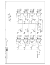
... 2P2T R26 3 2 1 10.0k GND 5 6 U7B 7 4580 R158 C72 511 22/16v 3 R7A 210kA R30 11.3k 1 R27 10.0k GND LINE 8 MONO S8A 2P2T R31 3 2 1 10.0k GND 5 6 U8B 7 R159 C73 511 22/16v 4580 3 R8A 210kA R35 11.3k 1 R32 10.0k GND C106 ...4 GND C105 47pF R164 47.5k 6 4580 5 U9B 7 GND LINE MIX_B 1/11/2012 C:\CAD Projects\MLM82S\MLM82S-2.SchDoc +15 GND C4 C5 C6 C7 C8 0.1 0.1 0.1 0.1 0.1 C53 C54 C55 C56 C57 0.1 0.1 0.1 0.1 0.1 -15 Main ACTION: ECN 114570 RI TO SMT CONVERSION DRAWN BY: CHECKED BY: LINE INPUTS MLM82S 10802 47th Avenue West SHEET: Mukilteo WA 98275-5098 2 of...
... 2P2T R26 3 2 1 10.0k GND 5 6 U7B 7 4580 R158 C72 511 22/16v 3 R7A 210kA R30 11.3k 1 R27 10.0k GND LINE 8 MONO S8A 2P2T R31 3 2 1 10.0k GND 5 6 U8B 7 R159 C73 511 22/16v 4580 3 R8A 210kA R35 11.3k 1 R32 10.0k GND C106 ...4 GND C105 47pF R164 47.5k 6 4580 5 U9B 7 GND LINE MIX_B 1/11/2012 C:\CAD Projects\MLM82S\MLM82S-2.SchDoc +15 GND C4 C5 C6 C7 C8 0.1 0.1 0.1 0.1 0.1 C53 C54 C55 C56 C57 0.1 0.1 0.1 0.1 0.1 -15 Main ACTION: ECN 114570 RI TO SMT CONVERSION DRAWN BY: CHECKED BY: LINE INPUTS MLM82S 10802 47th Avenue West SHEET: Mukilteo WA 98275-5098 2 of...
MLM82S Schematic
Page 4
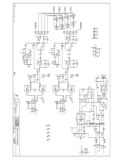
10 9 10 9 10 S9C S10C S11C S12C 2P3T 2P3T 2P3T 2P3T GND 9 10 +15 GND C1 C2 C3 0.1 0.1 0.1 C65 C64 C87 0.1 0.1 0.1 -15 9 LINE MIX_A MIC 1 MIC 2 MIC 3 MIC 4 S9A 4 2P3T S9B 2P3T 18 5 6 7 2 3 S10A 4 2P3T S10B 2P3T 18 5 6 7 2 3 S11A 4 2P3T S11B 2P3T 18 5 R64 10.0k ...J12 2 3 1 3pin MALE XLR +- 4 B R175 R145 100 5.11k S15B 2P2T 4 5 MIC 6 LINE GND D52 D53 1SMB15CAT3 GND H1 H2 H3 H4 H5 GND GND Main ACTION: ECN 114570 RI TO SMT CONVERSION DRAWN BY: CHECKED BY: MIX/OUTPUT MLM82S 10802 47th Avenue West SHEET: Mukilteo WA 98275-5098 3 of 3 114577
10 9 10 9 10 S9C S10C S11C S12C 2P3T 2P3T 2P3T 2P3T GND 9 10 +15 GND C1 C2 C3 0.1 0.1 0.1 C65 C64 C87 0.1 0.1 0.1 -15 9 LINE MIX_A MIC 1 MIC 2 MIC 3 MIC 4 S9A 4 2P3T S9B 2P3T 18 5 6 7 2 3 S10A 4 2P3T S10B 2P3T 18 5 6 7 2 3 S11A 4 2P3T S11B 2P3T 18 5 R64 10.0k ...J12 2 3 1 3pin MALE XLR +- 4 B R175 R145 100 5.11k S15B 2P2T 4 5 MIC 6 LINE GND D52 D53 1SMB15CAT3 GND H1 H2 H3 H4 H5 GND GND Main ACTION: ECN 114570 RI TO SMT CONVERSION DRAWN BY: CHECKED BY: MIX/OUTPUT MLM82S 10802 47th Avenue West SHEET: Mukilteo WA 98275-5098 3 of 3 114577


