

Operation Manual
Page 1
... 4.5k 250 5.8k 190 7.0k HIGH LEVEL 46 2 8 0 10 LOW LOW / MID 4W: INACTIVE 5W: HIGH-MID 4W: INACTIVE 5W: HIGH-MID / HIGH HIGH POWER AC 23S ACTIVE CROSSOVER AC 23S ACTIVE CROSSOVER
... 4.5k 250 5.8k 190 7.0k HIGH LEVEL 46 2 8 0 10 LOW LOW / MID 4W: INACTIVE 5W: HIGH-MID 4W: INACTIVE 5W: HIGH-MID / HIGH HIGH POWER AC 23S ACTIVE CROSSOVER AC 23S ACTIVE CROSSOVER
Operation Manual
Page 4
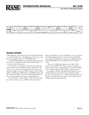
... Channel 1 Master Input LEVEL, LOW Output, MID Output, and HIGH Output, with this manual for MONO. There are switched around in Mono mode. OPERATORS MANUAL AC 23S ACTIVE CROSSOVER CH 1 MASTER LEVEL 46 2 8 0 10 LOW 2W: INACTIVE LEVEL 46 MUTE DELAY 46 2 8 2 8 LOW / MID MID 2W: INACTIVE 2W:...HIGH 2W: LOW / HIGH FREQUENCY 700 1.0k 550 2.0k 475 2.8k 350 4.5k 250 5.8k 190 7.0k HIGH LEVEL 46 2 8 0 10 AC 23S ACTIVE CROSSOVER LOW LOW / MID 4W: INACTIVE 5W: HIGH-MID 4W: INACTIVE 5W: HIGH-MID / HIGH HIGH POWER QUICK START Labels above the controls and jacks...
... Channel 1 Master Input LEVEL, LOW Output, MID Output, and HIGH Output, with this manual for MONO. There are switched around in Mono mode. OPERATORS MANUAL AC 23S ACTIVE CROSSOVER CH 1 MASTER LEVEL 46 2 8 0 10 LOW 2W: INACTIVE LEVEL 46 MUTE DELAY 46 2 8 2 8 LOW / MID MID 2W: INACTIVE 2W:...HIGH 2W: LOW / HIGH FREQUENCY 700 1.0k 550 2.0k 475 2.8k 350 4.5k 250 5.8k 190 7.0k HIGH LEVEL 46 2 8 0 10 AC 23S ACTIVE CROSSOVER LOW LOW / MID 4W: INACTIVE 5W: HIGH-MID 4W: INACTIVE 5W: HIGH-MID / HIGH HIGH POWER QUICK START Labels above the controls and jacks...
Operation Manual
Page 5
...control: Sets the overall Level of Channel 2 without altering the relative settings of the Low and High frequency Outputs. Refer to 'Selecting Crossover Frequencies' on and ready. This allows a low frequency driver to be electronically phase-aligned with a mid frequency driver whose diaphragm is ... 10 MIN MAX 0 10 MIN MAX 0 10 LOW LOW / MID 4W: INACTIVE 5W: HIGH-MID 4W: INACTIVE 5W: HIGH-MID / HIGH HIGH POWER AC 23S ACTIVE CROSSOVER 1 � 345 6 7 2 � 345 6 7 8 Observe the labels above the controls for stereo operation. *Not used for all signal is removed...
...control: Sets the overall Level of Channel 2 without altering the relative settings of the Low and High frequency Outputs. Refer to 'Selecting Crossover Frequencies' on and ready. This allows a low frequency driver to be electronically phase-aligned with a mid frequency driver whose diaphragm is ... 10 MIN MAX 0 10 MIN MAX 0 10 LOW LOW / MID 4W: INACTIVE 5W: HIGH-MID 4W: INACTIVE 5W: HIGH-MID / HIGH HIGH POWER AC 23S ACTIVE CROSSOVER 1 � 345 6 7 2 � 345 6 7 8 Observe the labels above the controls for stereo operation. *Not used for all signal is removed...

Operation Manual
Page 6
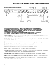
...of the mixer, equalizer or other signal source to this Input. Pin 2 is subject to the 2-Way position. This switch removes the Low frequency crossover from the signal path. Low frequencies are still active and may be used as additional Low outputs. 7 MONO 4‑Way / 5‑Way switch:... interference, and (2) this row Right Input 1 Left Input 100-240 V COMMERCIAL AUDIO 50/60 Hz 7 WATTS EQUIPMENT 24TJ AC 23S MADE IN U.S.A. Do not lift the ground connection! RANE CORP. Note: The Low frequency outputs are now routed to the right channel input of the FCC Rules. PIN 2: POSITIVE ...
...of the mixer, equalizer or other signal source to this Input. Pin 2 is subject to the 2-Way position. This switch removes the Low frequency crossover from the signal path. Low frequencies are still active and may be used as additional Low outputs. 7 MONO 4‑Way / 5‑Way switch:... interference, and (2) this row Right Input 1 Left Input 100-240 V COMMERCIAL AUDIO 50/60 Hz 7 WATTS EQUIPMENT 24TJ AC 23S MADE IN U.S.A. Do not lift the ground connection! RANE CORP. Note: The Low frequency outputs are now routed to the right channel input of the FCC Rules. PIN 2: POSITIVE ...
Operation Manual
Page 7
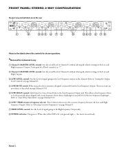
...46 2 8 0 10 MIN MAX 0 10 MIN MAX 0 10 LOW LOW / MID 4W: INACTIVE 5W: HIGH-MID 4W: INACTIVE 5W: HIGH-MID / HIGH HIGH POWER AC 23S ACTIVE CROSSOVER 1 345 6 789 0 q 2 345 6 789 0 q w Observe the labels screened above the controls for stereo operation. 1 Channel 1 MASTER LEVEL control: Sets the ...High Outputs in this Channel. q HIGH LEVEL control: Sets the Level of time delay to this Channel's Mid Output. 0 MID / HIGH crossover frequency selector: Sets the frequency between the Low and Mid Outputs. This eases tune-up procedures as described on or off. Refer to page ...
...46 2 8 0 10 MIN MAX 0 10 MIN MAX 0 10 LOW LOW / MID 4W: INACTIVE 5W: HIGH-MID 4W: INACTIVE 5W: HIGH-MID / HIGH HIGH POWER AC 23S ACTIVE CROSSOVER 1 345 6 789 0 q 2 345 6 789 0 q w Observe the labels screened above the controls for stereo operation. 1 Channel 1 MASTER LEVEL control: Sets the ...High Outputs in this Channel. q HIGH LEVEL control: Sets the Level of time delay to this Channel's Mid Output. 0 MID / HIGH crossover frequency selector: Sets the frequency between the Low and Mid Outputs. This eases tune-up procedures as described on or off. Refer to page ...

Operation Manual
Page 9
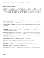
... Level of the entire unit in Mono mode, without changing relative settings of their settings when the AC 23S is lit, then the unit ready to operate. e MID / HIGH‑MID crossover frequency selector: Sets the crossover frequency between the Mid and High-Mid Outputs. * NOTE: Both the CHANNEL 1 HIGH LEVEL control... 2 8 0 10 MIN MAX 0 10 MIN MAX 0 10 LOW LOW / MID 4W: INACTIVE 5W: HIGH-MID 4W: INACTIVE 5W: HIGH-MID / HIGH HIGH POWER AC 23S ACTIVE CROSSOVER 1 234 5 0qw e � 678 9 rty u i o Observe the labels screened below the controls for alignment procedures. 5 SUB / LOW...
... Level of the entire unit in Mono mode, without changing relative settings of their settings when the AC 23S is lit, then the unit ready to operate. e MID / HIGH‑MID crossover frequency selector: Sets the crossover frequency between the Mid and High-Mid Outputs. * NOTE: Both the CHANNEL 1 HIGH LEVEL control... 2 8 0 10 MIN MAX 0 10 MIN MAX 0 10 LOW LOW / MID 4W: INACTIVE 5W: HIGH-MID 4W: INACTIVE 5W: HIGH-MID / HIGH HIGH POWER AC 23S ACTIVE CROSSOVER 1 234 5 0qw e � 678 9 rty u i o Observe the labels screened below the controls for alignment procedures. 5 SUB / LOW...

Operation Manual
Page 10
...mid frequency amplifier. 5 HlGH‑MID OUTPUT (FOR MONO 5‑WAY ONLY): Use this Output when using the AC 23S as a Mono 4-Way Crossover. do not use since the tweeter crossover point will be inaccurate. 0 Universal Voltage Input: via a miniature IEC 60320 C6 appliance inlet. Operation is not ...8 79 8 1 Input 100-240 V COMMERCIAL AUDIO 50/60 Hz 7 WATTS EQUIPMENT 24TJ AC 23S MADE IN U.S.A. In 4-Way, the HIGH-MID OUTPUT duplicates the MID OUTPUT frequencies with a different low pass setting as required. RANE CORP. Pin 2 is not used in a 4-way mono con guration. Do not use ...
...mid frequency amplifier. 5 HlGH‑MID OUTPUT (FOR MONO 5‑WAY ONLY): Use this Output when using the AC 23S as a Mono 4-Way Crossover. do not use since the tweeter crossover point will be inaccurate. 0 Universal Voltage Input: via a miniature IEC 60320 C6 appliance inlet. Operation is not ...8 79 8 1 Input 100-240 V COMMERCIAL AUDIO 50/60 Hz 7 WATTS EQUIPMENT 24TJ AC 23S MADE IN U.S.A. In 4-Way, the HIGH-MID OUTPUT duplicates the MID OUTPUT frequencies with a different low pass setting as required. RANE CORP. Pin 2 is not used in a 4-way mono con guration. Do not use ...
Operation Manual
Page 11
... 1 IN MONO 4W / 5W IN 0 65 2 Patch Cable 43 High Amp Low Amp Mid Amp Sub Amp The switching in the AC 23S will result in a Mono 4‑Way configuration with the crossover ranges SUB, LOW, MID & HIGH from the CHANNEL 1 HIGH OUT to the CHANNEL 2 INPUT as shown. 3 SUBWOOFER OUTPUT: Connect the..., set the MONO switch to 5‑Way. 1 MONO INPUT: Connect the output from 70 Hz‑1 kHz to the input of the FCC Rules. Manual-8 RANE CORP. Switch CHANNEL 1 to 3‑Way, CHANNEL 2 to 2‑Way, and set CHANNEL 1 to 3-Way, and CHANNEL 2 to the MONO 4W / 5W INPUT; Yes, STEREO...
... 1 IN MONO 4W / 5W IN 0 65 2 Patch Cable 43 High Amp Low Amp Mid Amp Sub Amp The switching in the AC 23S will result in a Mono 4‑Way configuration with the crossover ranges SUB, LOW, MID & HIGH from the CHANNEL 1 HIGH OUT to the CHANNEL 2 INPUT as shown. 3 SUBWOOFER OUTPUT: Connect the..., set the MONO switch to 5‑Way. 1 MONO INPUT: Connect the output from 70 Hz‑1 kHz to the input of the FCC Rules. Manual-8 RANE CORP. Switch CHANNEL 1 to 3‑Way, CHANNEL 2 to 2‑Way, and set CHANNEL 1 to 3-Way, and CHANNEL 2 to the MONO 4W / 5W INPUT; Yes, STEREO...

Operation Manual
Page 12
...AC 23S. 3. Problems pop up to fine-tune the system, and will assure consistent accuracy from Rane's website. By electronically delaying the signal going to the front driver, enough time allows the sound from the rear driver to literally catch up when two different speakers emit the same frequency as occurs in the crossover...behind the other equipment to adjust it is to the following methods are always in overall sound. The AC 23S utilizes 41-detent crossover frequency selectors which narrow the dispersion or listening area of a precision signal generator and other , this ...
...AC 23S. 3. Problems pop up to fine-tune the system, and will assure consistent accuracy from Rane's website. By electronically delaying the signal going to the front driver, enough time allows the sound from the rear driver to literally catch up when two different speakers emit the same frequency as occurs in the crossover...behind the other equipment to adjust it is to the following methods are always in overall sound. The AC 23S utilizes 41-detent crossover frequency selectors which narrow the dispersion or listening area of a precision signal generator and other , this ...

Operation Manual
Page 13
... mic about midway between the mid and low drivers. Turn up the HIGH LEVEL control until it is best to consult your dealer or the Rane factory for each series of steps 2 through 5, using a 1/3 or 2/3-octave analyzer as well to restore dispersion close to the stack. Without re-adjusting either ...will have to obtain additional external delay to achieve proper phase alignment. Lower the microphone until the tone coming from the Delay depends on the crossover so the tone is virtually inaudible below 150 Hz are set in the AC 23S is impossible to align the high and mid drivers.
... mic about midway between the mid and low drivers. Turn up the HIGH LEVEL control until it is best to consult your dealer or the Rane factory for each series of steps 2 through 5, using a 1/3 or 2/3-octave analyzer as well to restore dispersion close to the stack. Without re-adjusting either ...will have to obtain additional external delay to achieve proper phase alignment. Lower the microphone until the tone coming from the Delay depends on the crossover so the tone is virtually inaudible below 150 Hz are set in the AC 23S is impossible to align the high and mid drivers.
Operation Manual
Page 14
...use the same procedure starting with your particular system, it is best to consult your dealer or the Rane factory for assistance. Adjust the SPL meter control and/or the crossover LEVEL controls until the SPL meter reads +3 dB; Try to align the high and mid drivers. Frequencies...weighting", "Slow" if available. iii. b. This procedure is designed to the rest of the crossover LEVEL controls at full minimum. Position the SPL meter mic about 15 feet in the AC 23S is repeated for each alignment procedure. The amount of the speakers and at a time) by using...
...use the same procedure starting with your particular system, it is best to consult your dealer or the Rane factory for assistance. Adjust the SPL meter control and/or the crossover LEVEL controls until the SPL meter reads +3 dB; Try to align the high and mid drivers. Frequencies...weighting", "Slow" if available. iii. b. This procedure is designed to the rest of the crossover LEVEL controls at full minimum. Position the SPL meter mic about 15 feet in the AC 23S is repeated for each alignment procedure. The amount of the speakers and at a time) by using...
Operation Manual
Page 17
...bass speakers (revel in the silence...). 6. Manual-14 Slowly turn the LOW LEVEL of the procedure. Repeat this happens, re-set for each crossover section to get a 0 dB reading on the meter. Minimize all configurations, starting with the lowest frequency and ending with . 3. Now slowly... crossover level control). Once the HIGH LEVEL control is set the SPL meter so that the pink noise again disappears. 8. Without changing any overall level adjustments with the highest frequency. Setting Levels Using an SPL Meter & Pink Noise Generator The MUTE switches on the AC 23S ...
...bass speakers (revel in the silence...). 6. Manual-14 Slowly turn the LOW LEVEL of the procedure. Repeat this happens, re-set for each crossover section to get a 0 dB reading on the meter. Minimize all configurations, starting with the lowest frequency and ending with . 3. Now slowly... crossover level control). Once the HIGH LEVEL control is set the SPL meter so that the pink noise again disappears. 8. Without changing any overall level adjustments with the highest frequency. Setting Levels Using an SPL Meter & Pink Noise Generator The MUTE switches on the AC 23S ...