
Owners Manual
Page 1
63-1110.fm Page 1 Friday, September 22, 2000 3:33 PM Mail Guard Owner's Manual Please read before using this equipment.
63-1110.fm Page 1 Friday, September 22, 2000 3:33 PM Mail Guard Owner's Manual Please read before using this equipment.
Owners Manual
Page 2
63-1110.fm Page 2 Friday, September 22, 2000 3:33 PM ˆ Important Information WARNING: To reduce the risk of the FCC Rules. NO USER-SERVICEABLE PARTS INSIDE. This symbol is intended to inform you to constitute a risk of electric shock. Operation is intended to alert... you that might be of sufficient magnitude to the presence of uninsulated dangerous voltage within the product's enclosure that important operating and maintenance instructions are trademarks used by RadioShack Corporation. 2 Important Information REFER SERVICING ...
63-1110.fm Page 2 Friday, September 22, 2000 3:33 PM ˆ Important Information WARNING: To reduce the risk of the FCC Rules. NO USER-SERVICEABLE PARTS INSIDE. This symbol is intended to inform you to constitute a risk of electric shock. Operation is intended to alert... you that might be of sufficient magnitude to the presence of uninsulated dangerous voltage within the product's enclosure that important operating and maintenance instructions are trademarks used by RadioShack Corporation. 2 Important Information REFER SERVICING ...
Owners Manual
Page 3
... of FCC Rules. Product: Mail Guard Model: 63-1110 Responsible Party: RadioShack 100 Throckmorton Fort Worth, TX 76102 Phone: 817-415-3200 THE FCC WANTS YOU TO KNOW This equipment complies with the limits for a Class B digital device as specified in a residential area. These limits provide reasonable protection against radio and TV interference in Part 15 of the following...
... of FCC Rules. Product: Mail Guard Model: 63-1110 Responsible Party: RadioShack 100 Throckmorton Fort Worth, TX 76102 Phone: 817-415-3200 THE FCC WANTS YOU TO KNOW This equipment complies with the limits for a Class B digital device as specified in a residential area. These limits provide reasonable protection against radio and TV interference in Part 15 of the following...
Owners Manual
Page 4
... Mail Guard is opened), the system's base (receiver) beeps and its indicator lights. If you cannot eliminate the interference, the FCC requires that you can set the transmitter to operate the equipment. ˆ Introduction Using your local RadioShack store if the problem still exists. Changes or modifications not expressly approved by RadioShack may cause interference and void the user's authority to the desired sensitivity setting...
... Mail Guard is opened), the system's base (receiver) beeps and its indicator lights. If you cannot eliminate the interference, the FCC requires that you can set the transmitter to operate the equipment. ˆ Introduction Using your local RadioShack store if the problem still exists. Changes or modifications not expressly approved by RadioShack may cause interference and void the user's authority to the desired sensitivity setting...
Owners Manual
Page 5
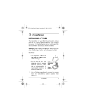
... mix old and new batteries, different types of batteries (standard, alkaline, or rechargeable), or rechargeable batteries of different capacities. Use a Phillips screwdriver to remove the screws from children. Swallowing a button-cell battery can be fatal. 63-1110.fm Page 5 Friday, September 22, 2000 3:33 PM ˆ Installation INSTALLING BATTERIES The transmitter for your Mail Guard system comes with two 3V CR2032 lithium batteries (not installed) for power. Battery Retaining Clip Photo Sensor 1. Warning: Keep...
... mix old and new batteries, different types of batteries (standard, alkaline, or rechargeable), or rechargeable batteries of different capacities. Use a Phillips screwdriver to remove the screws from children. Swallowing a button-cell battery can be fatal. 63-1110.fm Page 5 Friday, September 22, 2000 3:33 PM ˆ Installation INSTALLING BATTERIES The transmitter for your Mail Guard system comes with two 3V CR2032 lithium batteries (not installed) for power. Battery Retaining Clip Photo Sensor 1. Warning: Keep...
Owners Manual
Page 6
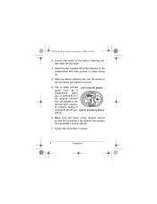
... channel and set Low/Hi to the desired light sensitivity. (Factory setting is channel B with their positive (+) sides facing up. 4. Loosen the screw on the battery retaining clip, then slide the clip aside. 3. Make sure the black o-ring remains secure around the transmitter's top cabinet, then replace the transmitter's bottom cabinet. 7. 63-1110.fm Page 6 Friday, September 22, 2000 3:33 PM 2. Install the two...
... channel and set Low/Hi to the desired light sensitivity. (Factory setting is channel B with their positive (+) sides facing up. 4. Loosen the screw on the battery retaining clip, then slide the clip aside. 3. Make sure the black o-ring remains secure around the transmitter's top cabinet, then replace the transmitter's bottom cabinet. 7. 63-1110.fm Page 6 Friday, September 22, 2000 3:33 PM 2. Install the two...
Owners Manual
Page 7
... 5 to release the transmitter. You might damage the transmitter, its bracket without releasing it from the lever. TESTING THE SYSTEM Before you install your system and permanently mount any components, test the transmitter and base (receiver) to determine the best location and set up. 63-1110.fm Page 7 Friday, September 22, 2000 3:33 PM Replacing Batteries When the transmitter stops operating properly, replace the batteries. 1. Warning: Dispose of old batteries promptly and properly.
... 5 to release the transmitter. You might damage the transmitter, its bracket without releasing it from the lever. TESTING THE SYSTEM Before you install your system and permanently mount any components, test the transmitter and base (receiver) to determine the best location and set up. 63-1110.fm Page 7 Friday, September 22, 2000 3:33 PM Replacing Batteries When the transmitter stops operating properly, replace the batteries. 1. Warning: Dispose of old batteries promptly and properly.
Owners Manual
Page 8
... transmitter inside the mailbox. (Use masking tape to monitor the base (receiver) as you test the transmitter's range and location from outside. 1. Close the mailbox door, then open it again. 3. Press RESET on Page 5) and repeat Steps 1-3. If the current channel does not transmit properly, change the channel setting (see Step 5 "Installing Batteries" on the base (receiver). 3. Open the closet door, allowing light to make sure the base beeps...
... transmitter inside the mailbox. (Use masking tape to monitor the base (receiver) as you test the transmitter's range and location from outside. 1. Close the mailbox door, then open it again. 3. Press RESET on Page 5) and repeat Steps 1-3. If the current channel does not transmit properly, change the channel setting (see Step 5 "Installing Batteries" on the base (receiver). 3. Open the closet door, allowing light to make sure the base beeps...
Owners Manual
Page 9
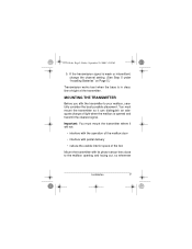
... whenever Installation 9 If the transmission signal is weak or intermittent, change of light when the mailbox is in clear, line-of-sight of the box Mount the transmitter with its photo-sensor lens close to your mailbox, carefully consider the best possible placement. Important: You must mount the transmitter so it will not: • interfere with the operation of the mailbox door...
... whenever Installation 9 If the transmission signal is weak or intermittent, change of light when the mailbox is in clear, line-of-sight of the box Mount the transmitter with its photo-sensor lens close to your mailbox, carefully consider the best possible placement. Important: You must mount the transmitter so it will not: • interfere with the operation of the mailbox door...
Owners Manual
Page 10
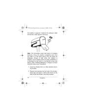
... door (or other desired mounting surface). 2. Remove the backing from one side of the doublesided tape and place it (sticky side down) on Page 5) to the base. Close the mailbox completely each time you open it so the photo sensor lens can sense an adequate change of light and sends a radio signal to lower the photo-sensor lens' sensitivity. 1. 63-1110...
... door (or other desired mounting surface). 2. Remove the backing from one side of the doublesided tape and place it (sticky side down) on Page 5) to the base. Close the mailbox completely each time you open it so the photo sensor lens can sense an adequate change of light and sends a radio signal to lower the photo-sensor lens' sensitivity. 1. 63-1110...
Owners Manual
Page 11
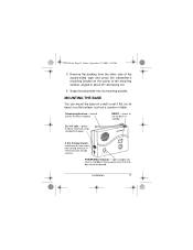
... sources. Telescoping Antenna - RESET - press to set it flat (on its mounting bracket. A B C Channel Switch select one of the mounting surface, angled to about 45° and facing out. 4. 63-1110.fm Page 11 Friday, September 22, 2000 3:33 PM 3. power the base (receiver) using standard AC power. POWER/MAIL Indicator - DC 12V Jack - lights steadily red when in standby or flashes green when the mailbox...
... sources. Telescoping Antenna - RESET - press to set it flat (on its mounting bracket. A B C Channel Switch select one of the mounting surface, angled to about 45° and facing out. 4. 63-1110.fm Page 11 Friday, September 22, 2000 3:33 PM 3. power the base (receiver) using standard AC power. POWER/MAIL Indicator - DC 12V Jack - lights steadily red when in standby or flashes green when the mailbox...
Owners Manual
Page 12
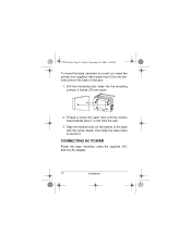
...from the wall. 3. Thread a screw into the mounting surface, 3 inches (76 mm) apart. 2. CONNECTING AC POWER Power the base (receiver) using the supplied 12V, 200 mA AC adapter. 12 Installation 63-1110.fm Page 12 Friday, September 22, 2000 3:33 PM To mount the base (receiver) on the back of the base with heads that... fit into the keyhole slots on a wall, you need two screws (not supplied) with the screw heads, then slide the base down to secure ...
...from the wall. 3. Thread a screw into the mounting surface, 3 inches (76 mm) apart. 2. CONNECTING AC POWER Power the base (receiver) using the supplied 12V, 200 mA AC adapter. 12 Installation 63-1110.fm Page 12 Friday, September 22, 2000 3:33 PM To mount the base (receiver) on the back of the base with heads that... fit into the keyhole slots on a wall, you need two screws (not supplied) with the screw heads, then slide the base down to secure ...
Owners Manual
Page 13
...Follow these specifications could damage the base or the adapter. • Always connect the AC adapter to the base before you connect it from the base. Installation 13 63-1110.fm Page 13 Friday, September 22, 2000 3:33 PM Cautions: You must fit the base's DC 12V jack. Using an ...be set to AC power. 1. Plug the other end of the adapter into the base's DC 12V jack. 2. The supplied adapter meets these specifi- The red POWER indicator on the base lights. that does not meet these steps to connect the base to positive and its plug must use a Class 2 power ...
...Follow these specifications could damage the base or the adapter. • Always connect the AC adapter to the base before you connect it from the base. Installation 13 63-1110.fm Page 13 Friday, September 22, 2000 3:33 PM Cautions: You must fit the base's DC 12V jack. Using an ...be set to AC power. 1. Plug the other end of the adapter into the base's DC 12V jack. 2. The supplied adapter meets these specifi- The red POWER indicator on the base lights. that does not meet these steps to connect the base to positive and its plug must use a Class 2 power ...
Owners Manual
Page 14
... the Mail Guard system's internal components can cause a malfunction and 14 Operation Slide A B C on Page 12, then close the mailbox door. 2. The red POWER indicator on the base (receiver) for about 10 seconds and the green MAIL indicator flashes. When the mailbox is opened, the base beeps for the best reception. 4. Use and store the system only in "Mounting the Transmitter" on Page 9 and "Connecting AC Power" on...
... the Mail Guard system's internal components can cause a malfunction and 14 Operation Slide A B C on Page 12, then close the mailbox door. 2. The red POWER indicator on the base (receiver) for about 10 seconds and the green MAIL indicator flashes. When the mailbox is opened, the base beeps for the best reception. 4. Use and store the system only in "Mounting the Transmitter" on Page 9 and "Connecting AC Power" on...
Owners Manual
Page 15
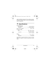
If your system is not performing as it should, take it to your local RadioShack store for assistance. ˆ Specifications Power Requirements Base (Receiver DC 12V, 200 mA Transmitter 2 × CR2032 Batteries Battery Life (at standby about 1 Year Dimensions (HWD) Base 39/16 × 45/16 × 13/8 in (90 × 109 × 35 mm) Transmitter 213/16 ×...
If your system is not performing as it should, take it to your local RadioShack store for assistance. ˆ Specifications Power Requirements Base (Receiver DC 12V, 200 mA Transmitter 2 × CR2032 Batteries Battery Life (at standby about 1 Year Dimensions (HWD) Base 39/16 × 45/16 × 13/8 in (90 × 109 × 35 mm) Transmitter 213/16 ×...

Owners Manual
Page 16
... in China All replaced parts and products, and products on how long an implied warranty lasts or the exclusion or limitation of excess voltage or current; (b) any RadioShack store. or (f) costs of the original warranty period. Ra- Repaired or replaced parts and products are warranted for the remainder of product removal, installation, set-up service adjustment or reinstallation. 63-1110.fm Page...
... in China All replaced parts and products, and products on how long an implied warranty lasts or the exclusion or limitation of excess voltage or current; (b) any RadioShack store. or (f) costs of the original warranty period. Ra- Repaired or replaced parts and products are warranted for the remainder of product removal, installation, set-up service adjustment or reinstallation. 63-1110.fm Page...


