Owners Manual
Page 2
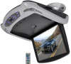
... Function Advanced Function USB/SD card Function Installation Connection Diagram Disc Information Cautions of Use Trouble Shooting Specifications 1 2 3 4 4 6 6 7-8 8 9 10-11 12 12 13 13 14 15 16 17 Specifications -13.3"Screen Panel -Two pieces of extra interchangeable housing -DVD -Super slim design,perfect combination of crystal glass panel and roof mount style -High...
... Function Advanced Function USB/SD card Function Installation Connection Diagram Disc Information Cautions of Use Trouble Shooting Specifications 1 2 3 4 4 6 6 7-8 8 9 10-11 12 12 13 13 14 15 16 17 Specifications -13.3"Screen Panel -Two pieces of extra interchangeable housing -DVD -Super slim design,perfect combination of crystal glass panel and roof mount style -High...
Owners Manual
Page 5
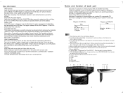
... gluey label- SD/USB/DVD/AV Switch key: Long press to your DVD player, Don't put discs in it for the unit Screen Savers 2. USB 13. patents and other limited viewing uses only unless otherwise authorized by the Macrovision Corportation. When press this copyright protection technology must be recorded. Each disc..., enabling you want . Short press to switch DVD/AV1/AV2 mode 10. DVD Loader 12. SD 14. AV2 Jack 15. Earphone Jack 1 2 3 4 5 6 7 8 9 10 11 12 13 14 15
... gluey label- SD/USB/DVD/AV Switch key: Long press to your DVD player, Don't put discs in it for the unit Screen Savers 2. USB 13. patents and other limited viewing uses only unless otherwise authorized by the Macrovision Corportation. When press this copyright protection technology must be recorded. Each disc..., enabling you want . Short press to switch DVD/AV1/AV2 mode 10. DVD Loader 12. SD 14. AV2 Jack 15. Earphone Jack 1 2 3 4 5 6 7 8 9 10 11 12 13 14 15
Owners Manual
Page 6
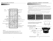
... chipset. And install special screws to avoid loose.) NOTICE: If you need to change different colors of input & output does not need to be connected. 13 Connection Diagram Video input (yellow) Left audio input (white) Right audio input (red) r=7 GND Battery +12V Video output (yellow) Left audio output (white) Right audio...
... chipset. And install special screws to avoid loose.) NOTICE: If you need to change different colors of input & output does not need to be connected. 13 Connection Diagram Video input (yellow) Left audio input (white) Right audio input (red) r=7 GND Battery +12V Video output (yellow) Left audio output (white) Right audio...

