Instruction Manual
Page 2
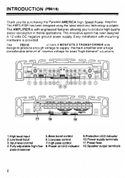
... 2 1.High level input 2.Low level input 3.1nput level control 4.Fully adjustable high/low pass crossover 5.Bass boost control 6.Low pass control 7.High pass control 8.Power on LED indicator 9.Protection LED indicator 10.Power supply terminals 11.Powerfuse 12.Speaker output terminals 2 The AMPLIFIER has been designed using the latest electronic technology avail able. INTRODUCT ION (PB618) Thank you to supply the main amplifier and a huge considerable a mount of reserve voltage for purchasing the Pyr amid AMERICA High Speed Power Amplifier...
... 2 1.High level input 2.Low level input 3.1nput level control 4.Fully adjustable high/low pass crossover 5.Bass boost control 6.Low pass control 7.High pass control 8.Power on LED indicator 9.Protection LED indicator 10.Power supply terminals 11.Powerfuse 12.Speaker output terminals 2 The AMPLIFIER has been designed using the latest electronic technology avail able. INTRODUCT ION (PB618) Thank you to supply the main amplifier and a huge considerable a mount of reserve voltage for purchasing the Pyr amid AMERICA High Speed Power Amplifier...
Instruction Manual
Page 3
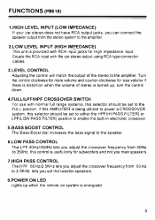
... PASS FILTER) or LPF(LOW PASS FILTER) position to the amplifier. Couple the RCA input with normal full range systems, this selector should be set the tweeter speakers. 8.POWER ON LED Lights up when the remote on system is turned up, turn the control down. 4.FULLILPF/HPF CROSSOVER SWITCH For use with the car stereo output using RCA type connector cables. 3.LEVEL CONTROL Adjusting the control will match the output of stereo is energized. 3 Turn the control clockwise for more volume and...
... PASS FILTER) or LPF(LOW PASS FILTER) position to the amplifier. Couple the RCA input with normal full range systems, this selector should be set the tweeter speakers. 8.POWER ON LED Lights up when the remote on system is turned up, turn the control down. 4.FULLILPF/HPF CROSSOVER SWITCH For use with the car stereo output using RCA type connector cables. 3.LEVEL CONTROL Adjusting the control will match the output of stereo is energized. 3 Turn the control clockwise for more volume and...

Instruction Manual
Page 4
... screw plate to cool down before restarting the amplifier. 10.POWER SUPPLY A. +12V To connect +12V DC power supply wire from the terminal of extreme high temperature conditions. C. The terminals are turned on the unit will light indicating that will disable the amplifier if it senses an input overload, speaker short circuit of battery. Bridge channels 3 & 4 into the following systems. A three channel Mo de. Brid ge Channels 3 & 4 into one high powered channel. Bridge channels 1 & 2 into a self preservation mode...
... screw plate to cool down before restarting the amplifier. 10.POWER SUPPLY A. +12V To connect +12V DC power supply wire from the terminal of extreme high temperature conditions. C. The terminals are turned on the unit will light indicating that will disable the amplifier if it senses an input overload, speaker short circuit of battery. Bridge channels 3 & 4 into the following systems. A three channel Mo de. Brid ge Channels 3 & 4 into one high powered channel. Bridge channels 1 & 2 into a self preservation mode...

Instruction Manual
Page 5
... RCA terminals for LOW LEVEL INPUT to the amplifier as indicated. (Fig. 1 B) WHEN YOU WANT TO BRIDGE THE AMPLIFIER PLEASE COMPLET THE FOLLOWING STEPS. 1. please wire as (Fig. 2B). If your STEREO only use a Y-adaptor connecting the stereo to match radios and equalizers with line level output.(Fig. 1A) If you STEREO has only RIGHT and LEFT o utputs then you must use RIGHT and LEFT outputs. ELECTRICAL & AUDIO CONNECTIONS (PB618) A. If your STEREO...
... RCA terminals for LOW LEVEL INPUT to the amplifier as indicated. (Fig. 1 B) WHEN YOU WANT TO BRIDGE THE AMPLIFIER PLEASE COMPLET THE FOLLOWING STEPS. 1. please wire as (Fig. 2B). If your STEREO only use a Y-adaptor connecting the stereo to match radios and equalizers with line level output.(Fig. 1A) If you STEREO has only RIGHT and LEFT o utputs then you must use RIGHT and LEFT outputs. ELECTRICAL & AUDIO CONNECTIONS (PB618) A. If your STEREO...

Instruction Manual
Page 6
ELECTRICAL & AUDIO CONNECTIONS (PB618) O O o 0 High Level Input Leads (To Radio Unit speaker Output) High Level Input Leads (To Radio Unit speaker Outout) (Fig. 1 B) � ''�o�;�Y-�,A�dap fT¢-Adap,:m o�t�t:�, (Fig.2A) 6
ELECTRICAL & AUDIO CONNECTIONS (PB618) O O o 0 High Level Input Leads (To Radio Unit speaker Output) High Level Input Leads (To Radio Unit speaker Outout) (Fig. 1 B) � ''�o�;�Y-�,A�dap fT¢-Adap,:m o�t�t:�, (Fig.2A) 6

Instruction Manual
Page 7
ELECTRICAL & AUDIO CONNECTIONS (PB618) ; SPEAKER CONNECTIONS You do not need to make any adjustment for the input connection of Amplifier before you connect the speaker output. 1. 4 Channel Output Mode Connect the speaker output terminals to the corresponding speaker. (Fig. 3A) (Fig.3A) 7 High Level Input Leads (To Radio Unit speaker Output) (Fig. 28) B. High Level Input Leads (To Radio Unit speaker Output) Car Stereo System (Four Channel Line Output) ;
ELECTRICAL & AUDIO CONNECTIONS (PB618) ; SPEAKER CONNECTIONS You do not need to make any adjustment for the input connection of Amplifier before you connect the speaker output. 1. 4 Channel Output Mode Connect the speaker output terminals to the corresponding speaker. (Fig. 3A) (Fig.3A) 7 High Level Input Leads (To Radio Unit speaker Output) (Fig. 28) B. High Level Input Leads (To Radio Unit speaker Output) Car Stereo System (Four Channel Line Output) ;

Instruction Manual
Page 8
The LEFT signal output from 2-RIGHT speaker terminal. use high quality speakers which are capable of handling the high power output. ELECTRICAL & AUDIO CONNECTIONS (PB618) 2. 2 Channel Output Mode You may want to bridge the Amplifier to the 3-4CH speaker terminal. (b)2-CHANNEL STEREO The RIGHT signal output from 1-LEFT speaker terminal. 8 In this mode only the 1-2CH and 3-4CH speaker will be activated. (Fig.3B) (Fig.3B) C.2-CHANNEL STEREO OUTPUT COMBINED WITH MONO SUBWOOFER OUTPUT MODE (a)SUBWOOFER Connect the speaker to a 2 CHANNEL output amplifier.
The LEFT signal output from 2-RIGHT speaker terminal. use high quality speakers which are capable of handling the high power output. ELECTRICAL & AUDIO CONNECTIONS (PB618) 2. 2 Channel Output Mode You may want to bridge the Amplifier to the 3-4CH speaker terminal. (b)2-CHANNEL STEREO The RIGHT signal output from 1-LEFT speaker terminal. 8 In this mode only the 1-2CH and 3-4CH speaker will be activated. (Fig.3B) (Fig.3B) C.2-CHANNEL STEREO OUTPUT COMBINED WITH MONO SUBWOOFER OUTPUT MODE (a)SUBWOOFER Connect the speaker to a 2 CHANNEL output amplifier.

Instruction Manual
Page 9
INTRODUCTION (PB718/PB918/PB2518/PB3818) ���J O �O 1.High level input 2.Low level input 3.Aux line output 4.lnput level control 5.Bass boost control 6.Low pass control 7.High pass control 8.Fully adjustable high/low pass crossover 9.Power on LED indicator 10.Protection LED indicator 11.Power supply terminals 12.Power fuse 13.Speaker output terminals 9
INTRODUCTION (PB718/PB918/PB2518/PB3818) ���J O �O 1.High level input 2.Low level input 3.Aux line output 4.lnput level control 5.Bass boost control 6.Low pass control 7.High pass control 8.Fully adjustable high/low pass crossover 9.Power on LED indicator 10.Protection LED indicator 11.Power supply terminals 12.Power fuse 13.Speaker output terminals 9
Instruction Manual
Page 10
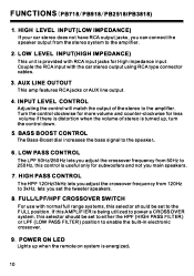
... adjust the crossover frequency from the stereo system to 3kHz, lets you main speakers. 7. FUNCTIONS (PB718/PB918/PB2518/PB3818) 1. AUX LINE OUTOUT This amp features RCA jacks or AUX line output. 4. LOW LEVEL INPUT(HIGH IMPEDANCE) This unit is energized, 10 FULL/LPF/HPF CROSSOVER SWITCH For use with normal full range systems, this AMPLIFIER is turned up when the remote on system is provided with the car stereo output using RCA type connector cables. 3. POWER ON LED Lights up , turn...
... adjust the crossover frequency from the stereo system to 3kHz, lets you main speakers. 7. FUNCTIONS (PB718/PB918/PB2518/PB3818) 1. AUX LINE OUTOUT This amp features RCA jacks or AUX line output. 4. LOW LEVEL INPUT(HIGH IMPEDANCE) This unit is energized, 10 FULL/LPF/HPF CROSSOVER SWITCH For use with normal full range systems, this AMPLIFIER is turned up when the remote on system is provided with the car stereo output using RCA type connector cables. 3. POWER ON LED Lights up , turn...

Instruction Manual
Page 11
... DC power supply wire from the chassis of extreme high temperature conditions. If the amplifier shutdown because of battery. Be sure to help ensure against speaker wire short circuits. 11 C. POWER FUSE The power fuse protects both this time please check your speaker wires that the amplifier has gone into a self preservation mode. FUNCTIONS (PB718/PB918/PB2518/PB3818) 10. GROUND To connect the ground wire from the terminal of an input overload or speaker short circuit please be reset...
... DC power supply wire from the chassis of extreme high temperature conditions. If the amplifier shutdown because of battery. Be sure to help ensure against speaker wire short circuits. 11 C. POWER FUSE The power fuse protects both this time please check your speaker wires that the amplifier has gone into a self preservation mode. FUNCTIONS (PB718/PB918/PB2518/PB3818) 10. GROUND To connect the ground wire from the terminal of an input overload or speaker short circuit please be reset...

Instruction Manual
Page 12
In th••palll STEREO MODE 9-.J '=-:JU 0 C c' =j C=� C= -- - ------ ---------- --- - ---- --------- 0 o tiir � = O lW1 0 = 0 .:m:m £00 .. = = X-OVER R FULL lPf HPF MONO MODE C 9jJrC =j I ' HPf l-B �l / \ Subwoofer 4·1.0111111 12 J [= suJ r[= a _ a 0 ""' Q .._.. , = = = "� X-OVER � FUll Lf'I G ill> ... +l1V FUU D 0 �!; 0 U oO �I1�DlJlo JO = o = 0 0 . ELECTRICAL&AUDIO CONNECTIONS ( PB718/PB918/PB2518/PB3818) Left Ri hi o;::C=n�';Jsur0 o � '-" " . .... .'CA � ...
In th••palll STEREO MODE 9-.J '=-:JU 0 C c' =j C=� C= -- - ------ ---------- --- - ---- --------- 0 o tiir � = O lW1 0 = 0 .:m:m £00 .. = = X-OVER R FULL lPf HPF MONO MODE C 9jJrC =j I ' HPf l-B �l / \ Subwoofer 4·1.0111111 12 J [= suJ r[= a _ a 0 ""' Q .._.. , = = = "� X-OVER � FUll Lf'I G ill> ... +l1V FUU D 0 �!; 0 U oO �I1�DlJlo JO = o = 0 0 . ELECTRICAL&AUDIO CONNECTIONS ( PB718/PB918/PB2518/PB3818) Left Ri hi o;::C=n�';Jsur0 o � '-" " . .... .'CA � ...

Instruction Manual
Page 13
... D.POWER CONNECTION 1. Battery Cha .. To make a good grounding and prevent motor boating noise problem con· nect another 12 gauge minimum wire from the (-) negative battery terminal to chassis of power supply directly to the battery (+)position terminal. 2. l. Connect the GND pole of stere o un it. 4. Connect the 'Remote' pole to the receiver power antenna lead. 8 I! �'W�'7fT\�S7 8 + N + + Vehicle'. This may be connected to external switch...
... D.POWER CONNECTION 1. Battery Cha .. To make a good grounding and prevent motor boating noise problem con· nect another 12 gauge minimum wire from the (-) negative battery terminal to chassis of power supply directly to the battery (+)position terminal. 2. l. Connect the GND pole of stere o un it. 4. Connect the 'Remote' pole to the receiver power antenna lead. 8 I! �'W�'7fT\�S7 8 + N + + Vehicle'. This may be connected to external switch...

Instruction Manual
Page 14
... that this is a high power unit which generates high electrical energy and heat Therefore be sure to install the unit in your car trunk or deck as it is protected from vibration. Check clearance all mounting hardware, While the Amplifier can be a driving hazard should you be sure to leave enough room for wiring. Secure the amplifier tightly. Do not leave...
... that this is a high power unit which generates high electrical energy and heat Therefore be sure to install the unit in your car trunk or deck as it is protected from vibration. Check clearance all mounting hardware, While the Amplifier can be a driving hazard should you be sure to leave enough room for wiring. Secure the amplifier tightly. Do not leave...
Instruction Manual
Page 15
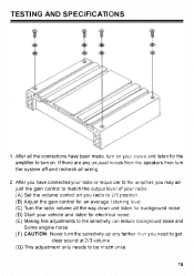
TESTING AND SPECIFICATIONS J 1. After you have been made, turn on . After all the way down If there are any unusual noises from the speakers then turn on your radio. (A) Set the volume control on you radio to 2/3 position (8) Adjust the gain control for an average listening level. (e) Turn the radio volume all the connections have connected your radio or requallzer to the amplifier, you may ad just the gain control to match the output level of your stereo and listen for the amplifier to turn the system off and recheck all wiring. 2.
TESTING AND SPECIFICATIONS J 1. After you have been made, turn on . After all the way down If there are any unusual noises from the speakers then turn on your radio. (A) Set the volume control on you radio to 2/3 position (8) Adjust the gain control for an average listening level. (e) Turn the radio volume all the connections have connected your radio or requallzer to the amplifier, you may ad just the gain control to match the output level of your stereo and listen for the amplifier to turn the system off and recheck all wiring. 2.

Instruction Manual
Page 16
... 2.496kg PB918 2. 654kg PB2518 3.264kg PB3818 3.962kg 16 Output P o w e r @ 14.4VDC 1 K HZ RMS power @4ohms RMS power @ 2 ohms RMS power @ 1 ohms MAX power Output PB618: PB718: PB918: Pb2518: Pb3818: 50Wx4 35Wx2 50Wx2 75Wx2 100Wx2 100Wx4 70Wx2 100Wx2 150Wx2 200Wx2 2000W 1000W 2000W 3000W 5000W PB618 =200W X 2 or 2000Wx 2 and 200Wx 1 2 . Matching Speaker Impedance Stereo Mode: 2-4 Ohms Bridged Mode: 4-8 Ohms 8. Input Sensitivity 250mV ( Low Level) 2.5V (High Level) 6. MaX.imum Current Dr aw. .. ... ... .. ... BrI...
... 2.496kg PB918 2. 654kg PB2518 3.264kg PB3818 3.962kg 16 Output P o w e r @ 14.4VDC 1 K HZ RMS power @4ohms RMS power @ 2 ohms RMS power @ 1 ohms MAX power Output PB618: PB718: PB918: Pb2518: Pb3818: 50Wx4 35Wx2 50Wx2 75Wx2 100Wx2 100Wx4 70Wx2 100Wx2 150Wx2 200Wx2 2000W 1000W 2000W 3000W 5000W PB618 =200W X 2 or 2000Wx 2 and 200Wx 1 2 . Matching Speaker Impedance Stereo Mode: 2-4 Ohms Bridged Mode: 4-8 Ohms 8. Input Sensitivity 250mV ( Low Level) 2.5V (High Level) 6. MaX.imum Current Dr aw. .. ... ... .. ... BrI...

