
English Manual
Page 3
...Always secure the weight stack with the lock pin and lock after exercising to mount, dismount, and use only. Read all instructions in this product. 3 Do not use of the weight system (see LOCKING THE WEIGHT STACK on the pulleys. Place the weight system on the foot plate when performing an... exercise that could cause the weight system to protect the floor or carpet. If the cables bind as ...
...Always secure the weight stack with the lock pin and lock after exercising to mount, dismount, and use only. Read all instructions in this product. 3 Do not use of the weight system (see LOCKING THE WEIGHT STACK on the pulleys. Place the weight system on the foot plate when performing an... exercise that could cause the weight system to protect the floor or carpet. If the cables bind as ...
English Manual
Page 6
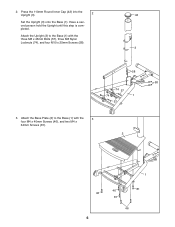
Attach the Upright (3) to the Base (1) with the three M8 x 45mm Bolts (57), three M8 Nylon Locknuts (74), and four M10 x 25mm Screws (58). 3 58 58 74 57 74 1 57 3. Have a second person hold the Upright until this step is completed. 2. Attach the Base Plate (2) to the Base (1) with the 3 four M4 x 40mm Screws (46), and two M4 x 64mm Screws (81). 2 46 6 1 46 81 81 46 Press the 110mm Round Inner Cap (42) into the Upright (3). 2 42 Set the Upright (3) onto the Base (1).
Attach the Upright (3) to the Base (1) with the three M8 x 45mm Bolts (57), three M8 Nylon Locknuts (74), and four M10 x 25mm Screws (58). 3 58 58 74 57 74 1 57 3. Have a second person hold the Upright until this step is completed. 2. Attach the Base Plate (2) to the Base (1) with the 3 four M4 x 40mm Screws (46), and two M4 x 64mm Screws (81). 2 46 6 1 46 81 81 46 Press the 110mm Round Inner Cap (42) into the Upright (3). 2 42 Set the Upright (3) onto the Base (1).

English Manual
Page 17
...each station may occur. The numbers show the correct route for the 12.5 lb. If the Cable has not been correctly routed, the weight system will not function properly and damage may vary due to make sure that the Cable has been assembled correctly. Note: The actual ...resistance at each arm. Use the diagram to differences in individual weight plates as well as friction between the cables, pulleys, and weight guides. weights. WEIGHT 1 2 3 4 5 6 7 8 9 10 11 12 RESISTANCE 14 23 32 41 50 59 68 77 86 95 102 110 ...
...each station may occur. The numbers show the correct route for the 12.5 lb. If the Cable has not been correctly routed, the weight system will not function properly and damage may vary due to make sure that the Cable has been assembled correctly. Note: The actual ...resistance at each arm. Use the diagram to differences in individual weight plates as well as friction between the cables, pulleys, and weight guides. weights. WEIGHT 1 2 3 4 5 6 7 8 9 10 11 12 RESISTANCE 14 23 32 41 50 59 68 77 86 95 102 110 ...
English Manual
Page 21
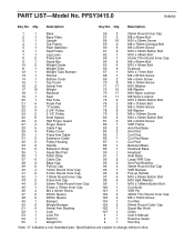
...-Model No. Description Key No. Description 1 1 Base 2 1 Base Plate 3 1 Upright 4 1 Top Frame 5 1 Rear Stabilizer 6 1 Seat Frame 7 1 Leg Lever 8 2 Press Arm 9 1 Squat Bar 10 2 Weight Guide 11 1 Weight Tube 12 1 Weight Tube Bumper 13 1 Shroud 14 1 Bottom Cover 15 1 Top Cover ... Inner Cap 46 4 M4 x 40mm Screw 47 2 25mm Spacer 48 2 38mm Spacer 49 1 Bumper 50 2 Weight Bumper 51 4 Swivel Arm Bushing 52 1 Lock 53 1 Lock Pin 54 1 Roll Pin 55 1 Weight Pin 56 2 57 3 58 16 59 2 60 6 61 2 62 1 63 1 64 2 65 4 ...
...-Model No. Description Key No. Description 1 1 Base 2 1 Base Plate 3 1 Upright 4 1 Top Frame 5 1 Rear Stabilizer 6 1 Seat Frame 7 1 Leg Lever 8 2 Press Arm 9 1 Squat Bar 10 2 Weight Guide 11 1 Weight Tube 12 1 Weight Tube Bumper 13 1 Shroud 14 1 Bottom Cover 15 1 Top Cover ... Inner Cap 46 4 M4 x 40mm Screw 47 2 25mm Spacer 48 2 38mm Spacer 49 1 Bumper 50 2 Weight Bumper 51 4 Swivel Arm Bushing 52 1 Lock 53 1 Lock Pin 54 1 Roll Pin 55 1 Weight Pin 56 2 57 3 58 16 59 2 60 6 61 2 62 1 63 1 64 2 65 4 ...
