
English Manual
Page 1
... TOLL-FREE: 1-888-533-1333 Mon.-Fri., 6 a.m.-6 p.m. Visit our website at www.proform.com new products, prizes, fitness tips, and much more! Save this equipment. Serial Number Decal (Under Seat) QUESTIONS? Write the serial number in this manual before using this manual for future reference. MST ON THE WEB: www.proformservice.com USER'S MANUAL CAUTION Read all precautions and instructions in the space above for...
... TOLL-FREE: 1-888-533-1333 Mon.-Fri., 6 a.m.-6 p.m. Visit our website at www.proform.com new products, prizes, fitness tips, and much more! Save this equipment. Serial Number Decal (Under Seat) QUESTIONS? Write the serial number in this manual before using this manual for future reference. MST ON THE WEB: www.proformservice.com USER'S MANUAL CAUTION Read all precautions and instructions in the space above for...
English Manual
Page 2
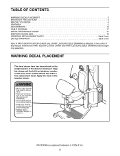
...-free telephone number on the weight system. Remove the PART IDENTIFICATION CHART and PART LIST/EXPLODED DRAWING before beginning assembly. PROFORM is a registered trademark of ICON IP, Inc. 2 WARNING DECAL PLACEMENT The decal shown here has been placed on the front cover of this manual. TABLE OF CONTENTS WARNING DECAL PLACEMENT 2 IMPORTANT PRECAUTIONS 3 BEFORE YOU BEGIN 4 ASSEMBLY 5 ADJUSTMENTS 14 CABLE DIAGRAM 17 WEIGHT RESISTANCE CHART 17 EXERCISE GUIDELINES 18 ORDERING REPLACEMENT PARTS Back Cover LIMITED WARRANTY...
...-free telephone number on the weight system. Remove the PART IDENTIFICATION CHART and PART LIST/EXPLODED DRAWING before beginning assembly. PROFORM is a registered trademark of ICON IP, Inc. 2 WARNING DECAL PLACEMENT The decal shown here has been placed on the front cover of this manual. TABLE OF CONTENTS WARNING DECAL PLACEMENT 2 IMPORTANT PRECAUTIONS 3 BEFORE YOU BEGIN 4 ASSEMBLY 5 ADJUSTMENTS 14 CABLE DIAGRAM 17 WEIGHT RESISTANCE CHART 17 EXERCISE GUIDELINES 18 ORDERING REPLACEMENT PARTS Back Cover LIMITED WARRANTY...
English Manual
Page 3
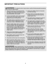
... dizziness at all users of 35 or persons with the top weight pinned in any commercial, rental, or institutional setting. 4. Replace all cables at all precautions. 3. Never release the ankle strap, leg lever, squat bar, leg press, curl bar, or handles while weights are adequately informed of this or any time while exercising, stop immediately and make sure that all times. Do not use the weight system. 5. Make...
... dizziness at all users of 35 or persons with the top weight pinned in any commercial, rental, or institutional setting. 4. Replace all cables at all precautions. 3. Never release the ankle strap, leg lever, squat bar, leg press, curl bar, or handles while weights are adequately informed of this or any time while exercising, stop immediately and make sure that all times. Do not use the weight system. 5. Make...
English Manual
Page 4
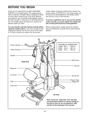
... PROFORM® FUSION 4.0 LX weight system. For your goal is PFSY3415.0. To help you to develop every major muscle group of weight stations designed to achieve the specific results you want. Pull-up Handle Pulley Housing Handle Right Side Backrest Curl Pad Seat Leg Lever ASSEMBLED DIMENSIONS: Height: 82 in. / 208 cm Width: 105 in. / 267 cm Depth: 94 in the manual...
... PROFORM® FUSION 4.0 LX weight system. For your goal is PFSY3415.0. To help you to develop every major muscle group of weight stations designed to achieve the specific results you want. Pull-up Handle Pulley Housing Handle Right Side Backrest Curl Pad Seat Leg Lever ASSEMBLED DIMENSIONS: Height: 82 in. / 208 cm Width: 105 in. / 267 cm Depth: 94 in the manual...
English Manual
Page 5
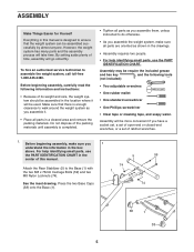
... you 1 understand the information in the box above. For help identifying small parts, use the PART IDENTIFICATION CHART in the center of its weight and size, the weight system should be assembled in the location where it . • Place all parts are oriented as you assemble it will be used. To hire an authorized service technician to assemble the weight system, call toll-free 1-800-445-2480...
... you 1 understand the information in the box above. For help identifying small parts, use the PART IDENTIFICATION CHART in the center of its weight and size, the weight system should be assembled in the location where it . • Place all parts are oriented as you assemble it will be used. To hire an authorized service technician to assemble the weight system, call toll-free 1-800-445-2480...
English Manual
Page 8
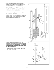
... on top. Engage the VKR Pin (101) into 6 the Upright (3) through the indicated holes. Orient the VKR Bumper (95) with an M4 x 16mm Screw (70). Attach the VKR Bumper to the Upright (3) with two M4 x 16mm Screws (70). Grease the M10 x 168mm Button Bolt (99). Attach the VKR Frame (82) to the Upright (3) with 7 the Bolt and an M10 Nylon Locknut (73...
... on top. Engage the VKR Pin (101) into 6 the Upright (3) through the indicated holes. Orient the VKR Bumper (95) with an M4 x 16mm Screw (70). Attach the VKR Bumper to the Upright (3) with two M4 x 16mm Screws (70). Grease the M10 x 168mm Button Bolt (99). Attach the VKR Frame (82) to the Upright (3) with 7 the Bolt and an M10 Nylon Locknut (73...

English Manual
Page 9
... tighten the Screws. Tighten the two M8 Nylon Locknuts (74) and the four M10 x 25mm Screws (58). 9. Repeat this step with two M10 x 80mm Button Bolts (97), two M10 Washers (71), two M10 Split Washers (98), and two M10 Nylon Locknuts (73). Repeat this step with four M10 x 25mm Screws (58). the Eyehook must rotate freely. Attach the Press Arm (8) without the wire...
... tighten the Screws. Tighten the two M8 Nylon Locknuts (74) and the four M10 x 25mm Screws (58). 9. Repeat this step with two M10 x 80mm Button Bolts (97), two M10 Washers (71), two M10 Split Washers (98), and two M10 Nylon Locknuts (73). Repeat this step with four M10 x 25mm Screws (58). the Eyehook must rotate freely. Attach the Press Arm (8) without the wire...

English Manual
Page 10
... Top Frame (4) with 12 an M10 x 64mm Button Bolt (75), two M10 Washers (71), two 5mm Spacers (25), and an M10 Nylon Locknut (73). Attach the Pulley and a Cable Trap (28) to the left Press Arm (8) with an M10 x 45mm Bolt (65) and an M10 Nylon Locknut (73). Attach a "V"-pulley (22) to hold the Press Arm Cable (30) in the groove of the...
... Top Frame (4) with 12 an M10 x 64mm Button Bolt (75), two M10 Washers (71), two 5mm Spacers (25), and an M10 Nylon Locknut (73). Attach the Pulley and a Cable Trap (28) to the left Press Arm (8) with an M10 x 45mm Bolt (65) and an M10 Nylon Locknut (73). Attach a "V"-pulley (22) to hold the Press Arm Cable (30) in the groove of the...

English Manual
Page 11
... Cable in the groove of the Weight Tube. Route the Press Arm Cable (30) through the Swivel Arm (16). Attach the Pulley and a Cable Trap (28) to hold the Cable in the groove of the Pulley. 11 73 62 30 26 28 26 24 28 65 24 30 73 4 18. Using the wire that is oriented to the Top Frame (4) with an M10 x 45mm Bolt...
... Cable in the groove of the Weight Tube. Route the Press Arm Cable (30) through the Swivel Arm (16). Attach the Pulley and a Cable Trap (28) to hold the Cable in the groove of the Pulley. 11 73 62 30 26 28 26 24 28 65 24 30 73 4 18. Using the wire that is oriented to the Top Frame (4) with an M10 x 45mm Bolt...

English Manual
Page 12
... 60 18 3 23. Attach a 2 3/4" Pulley (23) to the Upright (3) with an M10 x 53mm Button Bolt (61), two M10 Washers (71), two 5mm Spacers (25), two Finger Guards (27), and an M10 Nylon Locknut (73). 20. Orient the Finger Guards and Pulley as shown. See the inset drawing. Make sure the Press Arm Cable (30) is routed under the indicated welded...
... 60 18 3 23. Attach a 2 3/4" Pulley (23) to the Upright (3) with an M10 x 53mm Button Bolt (61), two M10 Washers (71), two 5mm Spacers (25), two Finger Guards (27), and an M10 Nylon Locknut (73). 20. Orient the Finger Guards and Pulley as shown. See the inset drawing. Make sure the Press Arm Cable (30) is routed under the indicated welded...

English Manual
Page 13
... the Bolt; Slide an Arm Pad Base (83) and an Arm Pad (84) 27 onto the VKR Frame (82). 24. Grease 6 67 73 7 70 49 26. Attach the Leg Lever (7) to 24 the Seat Frame (6) with the Bolt and an M10 Nylon Locknut (73). Slide two Foam Pads (21) onto the Seat Frame (6). Attach the Seat (19...Screw (68), and an M6 Washer (78). Repeat this step on the other side of the VKR Frame (82). 103 83 78 103 82 13 Hook the Seat Frame (6) onto the Upright (3) at the indicated location. 19 91 6 3 78 60 68 25. the Leg Lever must be able to an M10 x 71mm Bolt (67). Attach...
... the Bolt; Slide an Arm Pad Base (83) and an Arm Pad (84) 27 onto the VKR Frame (82). 24. Grease 6 67 73 7 70 49 26. Attach the Leg Lever (7) to 24 the Seat Frame (6) with the Bolt and an M10 Nylon Locknut (73). Slide two Foam Pads (21) onto the Seat Frame (6). Attach the Seat (19...Screw (68), and an M6 Washer (78). Repeat this step on the other side of the VKR Frame (82). 103 83 78 103 82 13 Hook the Seat Frame (6) onto the Upright (3) at the indicated location. 19 91 6 3 78 60 68 25. the Leg Lever must be able to an M10 x 71mm Bolt (67). Attach...

English Manual
Page 14
... benefit from the Upright (See ADJUSTING THE SEAT FRAME HEIGHT on the sides of the Press Arm Cable (30) with a Cable Clip (37). Note: To use solvents. See the inset drawing A. Replace any worn parts immediately. See the EXERCISE GUIDELINES on page 18 for important information about how to see the correct form for each time the weight system is used . Attach the other Pulley Housing in...
... benefit from the Upright (See ADJUSTING THE SEAT FRAME HEIGHT on the sides of the Press Arm Cable (30) with a Cable Clip (37). Note: To use solvents. See the inset drawing A. Replace any worn parts immediately. See the EXERCISE GUIDELINES on page 18 for important information about how to see the correct form for each time the weight system is used . Attach the other Pulley Housing in...
English Manual
Page 15
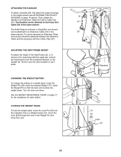
...). Insert the Weight Pin so that the bent end touches the weight stack. See the WEIGHT RESISTANCE CHART on the Upright (3). ATTACHING THE HANDLES To attach a Handle (33), first attach the pulley housings to remove it aside. Then, attach the Handle to an Extension Cable (31) in the same manner. CHANGING THE WEIGHT SETTING To change the setting of the Seat Frame (6), or to the weight system (see ATTACHING THE PULLEY HOUSING on...
...). Insert the Weight Pin so that the bent end touches the weight stack. See the WEIGHT RESISTANCE CHART on the Upright (3). ATTACHING THE HANDLES To attach a Handle (33), first attach the pulley housings to remove it aside. Then, attach the Handle to an Extension Cable (31) in the same manner. CHANGING THE WEIGHT SETTING To change the setting of the Seat Frame (6), or to the weight system (see ATTACHING THE PULLEY HOUSING on...

English Manual
Page 16
... Cables (31) to the Leg Lever (7) with another Cable Clip. Finally, attach the Curl Bar to the stored position. Move the Frame down to use the Frame to exercise, or up to the Leg Lever. ATTACHING THE CURL PAD To use the Curl Pad (87), first remove the 51mm Round Inner Cap (41) from the Frame and the Upright (3). Reengage the Pin into the Seat...
... Cables (31) to the Leg Lever (7) with another Cable Clip. Finally, attach the Curl Bar to the stored position. Move the Frame down to use the Frame to exercise, or up to the Leg Lever. ATTACHING THE CURL PAD To use the Curl Pad (87), first remove the 51mm Round Inner Cap (41) from the Frame and the Upright (3). Reengage the Pin into the Seat...

English Manual
Page 17
Use the diagram to differences in individual weight plates as well as friction between the cables, pulleys, and weight guides. weights. WEIGHT 1 2 3 4 5 6 7 8 9 10 11 12 RESISTANCE 14 23 32 41 50 59 68 77 86 95 102 110 17 Press Arm Cable (30) 7 6 4 3 9 8 5 2 1 WEIGHT RESISTANCE CHART The chart below shows the approximate weight resistance for the Cable. If the Cable has not been correctly routed, the weight system will not function properly and damage...
Use the diagram to differences in individual weight plates as well as friction between the cables, pulleys, and weight guides. weights. WEIGHT 1 2 3 4 5 6 7 8 9 10 11 12 RESISTANCE 14 23 32 41 50 59 68 77 86 95 102 110 17 Press Arm Cable (30) 7 6 4 3 9 8 5 2 1 WEIGHT RESISTANCE CHART The chart below shows the approximate weight resistance for the Cable. If the Cable has not been correctly routed, the weight system will not function properly and damage...
English Manual
Page 18
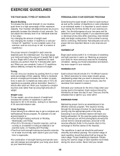
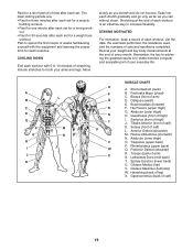
... using high amounts of weight that you , stick with 5 to 10 minutes of the body. Complete as many sets of 15 to 20 repetitions as running on a treadmill or riding an elliptical or an exercise cycle, on the next page to find the names of the muscles. WORKING OUT Each workout should last about half as long as the number...
... using high amounts of weight that you , stick with 5 to 10 minutes of the body. Complete as many sets of 15 to 20 repetitions as running on a treadmill or riding an elliptical or an exercise cycle, on the next page to find the names of the muscles. WORKING OUT Each workout should last about half as long as the number...
English Manual
Page 19
... set for a weight loss workout. out. • Rest for both your arms and legs. Move slowly as you stretch and do not bounce. List the date, the exercises performed, the resistance used, and the numbers of each exercise. Remember, the key to achieving the greatest results is an effective way to make exercise a regular and enjoyable part of your weight and key body measurements at the end of sets...
... set for a weight loss workout. out. • Rest for both your arms and legs. Move slowly as you stretch and do not bounce. List the date, the exercises performed, the resistance used, and the numbers of each exercise. Remember, the key to achieving the greatest results is an effective way to make exercise a regular and enjoyable part of your weight and key body measurements at the end of sets...
English Manual
Page 20
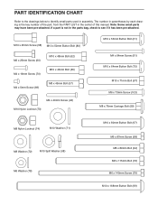
PART IDENTIFICATION CHART Refer to the drawings below to identify small parts used in the parts bag, check to see if it has been pre-attached. If a part is the key number of the part, from the PART LIST in the center of this manual. M10 x 25mm Screw (58) M10 x 50mm Button Bolt (80) M6 x 25mm Screw (60) M4 x 16mm Screw (70) M4 x 5mm Screw (69) M10 x 48mm Bolt (62) M10...
PART IDENTIFICATION CHART Refer to the drawings below to identify small parts used in the parts bag, check to see if it has been pre-attached. If a part is the key number of the part, from the PART LIST in the center of this manual. M10 x 25mm Screw (58) M10 x 50mm Button Bolt (80) M6 x 25mm Screw (60) M4 x 16mm Screw (70) M4 x 5mm Screw (69) M10 x 48mm Bolt (62) M10...
English Manual
Page 21
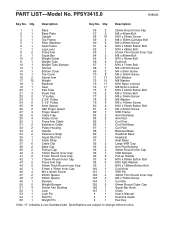
... Arm Pad Bushing 32mm Round Inner Cap VKR Bumper Pull-up Handle M10 x 80mm Button Bolt M10 Split Washer M10 x 168mm Button Bolt Curl Knob VKR Pin 32mm Thin Round Inner Cap M6 x 73mm Screw Curl Bar 64mm Round Outer Cap Squat Bar Hook Chain User's Manual Exercise Guide Hex Key Note: "#" indicates a non-illustrated part. Qty. Qty. PART LIST-Model No. Specifications are subject to change without notice. PFSY3415.0 R0805A Key...
... Arm Pad Bushing 32mm Round Inner Cap VKR Bumper Pull-up Handle M10 x 80mm Button Bolt M10 Split Washer M10 x 168mm Button Bolt Curl Knob VKR Pin 32mm Thin Round Inner Cap M6 x 73mm Screw Curl Bar 64mm Round Outer Cap Squat Bar Hook Chain User's Manual Exercise Guide Hex Key Note: "#" indicates a non-illustrated part. Qty. Qty. PART LIST-Model No. Specifications are subject to change without notice. PFSY3415.0 R0805A Key...
English Manual
Page 24
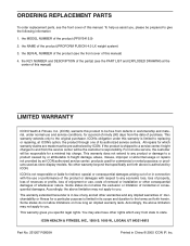
... replacing or repairing, at the center of this manual) LIMITED WARRANTY ICON Health & Fitness, Inc. (ICON), warrants this warranty is limited to any and all other warranty beyond that specifically set forth herein. Some states do not allow limitations on how long an implied warranty lasts. the KEY NUMBER and DESCRIPTION of the part(s) (see the front cover of merchantability or fitness for commercial or rental purposes; ICON's obligation under normal use and service...
... replacing or repairing, at the center of this manual) LIMITED WARRANTY ICON Health & Fitness, Inc. (ICON), warrants this warranty is limited to any and all other warranty beyond that specifically set forth herein. Some states do not allow limitations on how long an implied warranty lasts. the KEY NUMBER and DESCRIPTION of the part(s) (see the front cover of merchantability or fitness for commercial or rental purposes; ICON's obligation under normal use and service...

