

English Manual
Page 1
SEARS, ROEBUCK AND CO., HOFFMAN ESTATES, IL 60179 c 0 Serial Number Decal OWNER'S MANUAL 0 CAUTION!: Read all safety precautions and instructions in this manual before using this manual in a safe place for future reference. Keep this equipment. PRO•FORM® 65,...ARS Model No. 831.159213 Serial No. PATENT PENDING da? The serial number can be found in the space above. Write the serial number in the location shown below.
SEARS, ROEBUCK AND CO., HOFFMAN ESTATES, IL 60179 c 0 Serial Number Decal OWNER'S MANUAL 0 CAUTION!: Read all safety precautions and instructions in this manual before using this manual in a safe place for future reference. Keep this equipment. PRO•FORM® 65,...ARS Model No. 831.159213 Serial No. PATENT PENDING da? The serial number can be found in the space above. Write the serial number in the location shown below.

English Manual
Page 2
Use this equipment is especially important for persons over the age of 35 or persons with pre-existing health prob- Inspect and tighten all times. 5. Always wear athletic shoes for personal Injury 2 or property damage sustained by or through the use more than the designated handles. 4. To prevent damage to this equipment to tip. 6. Keep your physician. Always stand on the foot plate when performing any exercise that could cause this equipment, never use of this equipment. TABLE OF CONTENTS IMPORTANT SAFETY PRECAUTIONS BEFORE YOU BEGIN ASSEMBLY USING THE SYSTEM...
Use this equipment is especially important for persons over the age of 35 or persons with pre-existing health prob- Inspect and tighten all times. 5. Always wear athletic shoes for personal Injury 2 or property damage sustained by or through the use more than the designated handles. 4. To prevent damage to this equipment to tip. 6. Keep your physician. Always stand on the foot plate when performing any exercise that could cause this equipment, never use of this equipment. TABLE OF CONTENTS IMPORTANT SAFETY PRECAUTIONS BEFORE YOU BEGIN ASSEMBLY USING THE SYSTEM...

English Manual
Page 3
... at 1-800-9993756, Monday through Friday, 6 a.m. If you , please note the product model number and serial number before using the PROFORM SYSTEM 2. Mountain Time (excluding holidays). To help you to improve your cardiovascular fitness, shape and tone your safety and benefit, read this...please review the drawing below and familiarize yourself with the parts that are labeled. BEFORE YOU BEGIN Congratulations for selecting the versatile PROFORM® SYSTEM 2. Whether your goal is to achieve the specific results you enjoy an impressive variety of exercises in the convenience...
... at 1-800-9993756, Monday through Friday, 6 a.m. If you , please note the product model number and serial number before using the PROFORM SYSTEM 2. Mountain Time (excluding holidays). To help you to improve your cardiovascular fitness, shape and tone your safety and benefit, read this...please review the drawing below and familiarize yourself with the parts that are labeled. BEFORE YOU BEGIN Congratulations for selecting the versatile PROFORM® SYSTEM 2. Whether your goal is to achieve the specific results you enjoy an impressive variety of exercises in the convenience...

English Manual
Page 4
Insert the two 3/8" x 2 1/2" Carriage Bolts (60) up through the 112" Brass Bushings and the Press Arm. Attach the Foot Plate (25) to the Frame (11) with two 1/4" x 2 1/2" Bolts (5) and 1/4" Lou'r' v ht! Tap a 1/2" Hat Cap (39) onto one end of the Press Arm Axle. While holding a mallet against the first 1/2" Hat Cap (39), tap another 1/2" Hat Cap 4 onto the other end of the Press Arm Axle (43). The following tools are also needed. 1. Grease (included) and a small amount of soapy water are required for help identifying the small parts used . Slide the Frame (11) onto the ...
Insert the two 3/8" x 2 1/2" Carriage Bolts (60) up through the 112" Brass Bushings and the Press Arm. Attach the Foot Plate (25) to the Frame (11) with two 1/4" x 2 1/2" Bolts (5) and 1/4" Lou'r' v ht! Tap a 1/2" Hat Cap (39) onto one end of the Press Arm Axle. While holding a mallet against the first 1/2" Hat Cap (39), tap another 1/2" Hat Cap 4 onto the other end of the Press Arm Axle (43). The following tools are also needed. 1. Grease (included) and a small amount of soapy water are required for help identifying the small parts used . Slide the Frame (11) onto the ...
English Manual
Page 5
Tap a 1/2" Plastic Cap (63) onto the post. Slide the Pad onto the Left Butterfly Arm unto the Pad is the Arm with the lower end. I:1i11 52 61 . - - ` -N 62 11, . 62 n .. ' . ... - - 1 -•52 49 ,--• - 62 (, 1 5 63- 9 46 49 - Grease the post on the floor and insert a Pulley Sleeve (40) into each one. Wet the lower end of the Left Butterfly Arm and the inside of a Large Foam Pad (47) with two 3/8" x 3 1/2" Bolts (15), 3/8" Washers (61) 7 and 3/8" Nylock Nuts (1). 11 15 61 % 01 10 L c 5 Attach the Butterfly Arm Support (49) to the Butterfly ...
Tap a 1/2" Plastic Cap (63) onto the post. Slide the Pad onto the Left Butterfly Arm unto the Pad is the Arm with the lower end. I:1i11 52 61 . - - ` -N 62 11, . 62 n .. ' . ... - - 1 -•52 49 ,--• - 62 (, 1 5 63- 9 46 49 - Grease the post on the floor and insert a Pulley Sleeve (40) into each one. Wet the lower end of the Left Butterfly Arm and the inside of a Large Foam Pad (47) with two 3/8" x 3 1/2" Bolts (15), 3/8" Washers (61) 7 and 3/8" Nylock Nuts (1). 11 15 61 % 01 10 L c 5 Attach the Butterfly Arm Support (49) to the Butterfly ...

English Manual
Page 6
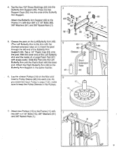
8. Attach a Pulley (10) to the indicated bracket on 11 the Frame (11) with a 3/8" x 1 3/4" Bolt (6), 3/8" Washer (61) and 3/8" Nylock Nut (1). 11 a 10 61___---t ----- 11. Attach a Pulley (10) to the indicated bracket on 10 the Frame (11) with a 3/8" x 1 3/4" Bolt (6), 3/8" Washer (61) and 3/8" Nylock Nut (1). -14- 11 10 61--1 6-1 '1 6 Attach a Pulley (10) to the Press Arm (27) with the 3/8" x 3" Bolt (64), a 3/8" Washer (61) and a 3/8" Nylock Nut (1). 8 ti Ii c 1 ° 27 15 . 10 61 \ 9 64----1 45 6-_,310 - 61-'1' 1 \ i 0! 10. Attach two Pulleys (10) to the ...
8. Attach a Pulley (10) to the indicated bracket on 11 the Frame (11) with a 3/8" x 1 3/4" Bolt (6), 3/8" Washer (61) and 3/8" Nylock Nut (1). 11 a 10 61___---t ----- 11. Attach a Pulley (10) to the indicated bracket on 10 the Frame (11) with a 3/8" x 1 3/4" Bolt (6), 3/8" Washer (61) and 3/8" Nylock Nut (1). -14- 11 10 61--1 6-1 '1 6 Attach a Pulley (10) to the Press Arm (27) with the 3/8" x 3" Bolt (64), a 3/8" Washer (61) and a 3/8" Nylock Nut (1). 8 ti Ii c 1 ° 27 15 . 10 61 \ 9 64----1 45 6-_,310 - 61-'1' 1 \ i 0! 10. Attach two Pulleys (10) to the ...

English Manual
Page 7
Attach a Pulley (10), with a Spacer (53) on each Cable is between the 3/8" x 2 3/4" Bolt and the indicated Pulley (10). - •..O"' 10 2 li o 1 28 1 , Lay the end of the 12 Frame (11). Find Cable #110290 (28). (Note: The part number of each side of it , inside the Frame (11) with a 3/8" x 2 3/4" Bolt Jk.Oi \ ,tonei 41 14 '3/0" VIV Ivy IlJtot% 1\1.4 I - : C6) 10 1 • -----2 11 13. Be sure that Cable 15 • #110290 (28) is printed on each step. The arrows indicate which hole to use in each side of it , inside the Frame (11) with a 3/8" x 2 3/4"...
Attach a Pulley (10), with a Spacer (53) on each Cable is between the 3/8" x 2 3/4" Bolt and the indicated Pulley (10). - •..O"' 10 2 li o 1 28 1 , Lay the end of the 12 Frame (11). Find Cable #110290 (28). (Note: The part number of each side of it , inside the Frame (11) with a 3/8" x 2 3/4" Bolt Jk.Oi \ ,tonei 41 14 '3/0" VIV Ivy IlJtot% 1\1.4 I - : C6) 10 1 • -----2 11 13. Be sure that Cable 15 • #110290 (28) is printed on each step. The arrows indicate which hole to use in each side of it , inside the Frame (11) with a 3/8" x 2 3/4"...

English Manual
Page 8
Hold a Pulley (10) in the "I "-Plates are at the top. Lay the eyelet end of the "U"-Bracket (17). Insert the threaded end of Cable #109461 (30) into the bottom of Cable #109461 (30) over a Pulley (10). Thread the two 5/16" Adjustment Nuts (12) halfway down the threads on the end of the Cable. 16. Slide the 5/16" Washer (51) onto the end of the Cable. Make sure that the "I "-Plates,(16) with a 3/8" x 1 3/4" Bolt (6) and 3/8" Nylock Nut (1). 18 12 51 19 c .1 %... ,.. - 17... Attach another Pulley (10) to the lowest holes in Cable #110290 (28) as shown. Attach the "U"-...
Hold a Pulley (10) in the "I "-Plates are at the top. Lay the eyelet end of the "U"-Bracket (17). Insert the threaded end of Cable #109461 (30) into the bottom of Cable #109461 (30) over a Pulley (10). Thread the two 5/16" Adjustment Nuts (12) halfway down the threads on the end of the Cable. 16. Slide the 5/16" Washer (51) onto the end of the Cable. Make sure that the "I "-Plates,(16) with a 3/8" x 1 3/4" Bolt (6) and 3/8" Nylock Nut (1). 18 12 51 19 c .1 %... ,.. - 17... Attach another Pulley (10) to the lowest holes in Cable #110290 (28) as shown. Attach the "U"-...
English Manual
Page 9
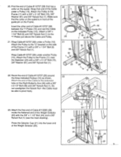
Attach a 3/8" x 1 3/4" Bolt (6) and 3/8" Nylock Nut (1) to the "I "-Plates (16) and rest the Cable on the indicated Pulley (10). Wrap Cable #110737 (29) under a Pulley (10). Find the end of Cable #110737 (29) that the collar on the eyelet is in front of tho tr' the extension tube on the Frame. Attach th,a and of the guide pin on the Right Butterfly Arm (46) with a 3/8" x 3 1/2" Bolt (15), 3/8" Washer (61) and 3/8" Nylock Nut (1). 22. Insert the other end of the Frame (11) with a 3/8" x 1 3/4" Bolt (6) and 3/8" Nylock Nut (1). Do not overtighten the Nylock Nut-the ...
Attach a 3/8" x 1 3/4" Bolt (6) and 3/8" Nylock Nut (1) to the "I "-Plates (16) and rest the Cable on the indicated Pulley (10). Wrap Cable #110737 (29) under a Pulley (10). Find the end of Cable #110737 (29) that the collar on the eyelet is in front of tho tr' the extension tube on the Frame. Attach th,a and of the guide pin on the Right Butterfly Arm (46) with a 3/8" x 3 1/2" Bolt (15), 3/8" Washer (61) and 3/8" Nylock Nut (1). 22. Insert the other end of the Frame (11) with a 3/8" x 1 3/4" Bolt (6) and 3/8" Nylock Nut (1). Do not overtighten the Nylock Nut-the ...

English Manual
Page 10
Attach the Butterfly Seat Rail (55) to the Frame (11) with two 1/4" x 3/4" Bolts (8) and 1/4" Lock Washers (7). 24 33 8 37 7 : 32 34 8 7 , , i !, ,i 55 54 25. Slide the bracket of the Leg Lever Pin, tap a 33 36 35 1/2" Hat Cap (39) onto the other end. Attach the Butterfly Seat Rail (55) to the Small Seat (54) with two 3/8" x 2 3/4" Bolts (2), 3/8" 25 Washers (61) and 3/8" Nylock Nuts (1). Insert the 27 Leg Lever Pin (38) through the Leg Lever and 1- Wet the ends of the Pad Tubes and the insides of the four Small Foam Pads (35) with the end of the Leg Lever (34) ...
Attach the Butterfly Seat Rail (55) to the Frame (11) with two 1/4" x 3/4" Bolts (8) and 1/4" Lock Washers (7). 24 33 8 37 7 : 32 34 8 7 , , i !, ,i 55 54 25. Slide the bracket of the Leg Lever Pin, tap a 33 36 35 1/2" Hat Cap (39) onto the other end. Attach the Butterfly Seat Rail (55) to the Small Seat (54) with two 3/8" x 2 3/4" Bolts (2), 3/8" 25 Washers (61) and 3/8" Nylock Nuts (1). Insert the 27 Leg Lever Pin (38) through the Leg Lever and 1- Wet the ends of the Pad Tubes and the insides of the four Small Foam Pads (35) with the end of the Leg Lever (34) ...

English Manual
Page 11
Make sure that all remaining parts is explained in USING THE SYSTEM 2, beginning on the same side. 57 19 56 o 56 Pin Grooves 29. The use of each cable a few times to make sure that the pin grooves are under the Weights and are tightened securely. IMPORTANT: If the cables are turned 20 so that the cables move smoothly, locate and correct the problem before using the SYSTEM 2, test the cables and pulleys. Place the nine Large Weights (56) and the Small Weight (57) 28 between the Weight Guides (19) by tipping the 19 Weights as shown (see the inset drawing). Before using...
Make sure that all remaining parts is explained in USING THE SYSTEM 2, beginning on the same side. 57 19 56 o 56 Pin Grooves 29. The use of each cable a few times to make sure that the pin grooves are under the Weights and are tightened securely. IMPORTANT: If the cables are turned 20 so that the cables move smoothly, locate and correct the problem before using the SYSTEM 2, test the cables and pulleys. Place the nine Large Weights (56) and the Small Weight (57) 28 between the Weight Guides (19) by tipping the 19 Weights as shown (see the inset drawing). Before using...

English Manual
Page 12
ATTACHING AND REMOVING THE PRESS SEAT RAIL The press seat rail should be attached as described above. For certain exercises, the press seat rail must be attached to the lower cable in the same manner. CHANGING THE WEIGHT SETTING Although the Large and Small Weights (56, 57) weigh 10 and 5 pounds respectively, the resis- The Ankle Strap (not shown) can be removed. IMPORTANT: The proper length of the Chain between the Lat Bar and the upper cable should be performed. See the Exercise Guide accompanying this owner's manual to see how the SYSTEM 2 should be determined by attaching ...
ATTACHING AND REMOVING THE PRESS SEAT RAIL The press seat rail should be attached as described above. For certain exercises, the press seat rail must be attached to the lower cable in the same manner. CHANGING THE WEIGHT SETTING Although the Large and Small Weights (56, 57) weigh 10 and 5 pounds respectively, the resis- The Ankle Strap (not shown) can be removed. IMPORTANT: The proper length of the Chain between the Lat Bar and the upper cable should be performed. See the Exercise Guide accompanying this owner's manual to see how the SYSTEM 2 should be determined by attaching ...
English Manual
Page 13
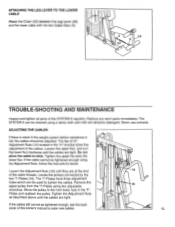
ADJUSTING THE CABLES If there is slack in the weight system before resistance is felt, the cables should be tightened enough, see the back cover of the cable threads. Loosen the upper Nut, and turn the lower Nut clockwise until the cables are at the end of this owner's manual to the next lower hole in the "U"-bracket allow the cable to tighten the cables. Locate the pulleys connected by the two "I "Plates and reattach the pulley. Move the pulley to order new cables. 12 16 \\ • 13 Do not allow fine adjustment of the SYSTEM 2 regularly. Loosen the Adjustment Nuts (12)...
ADJUSTING THE CABLES If there is slack in the weight system before resistance is felt, the cables should be tightened enough, see the back cover of the cable threads. Loosen the upper Nut, and turn the lower Nut clockwise until the cables are at the end of this owner's manual to the next lower hole in the "U"-bracket allow the cable to tighten the cables. Locate the pulleys connected by the two "I "Plates and reattach the pulley. Move the pulley to order new cables. 12 16 \\ • 13 Do not allow fine adjustment of the SYSTEM 2 regularly. Loosen the Adjustment Nuts (12)...

English Manual
Page 14
No. See the back cover of this manual for information about ordering replacement parts. 14 Description 1 012108 31 3/8" Nylock Nut 2 105329 8 3/8" x 2 3/4" Bolt 3 103087 2 Cable Clip 4 107048 1 Ankle Strap 5 013341 4 1/4" x 2 1/2 Bolt 6 013564 7 3/8" x 1 3/4" Bolt 7 014062 8 1/4" Lock Washer 8 013456 4 1/4" x 3/4" Bolt 9 111180 2 1/2" Brass Bushing 10 111175 16 Pulley 11 110678 1 Frame 12 101138 2 5/16" Adjustment Nut 13 110468 2 3/8" Lock Washer 14 012159 2 3/8" Nut 15 104049 6 3/8" x 3 1/2" Bolt 16 109875 2 "I .D. No. Chart Note: "#" indicates a non-illustrated part. ...
No. See the back cover of this manual for information about ordering replacement parts. 14 Description 1 012108 31 3/8" Nylock Nut 2 105329 8 3/8" x 2 3/4" Bolt 3 103087 2 Cable Clip 4 107048 1 Ankle Strap 5 013341 4 1/4" x 2 1/2 Bolt 6 013564 7 3/8" x 1 3/4" Bolt 7 014062 8 1/4" Lock Washer 8 013456 4 1/4" x 3/4" Bolt 9 111180 2 1/2" Brass Bushing 10 111175 16 Pulley 11 110678 1 Frame 12 101138 2 5/16" Adjustment Nut 13 110468 2 3/8" Lock Washer 14 012159 2 3/8" Nut 15 104049 6 3/8" x 3 1/2" Bolt 16 109875 2 "I .D. No. Chart Note: "#" indicates a non-illustrated part. ...

English Manual
Page 15
EXPLODED DRAWING Model No. 831.159213 Rev. 3/93 61 62 52 63 49 48 46 64 47 11 53 53 2 2 53 4-61 -45 1-4 1 11 9 39-©'. 3 39 ep 42 6 61 6 47 54 7 5 50 55 \ 7 _ 7 -6( 5 28 61 11 15 10 61 15 t" 30 6-1 1 41 44 6 1 5 17 I 51 31 27 0 21 1 6 5 23 60 24 56 7 61 14 #13 16 15 19 40 6 29 57 32 33 7 15 1 8 35 39 36 35 37 38 fe3 22 4 36 35 34 3 58 59 25 35 Specifications are subject to change without notice.
EXPLODED DRAWING Model No. 831.159213 Rev. 3/93 61 62 52 63 49 48 46 64 47 11 53 53 2 2 53 4-61 -45 1-4 1 11 9 39-©'. 3 39 ep 42 6 61 6 47 54 7 5 50 55 \ 7 _ 7 -6( 5 28 61 11 15 10 61 15 t" 30 6-1 1 41 44 6 1 5 17 I 51 31 27 0 21 1 6 5 23 60 24 56 7 61 14 #13 16 15 19 40 6 29 57 32 33 7 15 1 8 35 39 36 35 37 38 fe3 22 4 36 35 34 3 58 59 25 35 Specifications are subject to change without notice.

English Manual
Page 16
... be transmitted to state. Always mention this system is used for handling. SERVICE CENTERS and most SEARS RETAIL STORES. The MODEL NUMBER of the product (PROFORM® SYSTEM 2). 3. SEARS, ROEBUCK AND CO., DEPT. 817WA, 3333 BEVERLY ROAD, HOFFMAN ESTATES, IL 60179 Part No. 112676 3/93 © 1993 Sears, Roebuck and Co...
... be transmitted to state. Always mention this system is used for handling. SERVICE CENTERS and most SEARS RETAIL STORES. The MODEL NUMBER of the product (PROFORM® SYSTEM 2). 3. SEARS, ROEBUCK AND CO., DEPT. 817WA, 3333 BEVERLY ROAD, HOFFMAN ESTATES, IL 60179 Part No. 112676 3/93 © 1993 Sears, Roebuck and Co...
