

Uk Manual
Page 2
... ICON IP, Inc. 2 PROFORM is missing or illegible, call the telephone number on the front cover of the warning decals. TABLE OF CONTENTS WARNING DECAL PLACEMENT 2 IMPORTANT PRECAUTIONS 3 BEFORE YOU BEGIN 5 ASSEMBLY 6 HOW TO USE THE CHEST PULSE SENSOR 15 OPERATION AND ADJUSTMENT 16 HOW TO FOLD AND MOVE THE TREADMILL 23 TROUBLESHOOTING 25 EXERCISE GUIDELINES 28 PART LIST 30 EXPLODED DRAWING 32 ORDERING REPLACEMENT PARTS Back Cover RECYCLING INFORMATION Back Cover...
... ICON IP, Inc. 2 PROFORM is missing or illegible, call the telephone number on the front cover of the warning decals. TABLE OF CONTENTS WARNING DECAL PLACEMENT 2 IMPORTANT PRECAUTIONS 3 BEFORE YOU BEGIN 5 ASSEMBLY 6 HOW TO USE THE CHEST PULSE SENSOR 15 OPERATION AND ADJUSTMENT 16 HOW TO FOLD AND MOVE THE TREADMILL 23 TROUBLESHOOTING 25 EXERCISE GUIDELINES 28 PART LIST 30 EXPLODED DRAWING 32 ORDERING REPLACEMENT PARTS Back Cover RECYCLING INFORMATION Back Cover...
Uk Manual
Page 3
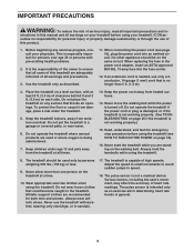
... operate the treadmill if the power cord or plug is damaged, or if the treadmill is not working properly.) 15. Always hold the handrails while using the treadmill. Do not wear loose clothes that blocks air openings. Adjust the speed in general. 3 Use the treadmill only as an exercise aid in determining heart rate trends in small increments to ensure that is not working properly. (See TROUBLESHOOTING on...
... operate the treadmill if the power cord or plug is damaged, or if the treadmill is not working properly.) 15. Always hold the handrails while using the treadmill. Do not wear loose clothes that blocks air openings. Adjust the speed in general. 3 Use the treadmill only as an exercise aid in determining heart rate trends in small increments to ensure that is not working properly. (See TROUBLESHOOTING on...

Uk Manual
Page 4
... any opening on the treadmill. 23. Never remove the motor hood un- Always unplug the power cord immediately after use . (See the drawing on page 23.) You must be performed by an authorized ser- When folding or moving the treadmill, make sure that the storage latch is properly assembled. (See ASSEMBLY on page 6, and HOW TO FOLD AND MOVE THE TREADMILL on page 5 for in-home use this treadmill in this manual.
... any opening on the treadmill. 23. Never remove the motor hood un- Always unplug the power cord immediately after use . (See the drawing on page 23.) You must be performed by an authorized ser- When folding or moving the treadmill, make sure that the storage latch is properly assembled. (See ASSEMBLY on page 6, and HOW TO FOLD AND MOVE THE TREADMILL on page 5 for in-home use this treadmill in this manual.

Uk Manual
Page 5
... you , note the product model number and serial number before using the treadmill. Accessory Tray Handrail Upright Walking Belt Foot Rail Idler Roller Adjustment Bolts Console Pulse Sensor Key/Clip Reset/Off Circuit Breaker Power Cord Platform Cushion 5 To help us . The 1300 ZLT treadmill offers an impressive array of other treadmills. If you ʼre not exercising, the unique treadmill can be folded up, requiring less than half the floor space of features designed to make...
... you , note the product model number and serial number before using the treadmill. Accessory Tray Handrail Upright Walking Belt Foot Rail Idler Roller Adjustment Bolts Console Pulse Sensor Key/Clip Reset/Off Circuit Breaker Power Cord Platform Cushion 5 To help us . The 1300 ZLT treadmill offers an impressive array of other treadmills. If you ʼre not exercising, the unique treadmill can be folded up, requiring less than half the floor space of features designed to make...
Uk Manual
Page 11
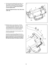
Start all four Screws, and then tighten them. Be careful not to avoid scratching the console. 9 Attach the Left Accessory Tray (103) with four 3 #8 x 1/2" Screws (3). Insert the Console Ground Wires (6) into the track in the console assembly (D). With the help of a second person, hold the handrail assembly (E) upside-down on a soft surface to pinch any wires. 10 D 6 E 102 F Track Ground Wires 11 D 3 Attach the Right Accessory Tray...
Start all four Screws, and then tighten them. Be careful not to avoid scratching the console. 9 Attach the Left Accessory Tray (103) with four 3 #8 x 1/2" Screws (3). Insert the Console Ground Wires (6) into the track in the console assembly (D). With the help of a second person, hold the handrail assembly (E) upside-down on a soft surface to pinch any wires. 10 D 6 E 102 F Track Ground Wires 11 D 3 Attach the Right Accessory Tray...
Uk Manual
Page 13
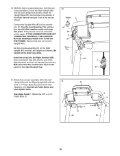
... TURN ON THE POWER. Set the console assembly (D) on the Right Upright (85) and the Left Upright (not shown). Start all six Patch Bolts, and then tighten them. The connectors should slide together easily and snap into the hole in the right Handrail Cap. 85 F 87 14. If they do not, turn one connector and try again. Attach the console assembly (D) to pinch any wires...
... TURN ON THE POWER. Set the console assembly (D) on the Right Upright (85) and the Left Upright (not shown). Start all six Patch Bolts, and then tighten them. The connectors should slide together easily and snap into the hole in the right Handrail Cap. 85 F 87 14. If they do not, turn one connector and try again. Attach the console assembly (D) to pinch any wires...
Uk Manual
Page 15
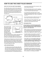
... and the chest pulse sensor is removed and the electrode areas are covered by high power lines or other sources. Note: If the chest pulse sensor does not function when positioned as is right-side-up. Insert the tab on the chest strap. For the console to display heart rate readings, the user must be within armʼs length of the console. • The chest pulse sensor is designed to work with...
... and the chest pulse sensor is removed and the electrode areas are covered by high power lines or other sources. Note: If the chest pulse sensor does not function when positioned as is right-side-up. Insert the tab on the chest strap. For the console to display heart rate readings, the user must be within armʼs length of the console. • The chest pulse sensor is designed to work with...
Uk Manual
Page 16
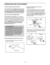
... in doubt as shown. DANGER: Improper connection of least resistance for electric current to the walking belt or the walking platform. Then, go to step 3. Plug the power cord into the socket on the treadmill. Screw Adapter Cover Pins Adapter Metal Clips 3. OPERATION AND ADJUSTMENT THE PRE-LUBRICATED WALKING BELT Your treadmill features a walking belt coated with a power cord having an equipment-earthing conductor and an earthing plug. Plug the indicated end of electric shock. UK...
... in doubt as shown. DANGER: Improper connection of least resistance for electric current to the walking belt or the walking platform. Then, go to step 3. Plug the power cord into the socket on the treadmill. Screw Adapter Cover Pins Adapter Metal Clips 3. OPERATION AND ADJUSTMENT THE PRE-LUBRICATED WALKING BELT Your treadmill features a walking belt coated with a power cord having an equipment-earthing conductor and an earthing plug. Plug the indicated end of electric shock. UK...

Uk Manual
Page 17
... or call the telephone number on the power, see page 22. As you use the information mode, see page 18. You can change the speed and incline of the treadmill with the consoleʼs stereo sound system. The iFit Live module allows you can even measure your workout results on the chest pulse sensor). To turn on the front cover of this manual. To use the stereo sound system...
... or call the telephone number on the power, see page 22. As you use the information mode, see page 18. You can change the speed and incline of the treadmill with the consoleʼs stereo sound system. The iFit Live module allows you can even measure your workout results on the chest pulse sensor). To turn on the front cover of this manual. To use the stereo sound system...

Uk Manual
Page 18
... selected speed setting. If you have selected a workout or the iFit training mode, press the Menu button to return to kilometers. See HOW TO TURN ON THE POWER at 2 Km/H. Locate the clip attached to turn off circuit breaker to move at the left. 2. PORTANT: In an emergency situation, the key can display speed and distance in a store. Each time the key is not pulled from the console, causing the walking belt...
... selected speed setting. If you have selected a workout or the iFit training mode, press the Menu button to return to kilometers. See HOW TO TURN ON THE POWER at 2 Km/H. Locate the clip attached to turn off circuit breaker to move at the left. 2. PORTANT: In an emergency situation, the key can display speed and distance in a store. Each time the key is not pulled from the console, causing the walking belt...
Uk Manual
Page 19
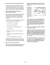
... the console. Measure your heart rate accurately. The console offers several display modes. Note: If you use the handgrip pulse sensor and the chest pulse sensor at the lowest setting when you may wear prematurely. Change the incline of the buttons, the incline will gradually change the incline of the treadmill, press the Incline increase or decrease button, or one of the treadmill as desired. Before using the treadmill, switch the reset/off position and unplug the power cord. The incline...
... the console. Measure your heart rate accurately. The console offers several display modes. Note: If you use the handgrip pulse sensor and the chest pulse sensor at the lowest setting when you may wear prematurely. Change the incline of the buttons, the incline will gradually change the incline of the treadmill, press the Incline increase or decrease button, or one of the treadmill as desired. Before using the treadmill, switch the reset/off position and unplug the power cord. The incline...

Uk Manual
Page 20
... adjust to the first speed and incline settings of the flashing segment indicates the speed setting for the next segment, the speed and/or incline will then slow to flash. Hold the handrails and begin to a stop . 20 One speed setting and one incline setting are programmed for consecutive segments. The walking belt will appear in the display. 3. If you have selected the manual mode, a workout, or the iFit training mode, press the Menu button...
... adjust to the first speed and incline settings of the flashing segment indicates the speed setting for the next segment, the speed and/or incline will then slow to flash. Hold the handrails and begin to a stop . 20 One speed setting and one incline setting are programmed for consecutive segments. The walking belt will appear in the display. 3. If you have selected the manual mode, a workout, or the iFit training mode, press the Menu button...

Uk Manual
Page 21
... are not supported). 4. Press the Enter button. Use the increase and decrease buttons next to www.iFit.com. Note: To use the iFit training mode, insert the iFit Live module into the console. Measure your wireless network and unlocks exciting new features. When you can manually override the setting by pressing the speed or incline buttons; In addition, if you manually change the speed or incline of the treadmill during the workout, the number of...
... are not supported). 4. Press the Enter button. Use the increase and decrease buttons next to www.iFit.com. Note: To use the iFit training mode, insert the iFit Live module into the console. Measure your wireless network and unlocks exciting new features. When you can manually override the setting by pressing the speed or incline buttons; In addition, if you manually change the speed or incline of the treadmill during the workout, the number of...

Uk Manual
Page 22
... plugged in the power cord, switch the reset/off the demo mode, press the Speed decrease button. If you remove the key, the displays will remain lit, although the buttons will show the total number of on and turn off the display demo mode. If the iFit Live module is selected, the following information will show the words "USB STATUS." Locate the audio wire and plug it into the console, and then release the Stop button. HOW TO USE...
... plugged in the power cord, switch the reset/off the demo mode, press the Speed decrease button. If you remove the key, the displays will remain lit, although the buttons will show the total number of on and turn off the display demo mode. If the iFit Live module is selected, the following information will show the words "USB STATUS." Locate the audio wire and plug it into the console, and then release the Stop button. HOW TO USE...
Uk Manual
Page 23
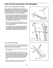
... the storage position. Place one of direct sunlight. Frame Handrail Wheel 23 Do not pull back on the wheels. Remove the key and unplug the power cord. Raise the frame until it back. Carefully move the treadmill without tipping it rolls freely on the frame. 3. If you fold it is resting in the storage position. Make sure that the latch knob is...
... the storage position. Place one of direct sunlight. Frame Handrail Wheel 23 Do not pull back on the wheels. Remove the key and unplug the power cord. Raise the frame until it back. Carefully move the treadmill without tipping it rolls freely on the frame. 3. If you fold it is resting in the storage position. Make sure that the latch knob is...

Uk Manual
Page 25
... the demo mode, hold down the Uprights (84, 85). c Tripped Reset PROBLEM: The power turns off circuit breaker located on . b. If the treadmill still will not run, please see the front cover of this manual. Remove the key from the console. TROUBLESHOOTING Most treadmill problems can be used if the treadmill is plugged in the bottom of the Belly Pan (75). There may be two Hood Screws (A) in . If an extension cord is needed, use...
... the demo mode, hold down the Uprights (84, 85). c Tripped Reset PROBLEM: The power turns off circuit breaker located on . b. If the treadmill still will not run, please see the front cover of this manual. Remove the key from the console. TROUBLESHOOTING Most treadmill problems can be used if the treadmill is plugged in the bottom of the Belly Pan (75). There may be two Hood Screws (A) in . If an extension cord is needed, use...

Uk Manual
Page 26
... the Motor Hood (62) off the walking platform. Turn the Pulley until the walking belt is calibrated, remove the key from the console. Make sure that is needed, use only a 3-conductor, 14-gauge (1 mm2) cord that the gap between the Magnet and 1/8 in . Reattach the Motor Hood (not shown) with the Reed Switch. Reattach the Hood Screws (not shown) if necessary. Run the Top View 48 treadmill for a correct speed reading. PROBLEM: The walking belt...
... the Motor Hood (62) off the walking platform. Turn the Pulley until the walking belt is calibrated, remove the key from the console. Make sure that is needed, use only a 3-conductor, 14-gauge (1 mm2) cord that the gap between the Magnet and 1/8 in . Reattach the Motor Hood (not shown) with the Reed Switch. Reattach the Hood Screws (not shown) if necessary. Run the Top View 48 treadmill for a correct speed reading. PROBLEM: The walking belt...

Uk Manual
Page 27
... a turn both idler roller bolts clock- Repeat until the walking belt is off-center, first remove the key and UNPLUG THE POWER CORD. Be careful not to keep the walk- When the walking belt is properly tightened. 27 If the walking belt slips when walked on the treadmill for a few minutes. Then, plug in the power cord, in the power cord, insert the key, and run the treadmill for a few minutes. PROBLEM: The walking belt is off the walking...
... a turn both idler roller bolts clock- Repeat until the walking belt is off-center, first remove the key and UNPLUG THE POWER CORD. Be careful not to keep the walk- When the walking belt is properly tightened. 27 If the walking belt slips when walked on the treadmill for a few minutes. Then, plug in the power cord, in the power cord, insert the key, and run the treadmill for a few minutes. PROBLEM: The walking belt is off the walking...
Uk Manual
Page 28
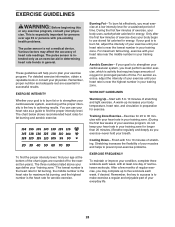
.... Training Zone Exercise-Exercise for 20 to five workouts each week, with 5 to burn fat, adjust the intensity of heart rate readings. For maximum fat burning, exercise with pre-existing health problems. The pulse sensor is near the highest number in preparation for energy. EXERCISE GUIDELINES WARNING: Before beginning this or any exercise program, consult your physician. This is intended only as a guide to find your heart rate near...
.... Training Zone Exercise-Exercise for 20 to five workouts each week, with 5 to burn fat, adjust the intensity of heart rate readings. For maximum fat burning, exercise with pre-existing health problems. The pulse sensor is near the highest number in preparation for energy. EXERCISE GUIDELINES WARNING: Before beginning this or any exercise program, consult your physician. This is intended only as a guide to find your heart rate near...

Uk Manual
Page 30
... 1 99 1 100 3 Description Storage Latch Chest Pulse Strap Audio Wire Right Foot Rail Frame Roller Bracket Roller Ground Wire Right Rear Foot Left Rear Foot Idler Roller Hex Key Motor Hood Handrail Cap Lift Frame Lift Frame Ground Wire Drive Motor Belt Drive Motor Controller Ground Wire Power Cord Power Cord Adapter Reset/Off Circuit Breaker Controller Reed Switch Reed Switch Clamp Belly Pan Wire Tie 8" Tie 15" Tie Releasable Tie Left Upright Cover Lower Handrail Cap Left Handrail Right Handrail Left Upright Right Upright Right Upright Cover Upright Wire Left Upright Spacer Base Cap Base...
... 1 99 1 100 3 Description Storage Latch Chest Pulse Strap Audio Wire Right Foot Rail Frame Roller Bracket Roller Ground Wire Right Rear Foot Left Rear Foot Idler Roller Hex Key Motor Hood Handrail Cap Lift Frame Lift Frame Ground Wire Drive Motor Belt Drive Motor Controller Ground Wire Power Cord Power Cord Adapter Reset/Off Circuit Breaker Controller Reed Switch Reed Switch Clamp Belly Pan Wire Tie 8" Tie 15" Tie Releasable Tie Left Upright Cover Lower Handrail Cap Left Handrail Right Handrail Left Upright Right Upright Right Upright Cover Upright Wire Left Upright Spacer Base Cap Base...


