
Uk Manual
Page 2
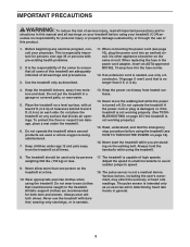
... actual size. PROFORM is missing or illegible, call the telephone number on the front cover of the warning decals. TABLE OF CONTENTS WARNING DECAL PLACEMENT 2 IMPORTANT PRECAUTIONS 3 BEFORE YOU BEGIN 5 ASSEMBLY 6 HOW TO USE THE CHEST PULSE SENSOR 15 OPERATION AND ADJUSTMENT 16 HOW TO FOLD AND MOVE THE TREADMILL 24 TROUBLESHOOTING 25 EXERCISE GUIDELINES 28 PART LIST 30 EXPLODED DRAWING 32 ORDERING REPLACEMENT PARTS Back Cover RECYCLING INFORMATION Back Cover WARNING...
... actual size. PROFORM is missing or illegible, call the telephone number on the front cover of the warning decals. TABLE OF CONTENTS WARNING DECAL PLACEMENT 2 IMPORTANT PRECAUTIONS 3 BEFORE YOU BEGIN 5 ASSEMBLY 6 HOW TO USE THE CHEST PULSE SENSOR 15 OPERATION AND ADJUSTMENT 16 HOW TO FOLD AND MOVE THE TREADMILL 24 TROUBLESHOOTING 25 EXERCISE GUIDELINES 28 PART LIST 30 EXPLODED DRAWING 32 ORDERING REPLACEMENT PARTS Back Cover RECYCLING INFORMATION Back Cover WARNING...
Uk Manual
Page 3
... treadmill at a time. 10. Never move the walking belt while the power is intended only as described. 11. The pulse sensor is turned off. Keep the treadmill indoors, away from the treadmill at least 8 ft. (2.4 m) of heart rate readings. structions in general. 3 IMPORTANT PRECAUTIONS WARNING: To reduce the risk of this manual and all warnings on your treadmill before using the treadmill (see page 16), plug the power cord...
... treadmill at a time. 10. Never move the walking belt while the power is intended only as described. 11. The pulse sensor is turned off. Keep the treadmill indoors, away from the treadmill at least 8 ft. (2.4 m) of heart rate readings. structions in general. 3 IMPORTANT PRECAUTIONS WARNING: To reduce the risk of this manual and all warnings on your treadmill before using the treadmill (see page 16), plug the power cord...
Uk Manual
Page 4
... INSTRUCTIONS 4 Always remove the key, unplug the power cord, and press the power switch into any object into the off position when the treadmill is intended for the location of the treadmill regularly. Never remove the motor hood un- When folding or moving the treadmill, make sure that the storage latch is running. Inspect and properly tighten all parts of the power switch.) 20. Never leave the treadmill unattended while it is properly assembled. (See ASSEMBLY...
... INSTRUCTIONS 4 Always remove the key, unplug the power cord, and press the power switch into any object into the off position when the treadmill is intended for the location of the treadmill regularly. Never remove the motor hood un- When folding or moving the treadmill, make sure that the storage latch is running. Inspect and properly tighten all parts of the power switch.) 20. Never leave the treadmill unattended while it is properly assembled. (See ASSEMBLY...

Uk Manual
Page 5
... review the drawing below and familiarize yourself with the labeled parts. For your workouts at home more enjoyable and effective. The 900 ZLT treadmill offers an impressive selection of this manual carefully before contacting us assist you for selecting the revolutionary PROFORM® 900 ZLT treadmill. ing this manual, please see the front cover of other treadmills. Tray Handrail Upright Walking Belt Foot Rail Console Pulse Sensor Key/Clip Power Switch Idler Roller Adjustment Bolts...
... review the drawing below and familiarize yourself with the labeled parts. For your workouts at home more enjoyable and effective. The 900 ZLT treadmill offers an impressive selection of this manual carefully before contacting us assist you for selecting the revolutionary PROFORM® 900 ZLT treadmill. ing this manual, please see the front cover of other treadmills. Tray Handrail Upright Walking Belt Foot Rail Console Pulse Sensor Key/Clip Power Switch Idler Roller Adjustment Bolts...
Uk Manual
Page 11
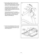
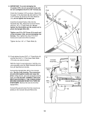
...). 11 Console Assembly 1 107 11 Slide the Right Upright Cover (86) onto the Right Upright (85). If necessary, press the 5/16" Cage Nut (38) back into place. Pull the Upright Wire out of the end of the Right Handrail. Remove the two #8 x 3/4" Screws (1). Set the console assembly face down on a soft surface to the Right Upright (85) with two 5/16" x 1" Flat Head Patch Bolts (14...
...). 11 Console Assembly 1 107 11 Slide the Right Upright Cover (86) onto the Right Upright (85). If necessary, press the 5/16" Cage Nut (38) back into place. Pull the Upright Wire out of the end of the Right Handrail. Remove the two #8 x 3/4" Screws (1). Set the console assembly face down on a soft surface to the Right Upright (85) with two 5/16" x 1" Flat Head Patch Bolts (14...
Uk Manual
Page 12
Connect the Upright Wire (87) to pinch the Upright Wire (87). IF YOU DO NOT CONNECT THE CONNECTORS PROPERLY, THE CONSOLE MAY BECOME DAMAGED WHEN YOU TURN ON THE POWER. First 29 12 87 Tighten one side is shown). Tighten the four 1/4" x 1" Patch Bolts (9). 13. 12. do not tighten the Screws yet. 107 Insert the Console Frame (102) into place. Connect the ground wires from the Upright Wire. Attach the Console Frame...
Connect the Upright Wire (87) to pinch the Upright Wire (87). IF YOU DO NOT CONNECT THE CONNECTORS PROPERLY, THE CONSOLE MAY BECOME DAMAGED WHEN YOU TURN ON THE POWER. First 29 12 87 Tighten one side is shown). Tighten the four 1/4" x 1" Patch Bolts (9). 13. 12. do not tighten the Screws yet. 107 Insert the Console Frame (102) into place. Connect the ground wires from the Upright Wire. Attach the Console Frame...
Uk Manual
Page 13
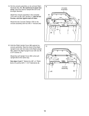
... the Right Upright Cover with two #8 x 3/4" Screws (1). Attach the two Console Clamps (105) to the Crossbar (107) with four #8 x 1" Screws (53). 14 87 Console Assembly 105 53 107 83 1 1 1 82 1 15. See steps 5 and 7. Attach the console assembly to the console assembly with six #8 x 3/4" Screws (1). Attach the Left Upright Cover (80) to pinch any wires. Tighten the 3/8" x 4" Patch Bolts (7) and the 3/8" x 1 1/2" Patch Bolts (3). 15 86 1 85 80 Console 1 Assembly 84 13 Attach the Right Upright Cover with...
... the Right Upright Cover with two #8 x 3/4" Screws (1). Attach the two Console Clamps (105) to the Crossbar (107) with four #8 x 1" Screws (53). 14 87 Console Assembly 105 53 107 83 1 1 1 82 1 15. See steps 5 and 7. Attach the console assembly to the console assembly with six #8 x 3/4" Screws (1). Attach the Left Upright Cover (80) to pinch any wires. Tighten the 3/8" x 4" Patch Bolts (7) and the 3/8" x 1 1/2" Patch Bolts (3). 15 86 1 85 80 Console 1 Assembly 84 13 Attach the Right Upright Cover with...
Uk Manual
Page 15
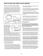
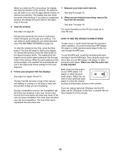
... the treadmill. 15 Note: If the chest pulse sensor does not function when positioned as described, move it to display heart rate readings, the user must be affected by magnetic interference caused by shallow ridges). The tab should be caused by medical conditions such as premature ventricular contractions (pvcs), tachycardia bursts, and arrhythmia. • The operation of the walking belt. the chest pulse sensor...
... the treadmill. 15 Note: If the chest pulse sensor does not function when positioned as described, move it to display heart rate readings, the user must be affected by magnetic interference caused by shallow ridges). The tab should be caused by medical conditions such as premature ventricular contractions (pvcs), tachycardia bursts, and arrhythmia. • The operation of the walking belt. the chest pulse sensor...
Uk Manual
Page 16
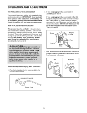
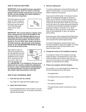
... you are plugging in the power cord in the adapter. HOW TO PLUG IN THE POWER CORD This product must be earthed. This product is properly earthed. Plug the power cord into an appropriate outlet that the screw is properly installed and earthed in doubt as shown. Then, go to step 3. Socket on the treadmill. OPERATION AND ADJUSTMENT THE PRE-LUBRICATED WALKING BELT Your treadmill features a walking belt coated with the...
... you are plugging in the power cord in the adapter. HOW TO PLUG IN THE POWER CORD This product must be earthed. This product is properly earthed. Plug the power cord into an appropriate outlet that the screw is properly installed and earthed in doubt as shown. Then, go to step 3. Socket on the treadmill. OPERATION AND ADJUSTMENT THE PRE-LUBRICATED WALKING BELT Your treadmill features a walking belt coated with the...
Uk Manual
Page 17
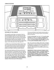
... iFit Live mode, you can display either metric or English measurements. To prevent damage to change the speed and incline of the treadmill with your wireless network through an effective exercise session. In addition, the console features fifteen onboard workouts-five calorie workouts, five timed workouts, and five distance workouts. To use the information mode, see page 22. To turn on the console, remove the plastic. CONSOLE DIAGRAM FEATURES OF THE CONSOLE The treadmill console...
... iFit Live mode, you can display either metric or English measurements. To prevent damage to change the speed and incline of the treadmill with your wireless network through an effective exercise session. In addition, the console features fifteen onboard workouts-five calorie workouts, five timed workouts, and five distance workouts. To use the information mode, see page 22. To turn on the console, remove the plastic. CONSOLE DIAGRAM FEATURES OF THE CONSOLE The treadmill console...
Uk Manual
Page 18
... incline setting. 5. The time will gradually adjust to flash in a store. To restart the walking belt, press the Start button or the Speed increase button. 4. Each time you hold down the button, the speed setting will change in the power cord and press the power switch into the console. Follow your clothes. Insert the key into the reset position, the demo mode is displayed in the display. See HOW TO TURN ON THE POWER above. 2. Press the Manual button on the treadmill...
... incline setting. 5. The time will gradually adjust to flash in a store. To restart the walking belt, press the Start button or the Speed increase button. 4. Each time you hold down the button, the speed setting will change in the power cord and press the power switch into the console. Follow your clothes. Insert the key into the reset position, the demo mode is displayed in the display. See HOW TO TURN ON THE POWER above. 2. Press the Manual button on the treadmill...
Uk Manual
Page 19
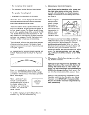
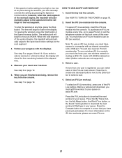
... menu). For the most accurate heart rate reading, continue to hold the pulse bar with your pulse is shown. If necessary, press the Home button again. Step onto the foot rails, press the Stop button, and adjust the incline of the treadmill 6. Next, remove the key from the console. When you exercise, the workout intensity level bar will not display your heart rate will show a profile of the incline settings of plastic from the metal contacts...
... menu). For the most accurate heart rate reading, continue to hold the pulse bar with your pulse is shown. If necessary, press the Home button again. Step onto the foot rails, press the Stop button, and adjust the incline of the treadmill 6. Next, remove the key from the console. When you exercise, the workout intensity level bar will not display your heart rate will show a profile of the incline settings of plastic from the metal contacts...
Uk Manual
Page 20
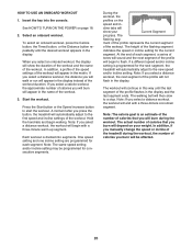
... USE AN ONBOARD WORKOUT 1. Press the Start button or the Speed increase button to flash. A moment after you press the button, the treadmill will automatically adjust to the first speed and incline settings of calories you burn will be programmed for each segment, a series of tones will begin with a three-minute cool-down segment. Note: If you manually change the speed or incline of the treadmill during the workout. One speed setting and one incline setting...
... USE AN ONBOARD WORKOUT 1. Press the Start button or the Speed increase button to flash. A moment after you press the button, the treadmill will automatically adjust to the first speed and incline settings of calories you burn will be programmed for each segment, a series of tones will begin with a three-minute cool-down segment. Note: If you manually change the speed or incline of the treadmill during the workout. One speed setting and one incline setting...
Uk Manual
Page 21
The walking belt will automatically adjust to the speed and incline settings for the next segment. See step 7 on page 18. 2. Note: To use an iFit Live workout, insert the iFit Live module into the console. Select a user. If more information on page 19. 6. Select an iFit Live workout. HOW TO USE AN IFIT LIVE WORKOUT 1. To stop the workout at any time, go to flash in the iFit Live main screen. When...
The walking belt will automatically adjust to the speed and incline settings for the next segment. See step 7 on page 18. 2. Note: To use an iFit Live workout, insert the iFit Live module into the console. Select a user. If more information on page 19. 6. Select an iFit Live workout. HOW TO USE AN IFIT LIVE WORKOUT 1. To stop the workout at any time, go to flash in the iFit Live main screen. When...
Uk Manual
Page 22
... the speed setting for the next segment. 6. The walking belt will begin to flash in the display. The end of the matrix represents the end of the workout. To use the MP3 jack, locate the included audio wire and plug it will show a track and the number of laps you are walking or running or it into a jack on page 19. Next, press the Play button...
... the speed setting for the next segment. 6. The walking belt will begin to flash in the display. The end of the matrix represents the end of the workout. To use the MP3 jack, locate the included audio wire and plug it will show a track and the number of laps you are walking or running or it into a jack on page 19. Next, press the Play button...

Uk Manual
Page 23
... button. To view distance in the display. Press the decrease button next to adjust the contrast. To send and receive workouts, workout logs, and updates, press the Enter button. To view distance in the power cord, press the power switch into the reset position, and insert the key into the console. While the demo mode is finished, the words TRANSFERS DONE will show the words WIFI STATUS. If a wireless iFit Live module is connected...
... button. To view distance in the display. Press the decrease button next to adjust the contrast. To send and receive workouts, workout logs, and updates, press the Enter button. To view distance in the power cord, press the power switch into the reset position, and insert the key into the console. While the demo mode is finished, the words TRANSFERS DONE will show the words WIFI STATUS. If a wireless iFit Live module is connected...
Uk Manual
Page 24
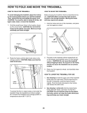
... not leave the treadmill in the storage position in the storage position. CAUTION: Do not move the treadmill without tipping it as described at the left ; Pivot the frame downward a few inches, and release the latch knob. 2. HOW TO FOLD AND MOVE THE TREADMILL HOW TO FOLD THE TREADMILL To avoid damaging the treadmill, adjust the incline to raise, lower, or move the treadmill over an uneven surface...
... not leave the treadmill in the storage position in the storage position. CAUTION: Do not move the treadmill without tipping it as described at the left ; Pivot the frame downward a few inches, and release the latch knob. 2. HOW TO FOLD AND MOVE THE TREADMILL HOW TO FOLD THE TREADMILL To avoid damaging the treadmill, adjust the incline to raise, lower, or move the treadmill over an uneven surface...
Uk Manual
Page 25
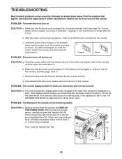
... extension cord is needed , see page 16). If the switch protrudes as shown, the switch has tripped. d. Note: A Phillips screwdriver with a shaft at least 5 in . c. Reinsert the key into the console. There may be solved by following the simple steps below. TROUBLESHOOTING Most treadmill problems can be three #8 x 2" Screws (A) in . Check the power switch located on SOLUTION: a. c Tripped Reset PROBLEM: The power turns off the demo mode, hold down the Uprights...
... extension cord is needed , see page 16). If the switch protrudes as shown, the switch has tripped. d. Note: A Phillips screwdriver with a shaft at least 5 in . c. Reinsert the key into the console. There may be solved by following the simple steps below. TROUBLESHOOTING Most treadmill problems can be three #8 x 2" Screws (A) in . Check the power switch located on SOLUTION: a. c Tripped Reset PROBLEM: The power turns off the demo mode, hold down the Uprights...
Uk Manual
Page 26
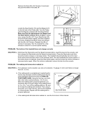
... move the Reed Switch slightly, and then retighten 73 the Screw. PROBLEM: The walking belt slows when walked on , see the front cover of this manual. 26 Idler Roller Bolts c. Turn the Pulley until the walking belt is aligned with the #8 x 3/4" Screws. Make sure that is calibrated, remove the key from the console. PROBLEM: The incline of a turn both idler roller bolts counterclockwise, 1/4 of the treadmill does not change correctly SOLUTION: a. Press the Stop button and then press the Incline increase or decrease button...
... move the Reed Switch slightly, and then retighten 73 the Screw. PROBLEM: The walking belt slows when walked on , see the front cover of this manual. 26 Idler Roller Bolts c. Turn the Pulley until the walking belt is aligned with the #8 x 3/4" Screws. Make sure that is calibrated, remove the key from the console. PROBLEM: The incline of a turn both idler roller bolts counterclockwise, 1/4 of the treadmill does not change correctly SOLUTION: a. Press the Stop button and then press the Incline increase or decrease button...
Uk Manual
Page 28
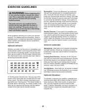
... minutes of your exercise until your heart rate is intended only as a guide to find your exercise program. For maximum fat burning, exercise with 5 to burn fat, adjust the intensity of your exercise until your heart rate is not a medical device. For aerobic exercise, adjust the intensity of stretching. The pulse sensor is near the middle number in general. The chart below shows recommended heart rates for successful results...
... minutes of your exercise until your heart rate is intended only as a guide to find your exercise program. For maximum fat burning, exercise with 5 to burn fat, adjust the intensity of your exercise until your heart rate is not a medical device. For aerobic exercise, adjust the intensity of stretching. The pulse sensor is near the middle number in general. The chart below shows recommended heart rates for successful results...

