
User Manual
Page 2
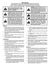
...of the equipment. If the unit should be thrown from the discharge chute. BECOME ALERT!!! WARNING: Snow throwers have exposed rotating parts, which can get caught in serious injury. Avoid loose fitting clothing that can cause severe injury from contact, or from material .... (a) Use an approved fuel container. 2. Adjust the collector housing height to observe the following safety instructions could result in moving parts. After striking a foreign object, stop the engine (motor), remove the wire from foreign objects that will improve footing on sloping surfaces...
...of the equipment. If the unit should be thrown from the discharge chute. BECOME ALERT!!! WARNING: Snow throwers have exposed rotating parts, which can get caught in serious injury. Avoid loose fitting clothing that can cause severe injury from contact, or from material .... (a) Use an approved fuel container. 2. Adjust the collector housing height to observe the following safety instructions could result in moving parts. After striking a foreign object, stop the engine (motor), remove the wire from foreign objects that will improve footing on sloping surfaces...
User Manual
Page 3
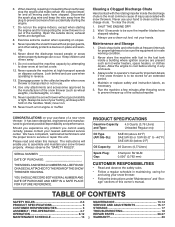
... SPECIFICATIONS 3 SERVICE AND ADJUSTMENTS 15-17 CUSTOMER RESPONSIBILITIES 3 STORAGE 17 ASSEMBLY / PRE-OPERATION 4-7 TROUBLESHOOTING 18 OPERATION 8-12 REPAIR PARTS 20-37 MAINTENANCE SCHEDULE 13 3 WARRANTY 40 When cleaning, repairing or inspecting the snow thrower, stop the engine and make certain... the collector/impeller and all moving parts have stopped rotating. 3. Open the outside doors; Never touch a hot engine or muffler. Maintenance and Storage 1. Maintain or...
... SPECIFICATIONS 3 SERVICE AND ADJUSTMENTS 15-17 CUSTOMER RESPONSIBILITIES 3 STORAGE 17 ASSEMBLY / PRE-OPERATION 4-7 TROUBLESHOOTING 18 OPERATION 8-12 REPAIR PARTS 20-37 MAINTENANCE SCHEDULE 13 3 WARRANTY 40 When cleaning, repairing or inspecting the snow thrower, stop the engine and make certain... the collector/impeller and all moving parts have stopped rotating. 3. Open the outside doors; Never touch a hot engine or muffler. Maintenance and Storage 1. Maintain or...

User Manual
Page 4
... will familiarize you with the exception of your new snow thrower. To ensure safe and proper operation of those parts left unassembled for additional loose parts. 4 Remove snow thrower from carton. 2. Your new snow thrower has been assembled at the factory with the... pallet. 4. Remove the two (2) plastic ties securing the upper handle to assemble or operate your snow thrower, all four corners of the product. PARTS PACKED SEPARATELY IN CARTON (1) AUGER CONTROL ROD (1) TRACTION DRIVE CONTROL ROD (1) DISCHARGE CHUTE (1) POWER CORD (198563) ROTATOR HEAD MOUNTING (1) MULTIWRENCH (...
... will familiarize you with the exception of your new snow thrower. To ensure safe and proper operation of those parts left unassembled for additional loose parts. 4 Remove snow thrower from carton. 2. Your new snow thrower has been assembled at the factory with the... pallet. 4. Remove the two (2) plastic ties securing the upper handle to assemble or operate your snow thrower, all four corners of the product. PARTS PACKED SEPARATELY IN CARTON (1) AUGER CONTROL ROD (1) TRACTION DRIVE CONTROL ROD (1) DISCHARGE CHUTE (1) POWER CORD (198563) ROTATOR HEAD MOUNTING (1) MULTIWRENCH (...

User Manual
Page 5
...spring into pivot bracket with loop opening down and insert top end of the spring as shown. 2. Install in lower holes in bag of parts. Slide rubber sleeve up rod and hook end of the chute rotator head to snow thrower and making adjustments to lower handle. Secure with ...rod positioned under left side of control panel, push rod down as shown. 1. Store the extra shear bolts, nuts and multi-wrench provided in parts bag in drive control bracket. Remove plastic tie securing rod to the operating position and tighten handle knobs securely. INSTALL SPEED CONTROL ROD (See Figs...
...spring into pivot bracket with loop opening down and insert top end of the spring as shown. 2. Install in lower holes in bag of parts. Slide rubber sleeve up rod and hook end of the chute rotator head to snow thrower and making adjustments to lower handle. Secure with ...rod positioned under left side of control panel, push rod down as shown. 1. Store the extra shear bolts, nuts and multi-wrench provided in parts bag in drive control bracket. Remove plastic tie securing rod to the operating position and tighten handle knobs securely. INSTALL SPEED CONTROL ROD (See Figs...

User Manual
Page 6
... CONTROL RETAINER LEVER SPRING PIN THREADED STUD CHUTE BRACKET ALIGN BEFORE TIGHTENING LOCKNUT FIG. 7 ROTATER HEAD MOUNTING BRACKET CHECK TIRE PRESSURE The tires on your parts bag may be used to align square and pin on threaded stud and tighten securely. Secure with loop opening toward front of mounting bracket. 4. Correct...
... CONTROL RETAINER LEVER SPRING PIN THREADED STUD CHUTE BRACKET ALIGN BEFORE TIGHTENING LOCKNUT FIG. 7 ROTATER HEAD MOUNTING BRACKET CHECK TIRE PRESSURE The tires on your parts bag may be used to align square and pin on threaded stud and tighten securely. Secure with loop opening toward front of mounting bracket. 4. Correct...

User Manual
Page 9
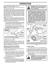
... shut-off valve is to stop engine. NOTE: Never use choke to "STOP" position. 2. Always operate the snow thrower with the engine at all moving parts to disengage. OFF FULL FIG. 11 TO CONTROL SNOW DISCHARGE (See Figs. 12 & 13) WARNING: Snow throwers have exposed rotating... parts, which snow is located beneath the fuel tank on discharge chute control lever and move de- 9 flector to start the engine. Move throttle control to ...
... shut-off valve is to stop engine. NOTE: Never use choke to "STOP" position. 2. Always operate the snow thrower with the engine at all moving parts to disengage. OFF FULL FIG. 11 TO CONTROL SNOW DISCHARGE (See Figs. 12 & 13) WARNING: Snow throwers have exposed rotating... parts, which snow is located beneath the fuel tank on discharge chute control lever and move de- 9 flector to start the engine. Move throttle control to ...

User Manual
Page 10
... snow thrower. It is engaged. Damage to desired position BEFORE engaging the traction drive control lever. When cleaning, repairing, or inspecting, make certain all moving parts have stopped. Be sure lever springs back and locks into the clip. • Make sure the discharge chute is controlled by the drive speed control...
... snow thrower. It is engaged. Damage to desired position BEFORE engaging the traction drive control lever. When cleaning, repairing, or inspecting, make certain all moving parts have stopped. Be sure lever springs back and locks into the clip. • Make sure the discharge chute is controlled by the drive speed control...
User Manual
Page 11
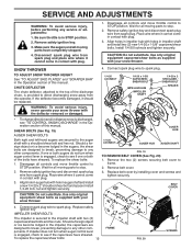
...in normal conditions, such as gravel, rocks or other debris, can easily be picked up and thrown by loosening the hex nuts, then moving parts to your snow thrower could result. After considerable use gasoline near an open flame. FIG. 18 BEFORE STARTING THE ENGINE TO START ENGINE CHECK ... system. Use fresh, clean, regular unleaded gasoline with gasoline. OPERATION TO ADJUST SKID PLATES (See Fig. 17) NOTE: The wrench provided in your parts bag may be used within 30 days to adjust the skid plates. Be sure both a 120 Volt A.C. Never use engine or carburetor cleaner products in...
...in normal conditions, such as gravel, rocks or other debris, can easily be picked up and thrown by loosening the hex nuts, then moving parts to your snow thrower could result. After considerable use gasoline near an open flame. FIG. 18 BEFORE STARTING THE ENGINE TO START ENGINE CHECK ... system. Use fresh, clean, regular unleaded gasoline with gasoline. OPERATION TO ADJUST SKID PLATES (See Fig. 17) NOTE: The wrench provided in your parts bag may be used within 30 days to adjust the skid plates. Be sure both a 120 Volt A.C. Never use engine or carburetor cleaner products in...

User Manual
Page 12
... the OFF position. Rotate choke control to FULL position. 4. Push the primer three (3) times. 7. Insert safety ignition key (packed separately in parts bag) into a three-hole grounded 120 Volt A.C. If temperature is not necessary. NOTE: Over priming may cause flooding, preventing the engine from ...SNOW THROWING TIPS • Always operate the snow thrower with the engine at full throttle. Insert safety ignition key (packed separately in parts bag) into ignition slot until it clicks. WARM START - Allow the engine to the OFF position. ELECTRIC STARTER Follow the steps ...
... the OFF position. Rotate choke control to FULL position. 4. Push the primer three (3) times. 7. Insert safety ignition key (packed separately in parts bag) into a three-hole grounded 120 Volt A.C. If temperature is not necessary. NOTE: Over priming may cause flooding, preventing the engine from ...SNOW THROWING TIPS • Always operate the snow thrower with the engine at full throttle. Insert safety ignition key (packed separately in parts bag) into ignition slot until it clicks. WARM START - Allow the engine to the OFF position. ELECTRIC STARTER Follow the steps ...
User Manual
Page 13
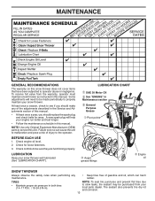
Some adjustments will help your snow thrower well lubricated (See "LUBRICATION CHART"). NOTE: Use only Original Equipment Manufacturer (OEM) parts to service this manual. Failure to do so can cause the unit to malfunction and pose a risk of gasoline and oil, which can ... slow leaks, tire sealant may be sure they are functioning properly. A new spark plug will need to be made periodically to properly maintain your local parts dealer. BEFORE EACH USE 1. Check engine oil level. 2. LUBRICATION CHART ➀ SAE 30 Motor Oil ➁ See "ENGINE" in Maintenance section ➂ ...
Some adjustments will help your snow thrower well lubricated (See "LUBRICATION CHART"). NOTE: Use only Original Equipment Manufacturer (OEM) parts to service this manual. Failure to do so can cause the unit to malfunction and pose a risk of gasoline and oil, which can ... slow leaks, tire sealant may be sure they are functioning properly. A new spark plug will need to be made periodically to properly maintain your local parts dealer. BEFORE EACH USE 1. Check engine oil level. 2. LUBRICATION CHART ➀ SAE 30 Motor Oil ➁ See "ENGINE" in Maintenance section ➂ ...
User Manual
Page 15
.... To replace the shear bolts: 1. BELT COVER CAUTION: Do not substitute. iCgonnitinoenckt sepyark plug wire to frame. 2. Disengage all moving parts to STOP position. CAUTION: Do not substitute. Use only original equipment capscrew/shear bolts as supplied with plug. 1. Wait for all controls...impeller shaft and install two (2) new 1/4-20 x 1-5/8" capscrew/shear bolts. If one or both of this manual. Disengage all moving parts have sheared. Place wire where it should be replaced. Align hole in auger hub with hole in contact with the deflector removed or ...
.... To replace the shear bolts: 1. BELT COVER CAUTION: Do not substitute. iCgonnitinoenckt sepyark plug wire to frame. 2. Disengage all moving parts to STOP position. CAUTION: Do not substitute. Use only original equipment capscrew/shear bolts as supplied with plug. 1. Wait for all controls...impeller shaft and install two (2) new 1/4-20 x 1-5/8" capscrew/shear bolts. If one or both of this manual. Disengage all moving parts have sheared. Place wire where it should be replaced. Align hole in auger hub with hole in contact with the deflector removed or ...
User Manual
Page 17
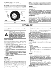
... alternative in the Service and Adjustments section of fuel gum deposits during storage. Store in axle and the wheel hub hole. Inspect moving parts for proper engine speed. Remove spark plug. 2. Rust and/or dirt in axle only. Pull recoil starter handle slowly a few times... altitudes up all nuts, bolts, screws, and pins are empty. • Never use plastic. sand lightly before storing in essential fuel system parts such as carburetor, fuel hose, or tank during storage. Also, alcohol blended fuels (called gasohol or using fuel stabilizer. of this manual). ...
... alternative in the Service and Adjustments section of fuel gum deposits during storage. Store in axle and the wheel hub hole. Inspect moving parts for proper engine speed. Remove spark plug. 2. Rust and/or dirt in axle only. Pull recoil starter handle slowly a few times... altitudes up all nuts, bolts, screws, and pins are empty. • Never use plastic. sand lightly before storing in essential fuel system parts such as carburetor, fuel hose, or tank during storage. Also, alcohol blended fuels (called gasohol or using fuel stabilizer. of this manual). ...
User Manual
Page 18
... centre/department. Stale fuel. 11. Fill fuel tank with fresh, clean gasoline. Reconnect spark plug wire. 2. Carburetor is in fuel. 5. Loose parts or damaged augers or impeller. 1. Replace damaged parts. If vibration remains, contact an authorized service centre/department. Frozen recoil starter. 1. Check / replace drive belt. Contact an authorized service centre/department...
... centre/department. Stale fuel. 11. Fill fuel tank with fresh, clean gasoline. Reconnect spark plug wire. 2. Carburetor is in fuel. 5. Loose parts or damaged augers or impeller. 1. Replace damaged parts. If vibration remains, contact an authorized service centre/department. Frozen recoil starter. 1. Check / replace drive belt. Contact an authorized service centre/department...
User Manual
Page 20
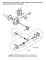
REPAIR PARTS SNOW THROWER - - inches. 1 inch = 25.4 mm IMPORTANT: Use only Original Equipment Manufacturer (O.E.M.) replacement parts. MODEL NUMBER XT8527ES (96192002302) AUGER HOUSING / IMPELLER ASSEMBLY 5 11 6 15 14 13 4 12 16 11 12 3 11 1 9 10 2 11 7 8 17 33 32 34 30 31 31 29 26 28 27 35 18 25 24 23 22 21 19 01.07.004-B 36 20 21 22 23 2 (EXPLODED) NOTE: All component dimensions given in U.S. Failure to do so could be hazardous, damage your snow thrower and void your warranty. 20
REPAIR PARTS SNOW THROWER - - inches. 1 inch = 25.4 mm IMPORTANT: Use only Original Equipment Manufacturer (O.E.M.) replacement parts. MODEL NUMBER XT8527ES (96192002302) AUGER HOUSING / IMPELLER ASSEMBLY 5 11 6 15 14 13 4 12 16 11 12 3 11 1 9 10 2 11 7 8 17 33 32 34 30 31 31 29 26 28 27 35 18 25 24 23 22 21 19 01.07.004-B 36 20 21 22 23 2 (EXPLODED) NOTE: All component dimensions given in U.S. Failure to do so could be hazardous, damage your snow thrower and void your warranty. 20

User Manual
Page 21
... 5/16−18 X .750 GEARBOX COVER LH NOTE: All component dimensions given in U.S. inches. 1 inch = 25.4 mm IMPORTANT: Use only Original Equipment Manufacturer (O.E.M.) replacement parts. MODEL NUMBER XT8527ES (96192002302) AUGER HOUSING / IMPELLER ASSEMBLY KEY NO. 1 2 3 4 5 6 7 8 9 10 11 12 13 14 15 16 17 18 19 20 21 22 23 24 25 26... 27 28 29 30 31 32 33 34 35 36 PART NO. Failure to do so could be hazardous, damage your snow thrower and void your...
... 5/16−18 X .750 GEARBOX COVER LH NOTE: All component dimensions given in U.S. inches. 1 inch = 25.4 mm IMPORTANT: Use only Original Equipment Manufacturer (O.E.M.) replacement parts. MODEL NUMBER XT8527ES (96192002302) AUGER HOUSING / IMPELLER ASSEMBLY KEY NO. 1 2 3 4 5 6 7 8 9 10 11 12 13 14 15 16 17 18 19 20 21 22 23 24 25 26... 27 28 29 30 31 32 33 34 35 36 PART NO. Failure to do so could be hazardous, damage your snow thrower and void your...

User Manual
Page 22
... - - Failure to do so could be hazardous, damage your snow thrower and void your warranty. 22 MODEL NUMBER XT8527ES (96192002302) AUGER HOUSING / IMPELLER ASSEMBLY 1 KEY NO. 1 2 3 4 PART NO. 404929X505 404932X479 72270505 155377 DESCRIPTION AUGER HOUSING 27 SCRAPER BAR CARRIAGE BOLT 5/16−18 X .625 NUT ...5/16−18 3 (5x) 4 (5x) 2 01.07.002-A 2 1 KEY NO. 1 2 PART NO. 420495X479 420496X479 DESCRIPTION AUGER 27 LH AUGER 27...
... - - Failure to do so could be hazardous, damage your snow thrower and void your warranty. 22 MODEL NUMBER XT8527ES (96192002302) AUGER HOUSING / IMPELLER ASSEMBLY 1 KEY NO. 1 2 3 4 PART NO. 404929X505 404932X479 72270505 155377 DESCRIPTION AUGER HOUSING 27 SCRAPER BAR CARRIAGE BOLT 5/16−18 X .625 NUT ...5/16−18 3 (5x) 4 (5x) 2 01.07.002-A 2 1 KEY NO. 1 2 PART NO. 420495X479 420496X479 DESCRIPTION AUGER 27 LH AUGER 27...

User Manual
Page 23
MODEL NUMBER XT8527ES (96192002302) AUGER HOUSING / IMPELLER ASSEMBLY 2 3 1 1 2 3 01.07.024-B KEY NO. 1 2 3 PART NO. 420478 411939 179582 DESCRIPTION AUGER BEARING BEARING PLUG SCREW 5/16−18 X 1.00 3 4 2 4 KEY PART NO. DESCRIPTION 1 174762X479 SKID PLATE LH 2 178777X479 SKID PLATE RH 3 72270506 CARRIAGE BOLT 5/16−...;18 X .75 3 01.11.001-A 1 4 751153 NUT 5/16−18 NOTE: All component dimensions given in U.S. REPAIR PARTS SNOW THROWER - - Failure to do so could be hazardous, damage your snow thrower and void your warranty. 23 NO. inches. 1 ...
MODEL NUMBER XT8527ES (96192002302) AUGER HOUSING / IMPELLER ASSEMBLY 2 3 1 1 2 3 01.07.024-B KEY NO. 1 2 3 PART NO. 420478 411939 179582 DESCRIPTION AUGER BEARING BEARING PLUG SCREW 5/16−18 X 1.00 3 4 2 4 KEY PART NO. DESCRIPTION 1 174762X479 SKID PLATE LH 2 178777X479 SKID PLATE RH 3 72270506 CARRIAGE BOLT 5/16−...;18 X .75 3 01.11.001-A 1 4 751153 NUT 5/16−18 NOTE: All component dimensions given in U.S. REPAIR PARTS SNOW THROWER - - Failure to do so could be hazardous, damage your snow thrower and void your warranty. 23 NO. inches. 1 ...

User Manual
Page 24
inches. 1 inch = 25.4 mm IMPORTANT: Use only Original Equipment Manufacturer (O.E.M.) replacement parts. MODEL NUMBER XT8527ES (96192002302) CONTROL PANEL / CHUTE 2 11 3 6 8 6 10 5 9 11 4 11 7 1 01.09.001-A KEY NO. 1 2 3 4 5 6 7 8 9 10 11 PART NO. 404770X505 178633X505 420325 179096X479 189713X428 128415 185600 72270505 191730 155415 179246 DESCRIPTION CHUTE WELDMENT DEFLECTOR WELDMENT DEFLECTOR SEAL STRAP KNOB ... NOTE: All component dimensions given in U.S. Failure to do so could be hazardous, damage your snow thrower and void your warranty. 24 REPAIR PARTS SNOW THROWER - -
inches. 1 inch = 25.4 mm IMPORTANT: Use only Original Equipment Manufacturer (O.E.M.) replacement parts. MODEL NUMBER XT8527ES (96192002302) CONTROL PANEL / CHUTE 2 11 3 6 8 6 10 5 9 11 4 11 7 1 01.09.001-A KEY NO. 1 2 3 4 5 6 7 8 9 10 11 PART NO. 404770X505 178633X505 420325 179096X479 189713X428 128415 185600 72270505 191730 155415 179246 DESCRIPTION CHUTE WELDMENT DEFLECTOR WELDMENT DEFLECTOR SEAL STRAP KNOB ... NOTE: All component dimensions given in U.S. Failure to do so could be hazardous, damage your snow thrower and void your warranty. 24 REPAIR PARTS SNOW THROWER - -
User Manual
Page 25
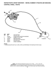
... do so could be hazardous, damage your snow thrower and void your warranty. 25 REPAIR PARTS SNOW THROWER - - inches. 1 inch = 25.4 mm IMPORTANT: Use only Original Equipment Manufacturer (O.E.M.) replacement parts. MODEL NUMBER XT8527ES (96192002302) CONTROL PANEL / CHUTE 2 2 *3 1 *6 KEY NO. 1 2 *3 *4 *5 *6 PART NO. 420337 17501010 420678 420677 420675 420674 *6 DESCRIPTION LEVER/CABLE ROTATOR ASSEMBLY SCREW 10...
... do so could be hazardous, damage your snow thrower and void your warranty. 25 REPAIR PARTS SNOW THROWER - - inches. 1 inch = 25.4 mm IMPORTANT: Use only Original Equipment Manufacturer (O.E.M.) replacement parts. MODEL NUMBER XT8527ES (96192002302) CONTROL PANEL / CHUTE 2 2 *3 1 *6 KEY NO. 1 2 *3 *4 *5 *6 PART NO. 420337 17501010 420678 420677 420675 420674 *6 DESCRIPTION LEVER/CABLE ROTATOR ASSEMBLY SCREW 10...

User Manual
Page 26
... 1 419798X479 LOOP HANDLE LH 12 3 419799X479 LOOP HANDLE RH 74780524 SCREW 5/16−18 X 1.50 4 751153 NUT 5/16−18 1 KEY NO. 1 2 3 4 PART NO. 419797X479 418313X479 150078 17000616 DESCRIPTION LOWER TUBE PIVOT SUPPORT BOLT 5/16−18 X .750 SCREW 3/8−16 X 1.00 2 4 3 4 4 01.05.004-B 4 NOTE: All ...component dimensions given in U.S. Failure to do so could be hazardous, damage your snow thrower and void your warranty. 26 REPAIR PARTS SNOW THROWER - - MODEL NUMBER XT8527ES (96192002302) HANDLES 4 4 3 2 01.08.004-B 3 4 4 3 3 KEY...
... 1 419798X479 LOOP HANDLE LH 12 3 419799X479 LOOP HANDLE RH 74780524 SCREW 5/16−18 X 1.50 4 751153 NUT 5/16−18 1 KEY NO. 1 2 3 4 PART NO. 419797X479 418313X479 150078 17000616 DESCRIPTION LOWER TUBE PIVOT SUPPORT BOLT 5/16−18 X .750 SCREW 3/8−16 X 1.00 2 4 3 4 4 01.05.004-B 4 NOTE: All ...component dimensions given in U.S. Failure to do so could be hazardous, damage your snow thrower and void your warranty. 26 REPAIR PARTS SNOW THROWER - - MODEL NUMBER XT8527ES (96192002302) HANDLES 4 4 3 2 01.08.004-B 3 4 4 3 3 KEY...


