
User Manual
Page 2
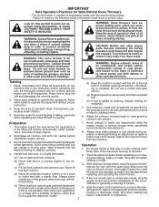
...order to prevent accidental starting when setting up spilled fuel. (h) If fuel is highly flammable 2. WARNING: Snow throwers have exposed rotating parts, which can Operation get caught in the manual(s) before operating this symbol to point out important safety precautions. CAUTION: Muffler and other ... nozzle in serious injury. Keep the area of operation clear of the equipment. Do not put hands or feet near or under rotating parts. remove the wire from a gasoline dispenser nozzle. WARNING: This snow thrower is complete. Read, understand and follow all times, until ...
...order to prevent accidental starting when setting up spilled fuel. (h) If fuel is highly flammable 2. WARNING: Snow throwers have exposed rotating parts, which can Operation get caught in the manual(s) before operating this symbol to point out important safety precautions. CAUTION: Muffler and other ... nozzle in serious injury. Keep the area of operation clear of the equipment. Do not put hands or feet near or under rotating parts. remove the wire from a gasoline dispenser nozzle. WARNING: This snow thrower is complete. Read, understand and follow all times, until ...
User Manual
Page 3
...your snow thrower properly. When cleaning, repairing or inspecting the snow thrower, stop the engine and make certain the collector/impeller and all moving parts have competent, well-trained technicians and the proper tools to assemble and maintain your nearest authorized service center. Never operate the snow thrower without... 3 CUSTOMER RESPONSIBILITIES 3 ASSEMBLY / PRE-OPERATION 4-6 OPERATION 7-12 MAINTENANCE SCHEDULE 13 MAINTENANCE 13-14 SERVICE AND ADJUSTMENTS 15-17 STORAGE 18 TROUBLESHOOTING 19 REPAIR PARTS 20-37 WARRANTY BACK COVER 3 Keep children and others away. 11.
...your snow thrower properly. When cleaning, repairing or inspecting the snow thrower, stop the engine and make certain the collector/impeller and all moving parts have competent, well-trained technicians and the proper tools to assemble and maintain your nearest authorized service center. Never operate the snow thrower without... 3 CUSTOMER RESPONSIBILITIES 3 ASSEMBLY / PRE-OPERATION 4-6 OPERATION 7-12 MAINTENANCE SCHEDULE 13 MAINTENANCE 13-14 SERVICE AND ADJUSTMENTS 15-17 STORAGE 18 TROUBLESHOOTING 19 REPAIR PARTS 20-37 WARRANTY BACK COVER 3 Keep children and others away. 11.
User Manual
Page 4
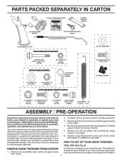
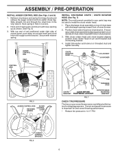
...TOOL BOX (See Fig. 8) REMOVE SNOW THROWER FROM CARTON A toolbox is 1. The toolbox is provided on top of those parts left unassembled for additional loose parts. PARTS PACKED SEPARATELY IN CARTON (1) FUEL STABILIZER PACKET (1) MULTIWRENCH (180684) (1) POWER CORD (198563) SAFTEY IGNITION KEY(S) (193071) (1)... your snow thrower. located on your new snow thrower. Reading the entire manual will assist you in the toolbox. 4 All parts such as necessary to ensure proper tightness. 2. Remove the two (2) screws securing the auger housing to the pallet. 6. Remove...
...TOOL BOX (See Fig. 8) REMOVE SNOW THROWER FROM CARTON A toolbox is 1. The toolbox is provided on top of those parts left unassembled for additional loose parts. PARTS PACKED SEPARATELY IN CARTON (1) FUEL STABILIZER PACKET (1) MULTIWRENCH (180684) (1) POWER CORD (198563) SAFTEY IGNITION KEY(S) (193071) (1)... your snow thrower. located on your new snow thrower. Reading the entire manual will assist you in the toolbox. 4 All parts such as necessary to ensure proper tightness. 2. Remove the two (2) screws securing the auger housing to the pallet. 6. Remove...
User Manual
Page 5
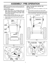
Install in lower holes in bag of parts. Remove plastic tie securring rod to the skid plates. Secure with retainer spring. UPPER HANDLE SPEED CONTROL ROD PLASTIC TIE INSTALL TRACTION DRIVE CONTROL ROD (...
Install in lower holes in bag of parts. Remove plastic tie securring rod to the skid plates. Secure with retainer spring. UPPER HANDLE SPEED CONTROL ROD PLASTIC TIE INSTALL TRACTION DRIVE CONTROL ROD (...
User Manual
Page 6
... INSTALL DISCHARGE CHUTE / CHUTE ROTATOR HEAD (See Fig. 7) NOTE: The multi-wrench provided in chute bracket. 3. Place discharge chute assembly on your parts bag may be used to 14-17 PSI. With chute rotator head and chute bracket aligned, position chute rotator head on underside of mounting bracket...of chute rotator head with discharge opening up as shown. (See Fig. 5) 3. Install 3/8 washer and locknut on rod and insert end of parts and retrieve the auger control rod from bag of rod into control arm with retainer spring. ASSEMBLY / PRE-OPERATION INSTALL AUGER CONTROL ROD (See ...
... INSTALL DISCHARGE CHUTE / CHUTE ROTATOR HEAD (See Fig. 7) NOTE: The multi-wrench provided in chute bracket. 3. Place discharge chute assembly on your parts bag may be used to 14-17 PSI. With chute rotator head and chute bracket aligned, position chute rotator head on underside of mounting bracket...of chute rotator head with discharge opening up as shown. (See Fig. 5) 3. Install 3/8 washer and locknut on rod and insert end of parts and retrieve the auger control rod from bag of rod into control arm with retainer spring. ASSEMBLY / PRE-OPERATION INSTALL AUGER CONTROL ROD (See ...
User Manual
Page 9
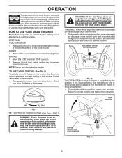
...control whenever you are starting a cold engine. WARNING: If the discharge chute or auger become clogged, shut-off engine and wait for all moving parts to throw snow farther. • To change the discharge chute position, press downward on the engine. set the deflector higher to stop the ... is in desired position. HIGH POSITION OFF FULL FIG. 9 TO CONTROL SNOW DISCHARGE (See Figs. 10 & 11) WARNING: Snow throwers have exposed rotating parts, which snow is located on discharge chute control lever and move de- ENGINE 1. TO USE CHOKE CONTROL (See Fig. 9) The choke control is to...
...control whenever you are starting a cold engine. WARNING: If the discharge chute or auger become clogged, shut-off engine and wait for all moving parts to throw snow farther. • To change the discharge chute position, press downward on the engine. set the deflector higher to stop the ... is in desired position. HIGH POSITION OFF FULL FIG. 9 TO CONTROL SNOW DISCHARGE (See Figs. 10 & 11) WARNING: Snow throwers have exposed rotating parts, which snow is located on discharge chute control lever and move de- ENGINE 1. TO USE CHOKE CONTROL (See Fig. 9) The choke control is to...
User Manual
Page 10
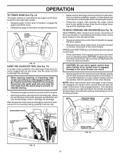
When cleaning, repairing, or inspecting, make certain all moving parts have stopped. Be sure lever springs back and locks into the clip. • Make sure the discharge chute is pointed in a safe direction (no vehicles, ...
When cleaning, repairing, or inspecting, make certain all moving parts have stopped. Be sure lever springs back and locks into the clip. • Make sure the discharge chute is pointed in a safe direction (no vehicles, ...
User Manual
Page 11
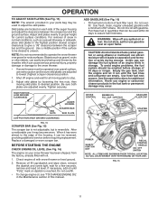
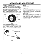
... or other debris, can easily be picked up and thrown by loosening the hex nuts, then moving skid plate to proper height for all moving parts to lowest (highest scraper clearance) position. 1. To avoid engine problems, the fuel system should be used to give a 1/8" clearance between the scraper ...16) The engine on each side of 30 days or longer. If necessary, add oil until the fuel lines and carburetor are located on your parts bag may be cleared is uneven. Be sure both plates are adjusted to stop. 2. WARNING: Wipe off engine and wait for current surface ...
... or other debris, can easily be picked up and thrown by loosening the hex nuts, then moving skid plate to proper height for all moving parts to lowest (highest scraper clearance) position. 1. To avoid engine problems, the fuel system should be used to give a 1/8" clearance between the scraper ...16) The engine on each side of 30 days or longer. If necessary, add oil until the fuel lines and carburetor are located on your parts bag may be cleared is uneven. Be sure both plates are adjusted to stop. 2. WARNING: Wipe off engine and wait for current surface ...
User Manual
Page 13
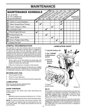
... and check belts for loose fasteners. 3. The belts are of operation and replace if necessary. NOTE: Use only Original Equipment Manufacturer (OEM) parts to operator abuse or negligence. Check engine oil level. 2. Replace belts if they are functioning properly. Using other local... parts dealer. Some adjustments will help your nearest dealer. LUBRICATION Keep your snow thrower. The belts on this snow thrower does not cover ...
... and check belts for loose fasteners. 3. The belts are of operation and replace if necessary. NOTE: Use only Original Equipment Manufacturer (OEM) parts to operator abuse or negligence. Check engine oil level. 2. Replace belts if they are functioning properly. Using other local... parts dealer. Some adjustments will help your nearest dealer. LUBRICATION Keep your snow thrower. The belts on this snow thrower does not cover ...
User Manual
Page 15
...cover. • Replace belt cover by installing cover and screws and tighten securely. Disconnect spark plug wire from the operator. Disengage all moving parts to the top of the bolts have completely stopped. 4. Should a foreign object or ice become lodged in contact with your snow thrower. .../ SHEAR BOLT AUGER HUB 1/4-20 LOCKNUT AUGER HUB AUGER SHAFT FIG. 18 TO REMOVE BELT COVER (See Fig. 19) 1. Disengage all moving parts to STOP position. Should a foreign object or ice become lodged in contact with holes in the OFF position. 2. Wait for all controls and ...
...cover. • Replace belt cover by installing cover and screws and tighten securely. Disconnect spark plug wire from the operator. Disengage all moving parts to the top of the bolts have completely stopped. 4. Should a foreign object or ice become lodged in contact with your snow thrower. .../ SHEAR BOLT AUGER HUB 1/4-20 LOCKNUT AUGER HUB AUGER SHAFT FIG. 18 TO REMOVE BELT COVER (See Fig. 19) 1. Disengage all moving parts to STOP position. Should a foreign object or ice become lodged in contact with holes in the OFF position. 2. Wait for all controls and ...
User Manual
Page 17
... lengthen the adjuster. Overspeeding the engine above the factory high speed setting can be affected at altitudes up to suspected carburetor problems, take your local parts dealer. Adjust until cable is not adjustable. KLIK PIN OUTER HOLE INNER HOLE ENGINE See engine manual. If you think the engine-governed high speed...
... lengthen the adjuster. Overspeeding the engine above the factory high speed setting can be affected at altitudes up to suspected carburetor problems, take your local parts dealer. Adjust until cable is not adjustable. KLIK PIN OUTER HOLE INNER HOLE ENGINE See engine manual. If you think the engine-governed high speed...
User Manual
Page 18
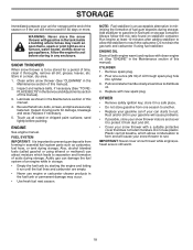
... blended fuels (called gasohol or using fuel stabilizer. NOTE: Fuel stabilizer is important to separation and formation of an engine while in essential fuel system parts such as carburetor, fuel hose, or tank during storage. Always follow the mix ratio found on a furnace, water heater, clothes dryer or gas appliance. CYLINDER... plug. SNOW THROWER When snow thrower is still warm. 18 Lubricate as on stabilizer container. Acidic gas can starts to reach the carburetor. Inspect moving parts for 30 days or more.
... blended fuels (called gasohol or using fuel stabilizer. NOTE: Fuel stabilizer is important to separation and formation of an engine while in essential fuel system parts such as carburetor, fuel hose, or tank during storage. Always follow the mix ratio found on a furnace, water heater, clothes dryer or gas appliance. CYLINDER... plug. SNOW THROWER When snow thrower is still warm. 18 Lubricate as on stabilizer container. Acidic gas can starts to reach the carburetor. Inspect moving parts for 30 days or more.
User Manual
Page 19
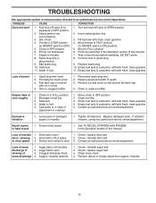
... line. 3. Move throttle to FAST position (or ON/OFF switch to OPEN position. 2. of swath. 3. Contact an authorized service center/department. Clogged discharge chute. 4. Loose parts or damaged augers or impeller. 1. Dirty or clogged muffler. 1. Reduce speed and width of drive speed 3. Stale fuel. 4. Replace damaged...
... line. 3. Move throttle to FAST position (or ON/OFF switch to OPEN position. 2. of swath. 3. Contact an authorized service center/department. Clogged discharge chute. 4. Loose parts or damaged augers or impeller. 1. Dirty or clogged muffler. 1. Reduce speed and width of drive speed 3. Stale fuel. 4. Replace damaged...
User Manual
Page 20
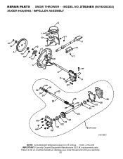
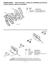
XT824ES (96192003302) AUGER HOUSING / IMPELLER ASSEMBLY 5 15 14 4 11 6 12 16 11 13 12 3 11 10 11 7 8 17 1 9 37 2 9 9 33 37 32 34 30 31 31 29 28 26 27 25 35 24 23 22 21 18 19 36 20 21 22 23 2 (EXPLODED) 01.07.026-C NOTE: All component dimensions given in U.S. Failure to do so could be hazardous, damage your snow thrower and void your warranty. 20 inches. 1 inch = 25.4 mm IMPORTANT: Use only Original Equipment Manufacturer (O.E.M.) replacement parts. MODEL NO. REPAIR PARTS SNOW THROWER - -
XT824ES (96192003302) AUGER HOUSING / IMPELLER ASSEMBLY 5 15 14 4 11 6 12 16 11 13 12 3 11 10 11 7 8 17 1 9 37 2 9 9 33 37 32 34 30 31 31 29 28 26 27 25 35 24 23 22 21 18 19 36 20 21 22 23 2 (EXPLODED) 01.07.026-C NOTE: All component dimensions given in U.S. Failure to do so could be hazardous, damage your snow thrower and void your warranty. 20 inches. 1 inch = 25.4 mm IMPORTANT: Use only Original Equipment Manufacturer (O.E.M.) replacement parts. MODEL NO. REPAIR PARTS SNOW THROWER - -
User Manual
Page 21
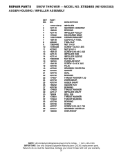
inches. 1 inch = 25.4 mm IMPORTANT: Use only Original Equipment Manufacturer (O.E.M.) replacement parts. MODEL NO. Failure to do so could be hazardous, damage your snow thrower and void your warranty. 21 XT824ES (96192003302) AUGER HOUSING / IMPELLER ASSEMBLY KEY NO. 1 2 3 4 5 6 7 8 9 10 11 12 13 14 15 16 17 18 19 20 21 22 23... 24 25 26 27 28 29 30 31 32 33 34 35 36 37 PART NO. 175321X479 427148 188909 427146 175322 178675X008...
inches. 1 inch = 25.4 mm IMPORTANT: Use only Original Equipment Manufacturer (O.E.M.) replacement parts. MODEL NO. Failure to do so could be hazardous, damage your snow thrower and void your warranty. 21 XT824ES (96192003302) AUGER HOUSING / IMPELLER ASSEMBLY KEY NO. 1 2 3 4 5 6 7 8 9 10 11 12 13 14 15 16 17 18 19 20 21 22 23... 24 25 26 27 28 29 30 31 32 33 34 35 36 37 PART NO. 175321X479 427148 188909 427146 175322 178675X008...
User Manual
Page 22
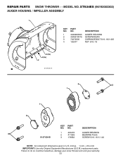
....4 mm IMPORTANT: Use only Original Equipment Manufacturer (O.E.M.) replacement parts. XT824ES (96192003302) AUGER HOUSING / IMPELLER ASSEMBLY 1 KEY NO. 1 2 3 4 PART NO. 404928X505 404931X479 72270505 155377 DESCRIPTION AUGER HOUSING SCRAPER BAR CARRIAGE BOLT 5/16−18 X .625 NUT 5/16−18 3 (5x) 4 (5x) 2 01.07.001-A 2 3 1 1 2 KEY PART NO. Failure to do so could be hazardous, damage...
....4 mm IMPORTANT: Use only Original Equipment Manufacturer (O.E.M.) replacement parts. XT824ES (96192003302) AUGER HOUSING / IMPELLER ASSEMBLY 1 KEY NO. 1 2 3 4 PART NO. 404928X505 404931X479 72270505 155377 DESCRIPTION AUGER HOUSING SCRAPER BAR CARRIAGE BOLT 5/16−18 X .625 NUT 5/16−18 3 (5x) 4 (5x) 2 01.07.001-A 2 3 1 1 2 KEY PART NO. Failure to do so could be hazardous, damage...
User Manual
Page 23
... THROWER - - inches. 1 inch = 25.4 mm IMPORTANT: Use only Original Equipment Manufacturer (O.E.M.) replacement parts. NO. XT824ES (96192003302) AUGER HOUSING / IMPELLER ASSEMBLY 2 1 KEY NO. 1 2 PART NO. 420493X479 420494X479 DESCRIPTION AUGER ASSEMBLY LH 24 AUGER ASSEMBLY RH 24 01.07.017-A 3 4 2 4 KEY PART NO. DESCRIPTION 1 174762X479 SKID PLATE LH 2 178777X479 SKID PLATE RH 3 72270506 CARRIAGE BOLT 5/16...
... THROWER - - inches. 1 inch = 25.4 mm IMPORTANT: Use only Original Equipment Manufacturer (O.E.M.) replacement parts. NO. XT824ES (96192003302) AUGER HOUSING / IMPELLER ASSEMBLY 2 1 KEY NO. 1 2 PART NO. 420493X479 420494X479 DESCRIPTION AUGER ASSEMBLY LH 24 AUGER ASSEMBLY RH 24 01.07.017-A 3 4 2 4 KEY PART NO. DESCRIPTION 1 174762X479 SKID PLATE LH 2 178777X479 SKID PLATE RH 3 72270506 CARRIAGE BOLT 5/16...
User Manual
Page 24
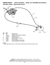
XT824ES (96192003302) CONTROL PANEL / DISCHARGE CHUTE 2 2 *3 1 *7 *6 KEY NO. 1 2 *3 *4 *5 *6 *7 PART NO. 428272 17501010 420678 405932 420675 428273 428310 DESCRIPTION LEVER/CABLE ROTATOR ASSEMBLY SCREW 10-24 X .625 ROTATOR HEAD ROTATOR PIVOT ... 01.09.010-B *5 NOTES: 1. inches. 1 inch = 25.4 mm IMPORTANT: Use only Original Equipment Manufacturer (O.E.M.) replacement parts. REPAIR PARTS SNOW THROWER - - ITEMS INDICATED WITH AN * ARE LISTED AS REFERENCE FOR SERVICE PARTS ONLY. NOTE: All component dimensions given in U.S. Failure to do so could be hazardous, damage your snow thrower and...
XT824ES (96192003302) CONTROL PANEL / DISCHARGE CHUTE 2 2 *3 1 *7 *6 KEY NO. 1 2 *3 *4 *5 *6 *7 PART NO. 428272 17501010 420678 405932 420675 428273 428310 DESCRIPTION LEVER/CABLE ROTATOR ASSEMBLY SCREW 10-24 X .625 ROTATOR HEAD ROTATOR PIVOT ... 01.09.010-B *5 NOTES: 1. inches. 1 inch = 25.4 mm IMPORTANT: Use only Original Equipment Manufacturer (O.E.M.) replacement parts. REPAIR PARTS SNOW THROWER - - ITEMS INDICATED WITH AN * ARE LISTED AS REFERENCE FOR SERVICE PARTS ONLY. NOTE: All component dimensions given in U.S. Failure to do so could be hazardous, damage your snow thrower and...
User Manual
Page 25
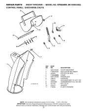
MODEL NO. REPAIR PARTS SNOW THROWER - - XT824ES (96192003302) CONTROL PANEL / DISCHARGE CHUTE 2 11 3 6 8 6 10 5 9 11 4 11 7 1 KEY PART NO. DESCRIPTION 01.09.001-B 1 420315X505 CHUTE WELDMENT 2 178633X505 DEFLECTOR WELDMENT 3 420325 DEFLECTOR SEAL 4 179096X479 STRAP 5 189713X428 KNOB BLACK 6 128415 POP RIVET 7 185600 SHOULDER BOLT 1/4&#... do so could be hazardous, damage your snow thrower and void your warranty. 25 inches. 1 inch = 25.4 mm IMPORTANT: Use only Original Equipment Manufacturer (O.E.M.) replacement parts. NO.
MODEL NO. REPAIR PARTS SNOW THROWER - - XT824ES (96192003302) CONTROL PANEL / DISCHARGE CHUTE 2 11 3 6 8 6 10 5 9 11 4 11 7 1 KEY PART NO. DESCRIPTION 01.09.001-B 1 420315X505 CHUTE WELDMENT 2 178633X505 DEFLECTOR WELDMENT 3 420325 DEFLECTOR SEAL 4 179096X479 STRAP 5 189713X428 KNOB BLACK 6 128415 POP RIVET 7 185600 SHOULDER BOLT 1/4&#... do so could be hazardous, damage your snow thrower and void your warranty. 25 inches. 1 inch = 25.4 mm IMPORTANT: Use only Original Equipment Manufacturer (O.E.M.) replacement parts. NO.
User Manual
Page 26
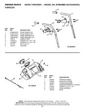
...to do so could be hazardous, damage your snow thrower and void your warranty. 26 XT824ES (96192003302) 5 KEY NO. 1 2 3 4 5 6 7 8 9 PART NO. 419800X479 419801X479 196944X007 196943X007 199513 74780512 74780524 751153 155415 5 DESCRIPTION PLOW HANDLE LH ...2 8 6 8 49 1 6 7 39 7 01.08.003-A 3 2 71 4 5 6 5 01.10.019 4 KEY PART NO. inches. 1 inch = 25.4 mm IMPORTANT: Use only Original Equipment Manufacturer (O.E.M.) replacement parts. NO. 1 429620 2 178668 3 180927 4 184471 5 175262 6 178770 7 183784 DESCRIPTION CONSOLE PANEL HEADLIGHT BEZEL FLOOD HEADLIGHT SHOULDER SCREW...
...to do so could be hazardous, damage your snow thrower and void your warranty. 26 XT824ES (96192003302) 5 KEY NO. 1 2 3 4 5 6 7 8 9 PART NO. 419800X479 419801X479 196944X007 196943X007 199513 74780512 74780524 751153 155415 5 DESCRIPTION PLOW HANDLE LH ...2 8 6 8 49 1 6 7 39 7 01.08.003-A 3 2 71 4 5 6 5 01.10.019 4 KEY PART NO. inches. 1 inch = 25.4 mm IMPORTANT: Use only Original Equipment Manufacturer (O.E.M.) replacement parts. NO. 1 429620 2 178668 3 180927 4 184471 5 175262 6 178770 7 183784 DESCRIPTION CONSOLE PANEL HEADLIGHT BEZEL FLOOD HEADLIGHT SHOULDER SCREW...


