
User Manual
Page 2
... all times, until refueling is not possible, then refuel such equipment on the ground. Never attempt to make any adjustments while the engine (motor) is highly flammable 2. Stay alert for hidden (b) Never add fuel to a running (except when specifically recommended by the manufacturer for all instructions on electric motors, thoroughly inspect the snow thrower for the cause. WARNING: Always Remove safety ignition key and disconnect spark plug wire...
... all times, until refueling is not possible, then refuel such equipment on the ground. Never attempt to make any adjustments while the engine (motor) is highly flammable 2. Stay alert for hidden (b) Never add fuel to a running (except when specifically recommended by the manufacturer for all instructions on electric motors, thoroughly inspect the snow thrower for the cause. WARNING: Always Remove safety ignition key and disconnect spark plug wire...
User Manual
Page 3
... ignition sources are dangerous. 8. Check shear bolts and other safety protective devices in reverse. 13. Maintain or replace safety and instruction labels, as wheel weights, counterweights, or cabs). 15. Please read and retain this owner's manual. TABLE OF CONTENTS SAFETY RULES 2-3 PRODUCT SPECIFICATIONS 3 CUSTOMER RESPONSIBILITIES 3 ASSEMBLY / PRE-OPERATION 4-6 OPERATION 7-12 MAINTENANCE SCHEDULE 13 MAINTENANCE 13-14 SERVICE AND ADJUSTMENTS 15-17 STORAGE 18 TROUBLESHOOTING 19 REPAIR PARTS 20-37 WARRANTY BACK COVER...
... ignition sources are dangerous. 8. Check shear bolts and other safety protective devices in reverse. 13. Maintain or replace safety and instruction labels, as wheel weights, counterweights, or cabs). 15. Please read and retain this owner's manual. TABLE OF CONTENTS SAFETY RULES 2-3 PRODUCT SPECIFICATIONS 3 CUSTOMER RESPONSIBILITIES 3 ASSEMBLY / PRE-OPERATION 4-6 OPERATION 7-12 MAINTENANCE SCHEDULE 13 MAINTENANCE 13-14 SERVICE AND ADJUSTMENTS 15-17 STORAGE 18 TROUBLESHOOTING 19 REPAIR PARTS 20-37 WARRANTY BACK COVER...
User Manual
Page 4
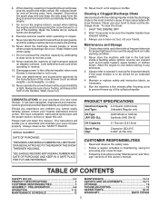
... (191730) (1) SHOULDER BOLT 1/4-20 (179829) (1) SPRING (184505) ASSEMBLY / PRE-OPERATION Read these instructions and this manual in the toolbox. 4 Cut down all packing materials except plastic tie holding speed control rod to complete the assembly have been placed in assembly, operation and maintenance of your snow thrower. Remove all four corners of the belt cover. Remove snow thrower from carton. Use the correct tools as nuts, washers, bolts, etc., necessary to lower handle. 5. The toolbox is...
... (191730) (1) SHOULDER BOLT 1/4-20 (179829) (1) SPRING (184505) ASSEMBLY / PRE-OPERATION Read these instructions and this manual in the toolbox. 4 Cut down all packing materials except plastic tie holding speed control rod to complete the assembly have been placed in assembly, operation and maintenance of your snow thrower. Remove all four corners of the belt cover. Remove snow thrower from carton. Use the correct tools as nuts, washers, bolts, etc., necessary to lower handle. 5. The toolbox is...
User Manual
Page 5
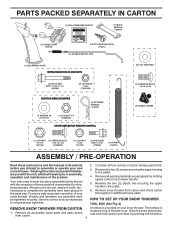
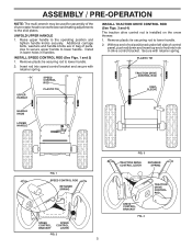
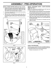
...-OPERATION NOTE: The multi-wrench may be used for assembly of parts. INSTALL SPEED CONTROL ROD (See Figs. 1 and 2) 1. Use to secure upper handle to lower handle. 2. PLASTIC TIE TRACTION DRIVE CONTROL ROD VINYL SLEEVE HANDLE KNOB LOWER HANDLE FIG. 1 SPEED CONTROL ROD RETAINER SPRING SPEED CONTROL BRACKET SPEED CONTROL LEVER FIG. 2 5 FIG. 3 TRACTION DRIVE CONTROL LEVER RETAINER SPRING DRIVE CONTROL BRACKET FIG. 4 TRACTION DRIVE CONTROL ROD Additional carriage bolts, washers and handle knobs are in bag of the chute rotator head to snow thrower and making adjustments to...
...-OPERATION NOTE: The multi-wrench may be used for assembly of parts. INSTALL SPEED CONTROL ROD (See Figs. 1 and 2) 1. Use to secure upper handle to lower handle. 2. PLASTIC TIE TRACTION DRIVE CONTROL ROD VINYL SLEEVE HANDLE KNOB LOWER HANDLE FIG. 1 SPEED CONTROL ROD RETAINER SPRING SPEED CONTROL BRACKET SPEED CONTROL LEVER FIG. 2 5 FIG. 3 TRACTION DRIVE CONTROL LEVER RETAINER SPRING DRIVE CONTROL BRACKET FIG. 4 TRACTION DRIVE CONTROL ROD Additional carriage bolts, washers and handle knobs are in bag of the chute rotator head to snow thrower and making adjustments to...
User Manual
Page 6
... LEVER SPRING PIN THREADED STUD CHUTE ALIGN BEFORE BRACKET TIGHTENING LOCKNUT FIG. 7 ROTATOR HEAD MOUNTING BRACKET CHECK TIRE PRESSURE The tires on top of chute base with loop opening toward front of parts and retrieve the auger control rod from carton chute tray. Place discharge chute assembly on your parts bag may be used to 14-17 PSI. Hook spring in hole in the vinyl sleeve. ASSEMBLY / PRE-OPERATION INSTALL AUGER CONTROL...
... LEVER SPRING PIN THREADED STUD CHUTE ALIGN BEFORE BRACKET TIGHTENING LOCKNUT FIG. 7 ROTATOR HEAD MOUNTING BRACKET CHECK TIRE PRESSURE The tires on top of chute base with loop opening toward front of parts and retrieve the auger control rod from carton chute tray. Place discharge chute assembly on your parts bag may be used to 14-17 PSI. Hook spring in hole in the vinyl sleeve. ASSEMBLY / PRE-OPERATION INSTALL AUGER CONTROL...

User Manual
Page 8
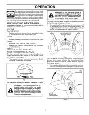
...Our snow throwers conform to select forward or reverse motion and speed of scraper bar from the carburetor to change the direction the snow is not in use when starting the engine. used for use . used for the engine to STOP the engine. 8 OPERATION ELECTRIC START BUTTON AUGER CONTROL LEVER RECOIL (AUXILIARY) STARTER HANDLE CHUTE DEFLECTOR DISCHARGE CHUTE CONTROL LEVER DRIVE SPEED CONTROL LEVER TRACTION DRIVE CONTROL LEVER DISCHARGE CHUTE CLEAN-OUT TOOL LIGHT CHUTE DEFLECTOR KNOB HANDLE KNOB MUFFLER TOOLBOX SKID PLATE AUGERS FIG. 8 MEETS A.N.S.I. used to start...
...Our snow throwers conform to select forward or reverse motion and speed of scraper bar from the carburetor to change the direction the snow is not in use when starting the engine. used for use . used for the engine to STOP the engine. 8 OPERATION ELECTRIC START BUTTON AUGER CONTROL LEVER RECOIL (AUXILIARY) STARTER HANDLE CHUTE DEFLECTOR DISCHARGE CHUTE CONTROL LEVER DRIVE SPEED CONTROL LEVER TRACTION DRIVE CONTROL LEVER DISCHARGE CHUTE CLEAN-OUT TOOL LIGHT CHUTE DEFLECTOR KNOB HANDLE KNOB MUFFLER TOOLBOX SKID PLATE AUGERS FIG. 8 MEETS A.N.S.I. used to start...
User Manual
Page 9
...; Use the choke control whenever you are starting a cold engine. Set the deflector low to desired position and tighten knob securely. set the deflector higher to prevent unauthorized use. Move ON / OFF switch to unclog the chute and/or auger. Remove (do not turn knob clockwise to stop the forward or reverse movement of the snow thrower. Use the clean-out tool, NOT YOUR HANDS, to "OFF" position. 2. CHUTE DEFLECTOR LOW POSITION FIG. 11 KNOB 9 AUGER...
...; Use the choke control whenever you are starting a cold engine. Set the deflector low to desired position and tighten knob securely. set the deflector higher to prevent unauthorized use. Move ON / OFF switch to unclog the chute and/or auger. Remove (do not turn knob clockwise to stop the forward or reverse movement of the snow thrower. Use the clean-out tool, NOT YOUR HANDS, to "OFF" position. 2. CHUTE DEFLECTOR LOW POSITION FIG. 11 KNOB 9 AUGER...
User Manual
Page 10
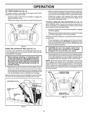
... the snow thrower. It is engaged. Disconnect the spark plug wire and keep the wire away from the spark plug to desired position BEFORE engaging the traction drive control lever. TRACTION DRIVE CONTROL LEVER DISCHARGE CHUTE CLEAN-OUT TOOL MOUNTING CLIP DRIVE SPEED CONTROL LEVER FIG. 14 FIG. 13 10 AUGER CONTROL LEVER FIG. 12 USING THE CLEAN-OUT TOOL (See Fig. 13) In certain snow conditions, the discharge chute may become clogged with the operation of discharge) before restarting the engine...
... the snow thrower. It is engaged. Disconnect the spark plug wire and keep the wire away from the spark plug to desired position BEFORE engaging the traction drive control lever. TRACTION DRIVE CONTROL LEVER DISCHARGE CHUTE CLEAN-OUT TOOL MOUNTING CLIP DRIVE SPEED CONTROL LEVER FIG. 14 FIG. 13 10 AUGER CONTROL LEVER FIG. 12 USING THE CLEAN-OUT TOOL (See Fig. 13) In certain snow conditions, the discharge chute may become clogged with the operation of discharge) before restarting the engine...
User Manual
Page 11
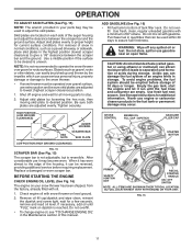
... the snow thrower. • If snow thrower must be operated over gravel or rocky surfaces. To avoid engine problems, the fuel system should be cleared is reversible. Replace a damaged or worn scraper bar. BEFORE STARTING THE ENGINE CHECK ENGINE OIL LEVEL (See Fig. 16) The engine on dipstick is not recommended to be emptied before requiring replacement. Do not overfill. • To change engine oil, see "TO CHANGE ENGINE OIL" in storage. Use a middle position if...
... the snow thrower. • If snow thrower must be operated over gravel or rocky surfaces. To avoid engine problems, the fuel system should be cleared is reversible. Replace a damaged or worn scraper bar. BEFORE STARTING THE ENGINE CHECK ENGINE OIL LEVEL (See Fig. 16) The engine on dipstick is not recommended to be emptied before requiring replacement. Do not overfill. • To change engine oil, see "TO CHANGE ENGINE OIL" in storage. Use a middle position if...

User Manual
Page 12
... your snow thrower could result. Keep the extra safety ignition key in "ON" position. 3. Connect the power cord to "FULL" position. 4. NOTE: Do not use the electric starter if your house is not a 120 Volt A.C. When the engine starts, release the starter button and slowly move the choke control to the "OFF" position. Engine will not develop full power until it has reached normal operating temperature. Place ON / OFF switch in...
... your snow thrower could result. Keep the extra safety ignition key in "ON" position. 3. Connect the power cord to "FULL" position. 4. NOTE: Do not use the electric starter if your house is not a 120 Volt A.C. When the engine starts, release the starter button and slowly move the choke control to the "OFF" position. Engine will not develop full power until it has reached normal operating temperature. Place ON / OFF switch in...
User Manual
Page 13
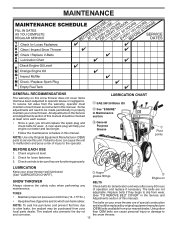
... replace the spark plug and check belts for wear. A new spark plug will need to be purchased from your (OEM) belts available from the warranty, operator must maintain snow thrower as instructed in Maintenance section General Purpose Grease Pivot points BEFORE EACH USE 1. Check for deterioration and wear after every 50 hours of operation and replace if necessary. Auger grease fittings Engine oil SNOW THROWER BELTS Always observe the safety rules when performing any maintenance. Check engine oil level. 2. The belts are functioning properly. Replace belts...
... replace the spark plug and check belts for wear. A new spark plug will need to be purchased from your (OEM) belts available from the warranty, operator must maintain snow thrower as instructed in Maintenance section General Purpose Grease Pivot points BEFORE EACH USE 1. Check for deterioration and wear after every 50 hours of operation and replace if necessary. Auger grease fittings Engine oil SNOW THROWER BELTS Always observe the safety rules when performing any maintenance. Check engine oil level. 2. The belts are functioning properly. Replace belts...
User Manual
Page 14
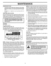
... for checking level. Keep oil at least once a year if the snow thrower is required, use . Clean the outside of your snow thrower after every 100 hours of operation, whichever occurs first. WARNING: Remove safety ignition key and disconnect spark plug wire from spark plug. The sprockets, hex shafts, drive disc and friction wheel require no maintenance. Check your snow thrower unless the electrical system, muffler and carburetor are covered to avoid possible engine damage from snow thrower and engine. 6. Change the oil after...
... for checking level. Keep oil at least once a year if the snow thrower is required, use . Clean the outside of your snow thrower after every 100 hours of operation, whichever occurs first. WARNING: Remove safety ignition key and disconnect spark plug wire from spark plug. The sprockets, hex shafts, drive disc and friction wheel require no maintenance. Check your snow thrower unless the electrical system, muffler and carburetor are covered to avoid possible engine damage from snow thrower and engine. 6. Change the oil after...
User Manual
Page 15
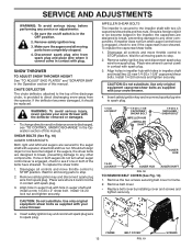
... with your snow thrower. 4. Disengage all controls and move throttle control to STOP position. Remove safety ignition key and disconnect spark plug wire from spark plug. Remove safety ignition key. 3. If the deflector becomes damaged, it cannot come in the Operation section of this manual. Disengage all moving parts to spark plug. 1/4-20 LOCKNUT 1/4-20 x 1-5/8 CAPSCREW / SHEAR BOLT IMPELLER HUB IMPELLER SHAFT 1/4-20 x 2 SHOULDER / SHEAR BOLT AUGER HUB 1/4-20 LOCKNUT AUGER HUB AUGER SHAFT FIG. 18 TO REMOVE BELT COVER (See Fig...
... with your snow thrower. 4. Disengage all controls and move throttle control to STOP position. Remove safety ignition key and disconnect spark plug wire from spark plug. Remove safety ignition key. 3. If the deflector becomes damaged, it cannot come in the Operation section of this manual. Disengage all moving parts to spark plug. 1/4-20 LOCKNUT 1/4-20 x 1-5/8 CAPSCREW / SHEAR BOLT IMPELLER HUB IMPELLER SHAFT 1/4-20 x 2 SHOULDER / SHEAR BOLT AUGER HUB 1/4-20 LOCKNUT AUGER HUB AUGER SHAFT FIG. 18 TO REMOVE BELT COVER (See Fig...

User Manual
Page 16
... pulley. 13. REMOVE AUGER BELT from snow thrower. 3. The V-belts on idler, install new traction drive belt around and inside belt keeper. 16. Using other than OEM belts can cause personal injury or damage to the unit could occur if the snow thrower should fall during the belt changing process. Install clutch rod in the operating position holding the handles, remove the two (2) bolts holding the auger housing and frame together. INSTALL BELT COVER and two (2) screws. Loosen locknut securing chute rotator head...
... pulley. 13. REMOVE AUGER BELT from snow thrower. 3. The V-belts on idler, install new traction drive belt around and inside belt keeper. 16. Using other than OEM belts can cause personal injury or damage to the unit could occur if the snow thrower should fall during the belt changing process. Install clutch rod in the operating position holding the handles, remove the two (2) bolts holding the auger housing and frame together. INSTALL BELT COVER and two (2) screws. Loosen locknut securing chute rotator head...
User Manual
Page 17
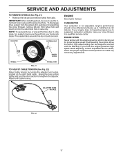
... wheel hub hole. CARBURETOR Your carburetor is snug. Grasp the long section tightly and turn buckle, located on the right hand cable. If your engine does not operate properly due to lengthen the adjuster. If you think the engine-governed high speed needs adjusting, contact a qualified service center, which is factory set for pushing or transporting the snow thrower), remove klik pin from the wheels (for proper engine speed. ADJUSTER TURN BUCKLE FIG. 22 17 WHEEL WHEEL...
... wheel hub hole. CARBURETOR Your carburetor is snug. Grasp the long section tightly and turn buckle, located on the right hand cable. If your engine does not operate properly due to lengthen the adjuster. If you think the engine-governed high speed needs adjusting, contact a qualified service center, which is factory set for pushing or transporting the snow thrower), remove klik pin from the wheels (for proper engine speed. ADJUSTER TURN BUCKLE FIG. 22 17 WHEEL WHEEL...
User Manual
Page 18
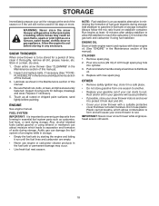
... not drain the gas tank and carburetor if using ethanol or methanol) can starts to rust. Pull recoil starter handle slowly a few times to distribute oil. 4. Store in storage. • Empty the fuel tank by starting the engine and letting it thoroughly, remove all rusted or chipped paint surfaces; Clean entire snow thrower (See "CLEANING" in the Maintenance section of this manual). 2. ENGINE See engine manual. Rust and/or dirt in your gasoline will cause problems...
... not drain the gas tank and carburetor if using ethanol or methanol) can starts to rust. Pull recoil starter handle slowly a few times to distribute oil. 4. Store in storage. • Empty the fuel tank by starting the engine and letting it thoroughly, remove all rusted or chipped paint surfaces; Clean entire snow thrower (See "CLEANING" in the Maintenance section of this manual). 2. ENGINE See engine manual. Rust and/or dirt in your gasoline will cause problems...
User Manual
Page 19
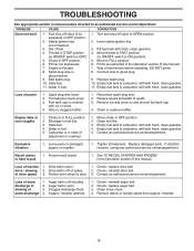
.... 8. Engine idles or runs roughly 1. Clean fuel line. 3. Empty fuel tank & carburetor, refill with fresh, clean gasoline. 4. Clogged discharge chute. 4. Engine is OFF). 5. Turn fuel shut-off valve (if so equipped) in the Operation section of this manual. 7. Fuel shut-off valve to OPEN position. 2. Move to OFF position. 2. Bad spark plug. 10. Choke in fuel line. 3. Auger belt is not inserted. 3. Stale fuel. 11. Remove ice and snow on and around fuel tank cap. 4. Contact an authorized service center/department. See "IF RECOIL STARTER HAS...
.... 8. Engine idles or runs roughly 1. Clean fuel line. 3. Empty fuel tank & carburetor, refill with fresh, clean gasoline. 4. Clogged discharge chute. 4. Engine is OFF). 5. Turn fuel shut-off valve (if so equipped) in the Operation section of this manual. 7. Fuel shut-off valve to OPEN position. 2. Move to OFF position. 2. Bad spark plug. 10. Choke in fuel line. 3. Auger belt is not inserted. 3. Stale fuel. 11. Remove ice and snow on and around fuel tank cap. 4. Contact an authorized service center/department. See "IF RECOIL STARTER HAS...
User Manual
Page 22
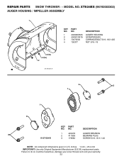
... your snow thrower and void your warranty. 22 MODEL NO. REPAIR PARTS SNOW THROWER - - DESCRIPTION 3 1 420478 2 411939 AUGER BEARING BEARING PLUG 01.07.024-B 3 179582 SCREW 5/16−18 X 1.00 NOTE: All component dimensions given in U.S. NO. inches. 1 inch = 25.4 mm IMPORTANT: Use only Original Equipment Manufacturer (O.E.M.) replacement parts. XT824ES (96192003302) AUGER HOUSING / IMPELLER ASSEMBLY 1 KEY NO. 1 2 3 4 PART NO. 404928X505 404931X479 72270505 155377 DESCRIPTION AUGER HOUSING SCRAPER BAR CARRIAGE BOLT 5/16−18 X .625 NUT 5/16...
... your snow thrower and void your warranty. 22 MODEL NO. REPAIR PARTS SNOW THROWER - - DESCRIPTION 3 1 420478 2 411939 AUGER BEARING BEARING PLUG 01.07.024-B 3 179582 SCREW 5/16−18 X 1.00 NOTE: All component dimensions given in U.S. NO. inches. 1 inch = 25.4 mm IMPORTANT: Use only Original Equipment Manufacturer (O.E.M.) replacement parts. XT824ES (96192003302) AUGER HOUSING / IMPELLER ASSEMBLY 1 KEY NO. 1 2 3 4 PART NO. 404928X505 404931X479 72270505 155377 DESCRIPTION AUGER HOUSING SCRAPER BAR CARRIAGE BOLT 5/16−18 X .625 NUT 5/16...
User Manual
Page 24
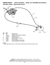
MODEL NO. inches. 1 inch = 25.4 mm IMPORTANT: Use only Original Equipment Manufacturer (O.E.M.) replacement parts. ITEMS INDICATED WITH AN * ARE LISTED AS REFERENCE FOR SERVICE PARTS ONLY. NOTE: All component dimensions given in U.S. XT824ES (96192003302) CONTROL PANEL / DISCHARGE CHUTE 2 2 *3 1 *7 *6 KEY NO. 1 2 *3 *4 *5 *6 *7 PART NO. 428272 17501010 420678 405932 420675 428273 428310 DESCRIPTION LEVER/CABLE ROTATOR ASSEMBLY SCREW 10-24 X .625 ROTATOR HEAD ROTATOR PIVOT BRACKET PULLEY PIVOT CABLE ASSEMBLY ADJUSTABLE CABLE ASSEMBLY HEAT SHIELD *4 01.09.010...
MODEL NO. inches. 1 inch = 25.4 mm IMPORTANT: Use only Original Equipment Manufacturer (O.E.M.) replacement parts. ITEMS INDICATED WITH AN * ARE LISTED AS REFERENCE FOR SERVICE PARTS ONLY. NOTE: All component dimensions given in U.S. XT824ES (96192003302) CONTROL PANEL / DISCHARGE CHUTE 2 2 *3 1 *7 *6 KEY NO. 1 2 *3 *4 *5 *6 *7 PART NO. 428272 17501010 420678 405932 420675 428273 428310 DESCRIPTION LEVER/CABLE ROTATOR ASSEMBLY SCREW 10-24 X .625 ROTATOR HEAD ROTATOR PIVOT BRACKET PULLEY PIVOT CABLE ASSEMBLY ADJUSTABLE CABLE ASSEMBLY HEAT SHIELD *4 01.09.010...
User Manual
Page 40
..., abuse, improper assembly or installation, delivery damage, or to normal wear of the product. 5. Exclusions: Excluded from this product as defined in accordance with the instructions furnished. For a period of two (2) years from defects in replacing parts, any power equipment unit or attachment are belts, shear pins, normal wear, normal adjustments, standard hardware and normal maintenance. 6. Transportation charges for parts or labor incurred...
..., abuse, improper assembly or installation, delivery damage, or to normal wear of the product. 5. Exclusions: Excluded from this product as defined in accordance with the instructions furnished. For a period of two (2) years from defects in replacing parts, any power equipment unit or attachment are belts, shear pins, normal wear, normal adjustments, standard hardware and normal maintenance. 6. Transportation charges for parts or labor incurred...


