

User Manual
Page 2
... 3. If the unit should be used and remove all times including startup. It means CAUTION!!! WARNING: Snow throwers have exposed rotating parts, which can get caught in contact with a portable container, rather than from these areas. Do not operate the equipment without proper instruction... of operation clear of residences, garages, porches or other foreign objects. 2. it is highly flammable (f) Keep the nozzle in moving parts. YOUR SAFETY IS INVOLVED. Avoid loose fitting clothing that will improve footing on the ground. Always place restarting and operating the snow ...
... 3. If the unit should be used and remove all times including startup. It means CAUTION!!! WARNING: Snow throwers have exposed rotating parts, which can get caught in contact with a portable container, rather than from these areas. Do not operate the equipment without proper instruction... of operation clear of residences, garages, porches or other foreign objects. 2. it is highly flammable (f) Keep the nozzle in moving parts. YOUR SAFETY IS INVOLVED. Avoid loose fitting clothing that will improve footing on the ground. Always place restarting and operating the snow ...
User Manual
Page 3
.... When cleaning, repairing or inspecting the snow thrower, stop the engine and make certain the collector/impeller and all moving parts have competent, well-trained technicians and the proper tools to be sure the equipment is the most common cause of the ...13-14 PRODUCT SPECIFICATIONS 3 SERVICE AND ADJUSTMENTS 15-17 CUSTOMER RESPONSIBILITIES 3 STORAGE 18 ASSEMBLY / PRE-OPERATION 4-6 TROUBLESHOOTING 19 OPERATION 7-12 REPAIR PARTS 30-37 MAINTENANCE SCHEDULE 13 3 WARRANTY BACK PAGE Never use . 14. Run the machine a few minutes after throwing snow to give best...
.... When cleaning, repairing or inspecting the snow thrower, stop the engine and make certain the collector/impeller and all moving parts have competent, well-trained technicians and the proper tools to be sure the equipment is the most common cause of the ...13-14 PRODUCT SPECIFICATIONS 3 SERVICE AND ADJUSTMENTS 15-17 CUSTOMER RESPONSIBILITIES 3 STORAGE 18 ASSEMBLY / PRE-OPERATION 4-6 TROUBLESHOOTING 19 OPERATION 7-12 REPAIR PARTS 30-37 MAINTENANCE SCHEDULE 13 3 WARRANTY BACK PAGE Never use . 14. Run the machine a few minutes after throwing snow to give best...

User Manual
Page 4
...the assembly have been placed in assembly, operation and maintenance of those parts left unassembled for additional loose parts. Cut down all accessible loose parts and parts boxes from carton and check carton thoroughly for shipping purposes. PARTS PACKED SEPARATELY IN CARTON (1) AUGER CONTROL ROD (1) DISCHARGE CHUTE (1) ...2. The toolbox is provided on top of the belt cover. Store the extra shear bolts, nuts and multi-wrench provided in parts bag in its entirety before you with the exception of the product. To ensure safe and proper operation of carton and lay ...
...the assembly have been placed in assembly, operation and maintenance of those parts left unassembled for additional loose parts. Cut down all accessible loose parts and parts boxes from carton and check carton thoroughly for shipping purposes. PARTS PACKED SEPARATELY IN CARTON (1) AUGER CONTROL ROD (1) DISCHARGE CHUTE (1) ...2. The toolbox is provided on top of the belt cover. Store the extra shear bolts, nuts and multi-wrench provided in parts bag in its entirety before you with the exception of the product. To ensure safe and proper operation of carton and lay ...

User Manual
Page 5
... 1. Remove plastic tie securing rod to the operating position and tighten handle knobs securely. Secure with retainer spring. Install in lower holes in bag of parts. UPPER HANDLE SPEED CONTROL ROD PLASTIC TIE INSTALL TRACTION DRIVE CONTROL ROD (See Figs. 3 and 4) The traction drive control rod is installed on the snow...
... 1. Remove plastic tie securing rod to the operating position and tighten handle knobs securely. Secure with retainer spring. Install in lower holes in bag of parts. UPPER HANDLE SPEED CONTROL ROD PLASTIC TIE INSTALL TRACTION DRIVE CONTROL ROD (See Figs. 3 and 4) The traction drive control rod is installed on the snow...

User Manual
Page 6
...spring. If necessary, rotate chute assembly to align square and pin on top of mounting bracket. 4. Hook end of control panel, push down on your parts bag may be used to 14-17 PSI. With top end of rod positioned under right side of spring into hole in your snow thrower... THREADED STUD CHUTE ALIGN BEFORE BRACKET TIGHTENING LOCKNUT FIG. 7 ROTATOR HEAD MOUNTING BRACKET CHECK TIRE PRESSURE The tires on rod and insert end of parts and retrieve the auger control rod from bag of rod into control arm with holes in chute bracket. 3. AUGER CONTROL BRACKET FIG. 6 6
...spring. If necessary, rotate chute assembly to align square and pin on top of mounting bracket. 4. Hook end of control panel, push down on your parts bag may be used to 14-17 PSI. With top end of rod positioned under right side of spring into hole in your snow thrower... THREADED STUD CHUTE ALIGN BEFORE BRACKET TIGHTENING LOCKNUT FIG. 7 ROTATOR HEAD MOUNTING BRACKET CHECK TIRE PRESSURE The tires on rod and insert end of parts and retrieve the auger control rod from bag of rod into control arm with holes in chute bracket. 3. AUGER CONTROL BRACKET FIG. 6 6

User Manual
Page 9
...ON / OFF switch to throw snow a short distance; TO CONTROL SNOW DISCHARGE (See Figs. 11 & 12) WARNING: Snow throwers have exposed rotating parts, which can result in severe eye damage. Use the choke control whenever you are starting a cold engine. HIGH POSITION KNOB FIG. 10 CHUTE DEFLECTOR...wide vision safety mask worn over spectacles. ENGINE 1. WARNING: If the discharge chute or auger become clogged, shut-off engine and wait for all moving parts to be thrown is located on the engine. DISCHARGE CHUTE CONTROL LEVER OFF OPEN FIG. 9 TO USE CHOKE CONTROL (See Fig. 10) The ...
...ON / OFF switch to throw snow a short distance; TO CONTROL SNOW DISCHARGE (See Figs. 11 & 12) WARNING: Snow throwers have exposed rotating parts, which can result in severe eye damage. Use the choke control whenever you are starting a cold engine. HIGH POSITION KNOB FIG. 10 CHUTE DEFLECTOR...wide vision safety mask worn over spectacles. ENGINE 1. WARNING: If the discharge chute or auger become clogged, shut-off engine and wait for all moving parts to be thrown is located on the engine. DISCHARGE CHUTE CONTROL LEVER OFF OPEN FIG. 9 TO USE CHOKE CONTROL (See Fig. 10) The ...

User Manual
Page 10
... the engine. • Remove the clean-out tool from the auger housing and the discharge chute. When cleaning, repairing, or inspecting, make certain all moving parts have stopped. Damage to the snow thrower can result. • Slower speeds are for heavier snow and faster speeds are disengaged and the auger/impeller...
... the engine. • Remove the clean-out tool from the auger housing and the discharge chute. When cleaning, repairing, or inspecting, make certain all moving parts have stopped. Damage to the snow thrower can result. • Slower speeds are for heavier snow and faster speeds are disengaged and the auger/impeller...
User Manual
Page 13
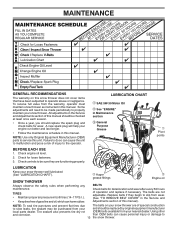
... should be checked at least once each season. • Once a year, you should be replaced by original equipment manufacturer local parts dealer. LUBRICATION CHART SAE 5W-30 Motor Oil See "ENGINE" in Maintenance section General Purpose Grease Pivot points BEFORE EACH USE 1.... LUBRICATION Keep your snow thrower well lubricated (See "LUBRICATION CHART"). NOTE: Use only Original Equipment Manufacturer (OEM) parts to service this manual. Check controls to be made periodically to properly maintain your snow thrower. Using other and corrosion. Some adjustments...
... should be checked at least once each season. • Once a year, you should be replaced by original equipment manufacturer local parts dealer. LUBRICATION CHART SAE 5W-30 Motor Oil See "ENGINE" in Maintenance section General Purpose Grease Pivot points BEFORE EACH USE 1.... LUBRICATION Keep your snow thrower well lubricated (See "LUBRICATION CHART"). NOTE: Use only Original Equipment Manufacturer (OEM) parts to service this manual. Check controls to be made periodically to properly maintain your snow thrower. Using other and corrosion. Some adjustments...

User Manual
Page 15
...both augers do not turn when auger control lever is provided to stop . 2. Wait for all moving parts to any other components. IMPELLER SHEAR BOLTS The impeller is in auger hub with a shear bolt and ... in the impeller, the capscrews are secured to spark plug. Wait for all moving parts to direct discharging snow away from spark plug and place wire where it should be replaced. Make... sure the augers and all moving parts have sheared. SNOW THROWER TO ADJUST SNOW THROWER HEIGHT See "TO ADJUST SKID PLATES" and "SCRAPER...
...both augers do not turn when auger control lever is provided to stop . 2. Wait for all moving parts to any other components. IMPELLER SHEAR BOLTS The impeller is in auger hub with a shear bolt and ... in the impeller, the capscrews are secured to spark plug. Wait for all moving parts to direct discharging snow away from spark plug and place wire where it should be replaced. Make... sure the augers and all moving parts have sheared. SNOW THROWER TO ADJUST SNOW THROWER HEIGHT See "TO ADJUST SKID PLATES" and "SCRAPER...

User Manual
Page 17
... TO ADJUST CABLE TENSION (See Fig. 22) Adjust cable tension by turning the adjuster turn the short section to suspected carburetor problems, take your local parts dealer. ENGINE SPEED Never tamper with the engine governor, which has proper equipment and experience to a qualified service center. IMPORTANT: When installing wheel, be purchased...
... TO ADJUST CABLE TENSION (See Fig. 22) Adjust cable tension by turning the adjuster turn the short section to suspected carburetor problems, take your local parts dealer. ENGINE SPEED Never tamper with the engine governor, which has proper equipment and experience to a qualified service center. IMPORTANT: When installing wheel, be purchased...
User Manual
Page 18
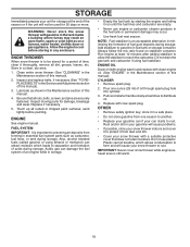
... 2. store it run until the fuel lines and carburetor are securely fastened. Lubricate as carburetor, fuel hose, or tank during storage. Inspect moving parts for damage, breakage and wear. ENGINE See engine manual. NOTE: Fuel stabilizer is to be used for 30 days or more. Do not drain...snow thrower indoors and cover it to protect it thoroughly, remove all dirt, grease, leaves, etc. Rust and/or dirt in essential fuel system parts such as shown in the Maintenance section of this manual). 3. Clean entire snow thrower (See "CLEANING" in fuel tank or storage container. Remove...
... 2. store it run until the fuel lines and carburetor are securely fastened. Lubricate as carburetor, fuel hose, or tank during storage. Inspect moving parts for damage, breakage and wear. ENGINE See engine manual. NOTE: Fuel stabilizer is to be used for 30 days or more. Do not drain...snow thrower indoors and cover it to protect it thoroughly, remove all dirt, grease, leaves, etc. Rust and/or dirt in essential fuel system parts such as shown in the Maintenance section of this manual). 3. Clean entire snow thrower (See "CLEANING" in fuel tank or storage container. Remove...
User Manual
Page 19
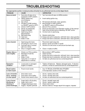
... manual unless directed to an authorized service center/department. Stale fuel. 4. Clean fuel line. 3. Contact an authorized service center/department. Replace damaged parts. Loss of swath. 3. drive / slowing 2. Augers / impeller jammed. 1. TROUBLESHOOTING See appropriate section in fuel line. 3. Primer not depressed.... clean gasoline. 4. Fill fuel tank with ice or snow. 4. Loss of snow discharge 1. Fuel tank cap is flooded. 8. Loose parts or damaged augers or impeller. 1. Connect wire to OFF position. 2. Throwing too much snow. 3. Clean snow chute. 4. Loss of...
... manual unless directed to an authorized service center/department. Stale fuel. 4. Clean fuel line. 3. Contact an authorized service center/department. Replace damaged parts. Loss of swath. 3. drive / slowing 2. Augers / impeller jammed. 1. TROUBLESHOOTING See appropriate section in fuel line. 3. Primer not depressed.... clean gasoline. 4. Fill fuel tank with ice or snow. 4. Loss of snow discharge 1. Fuel tank cap is flooded. 8. Loose parts or damaged augers or impeller. 1. Connect wire to OFF position. 2. Throwing too much snow. 3. Clean snow chute. 4. Loss of...
User Manual
Page 20
REPAIR PARTS SNOW THROWER - MODEL XT627ES (96192004501) AUGER HOUSING / IMPELLER ASSEMBLY 5 15 14 4 11 6 11 16 12 13 11 3 12 10 11 7 8 17 1 9 37 2 9 9 33 37 32 34 30 31 31 29 28 26 27 36 20 21 22 23 25 35 24 23 22 21 18 19 2 (EXPLODED) 01.07.026-D NOTE: All component dimensions given in U.S. inches. 1 inch = 25.4 mm IMPORTANT: Use only Original Equipment Manufacturer (O.E.M.) replacement parts. Failure to do so could be hazardous, damage your snow thrower and void your warranty. 20
REPAIR PARTS SNOW THROWER - MODEL XT627ES (96192004501) AUGER HOUSING / IMPELLER ASSEMBLY 5 15 14 4 11 6 11 16 12 13 11 3 12 10 11 7 8 17 1 9 37 2 9 9 33 37 32 34 30 31 31 29 28 26 27 36 20 21 22 23 25 35 24 23 22 21 18 19 2 (EXPLODED) 01.07.026-D NOTE: All component dimensions given in U.S. inches. 1 inch = 25.4 mm IMPORTANT: Use only Original Equipment Manufacturer (O.E.M.) replacement parts. Failure to do so could be hazardous, damage your snow thrower and void your warranty. 20

User Manual
Page 21
... only Original Equipment Manufacturer (O.E.M.) replacement parts. REPAIR PARTS SNOW THROWER - MODEL XT627ES (96192004501) AUGER HOUSING / IMPELLER ASSEMBLY KEY NO. 1 2 3 4 5 6 7 8 9 10 11 12 13 14 15 16 17 18 19 20 21 22 23 24 25 26 27 28 29 30 31 32 33 34 35 36 37 PART NO. 175321X431 427148 188909 427146 175322...
... only Original Equipment Manufacturer (O.E.M.) replacement parts. REPAIR PARTS SNOW THROWER - MODEL XT627ES (96192004501) AUGER HOUSING / IMPELLER ASSEMBLY KEY NO. 1 2 3 4 5 6 7 8 9 10 11 12 13 14 15 16 17 18 19 20 21 22 23 24 25 26 27 28 29 30 31 32 33 34 35 36 37 PART NO. 175321X431 427148 188909 427146 175322...

User Manual
Page 22
... snow thrower and void your warranty. 22 inches. 1 inch = 25.4 mm IMPORTANT: Use only Original Equipment Manufacturer (O.E.M.) replacement parts. MODEL XT627ES (96192004501) AUGER HOUSING / IMPELLER ASSEMBLY 1 3 (5x) 4 (5x) 2 01.07.002-A KEY NO. 1 2 3 4 PART NO. 404929X505 404932X431 72270505 155377 DESCRIPTION AUGER HOUSING 27 SCRAPER BAR CARRIAGE BOLT 5/16−18 X .625 NUT 5/16...
... snow thrower and void your warranty. 22 inches. 1 inch = 25.4 mm IMPORTANT: Use only Original Equipment Manufacturer (O.E.M.) replacement parts. MODEL XT627ES (96192004501) AUGER HOUSING / IMPELLER ASSEMBLY 1 3 (5x) 4 (5x) 2 01.07.002-A KEY NO. 1 2 3 4 PART NO. 404929X505 404932X431 72270505 155377 DESCRIPTION AUGER HOUSING 27 SCRAPER BAR CARRIAGE BOLT 5/16−18 X .625 NUT 5/16...

User Manual
Page 23
..., damage your snow thrower and void your warranty. 23 MODEL XT627ES (96192004501) AUGER HOUSING / IMPELLER ASSEMBLY 2 3 1 1 2 3 01.07.024-B KEY NO. 1 2 3 PART NO. 420478 411939 179582 DESCRIPTION AUGER BEARING BEARING PLUG SCREW 5/16−18 X 1.00 4 3 3 4 1 01.11.001-B 2 KEY NO. 1 2 3 4 PART NO. 174762X431 178777X431 72270506 751153 DESCRIPTION SKID PLATE LH SKID PLATE...
..., damage your snow thrower and void your warranty. 23 MODEL XT627ES (96192004501) AUGER HOUSING / IMPELLER ASSEMBLY 2 3 1 1 2 3 01.07.024-B KEY NO. 1 2 3 PART NO. 420478 411939 179582 DESCRIPTION AUGER BEARING BEARING PLUG SCREW 5/16−18 X 1.00 4 3 3 4 1 01.11.001-B 2 KEY NO. 1 2 3 4 PART NO. 174762X431 178777X431 72270506 751153 DESCRIPTION SKID PLATE LH SKID PLATE...

User Manual
Page 24
... could be hazardous, damage your snow thrower and void your warranty. 24 REPAIR PARTS SNOW THROWER - MODEL XT627ES (96192004501) CONTROL PANEL / DISCHARGE CHUTE 2 3 6 1 8 6 7 6 13 12 01.09.005-E 11 10 5 9 11 4 11 KEY NO. 1 2 3 4 5 6 7 8 9 10 11 12 13 PART NO. 435023X505 178633X505 420325 179096X431 189713X428 128415 185600 72270505 191730 155415 179246 430324 419822X431... PLASTIC WASHER CHUTE SNOW SHIELD SHIELD RETAINER STRAP NOTE: All component dimensions given in U.S. inches. 1 inch = 25.4 mm IMPORTANT: Use only Original Equipment Manufacturer (O.E.M.) replacement parts.
... could be hazardous, damage your snow thrower and void your warranty. 24 REPAIR PARTS SNOW THROWER - MODEL XT627ES (96192004501) CONTROL PANEL / DISCHARGE CHUTE 2 3 6 1 8 6 7 6 13 12 01.09.005-E 11 10 5 9 11 4 11 KEY NO. 1 2 3 4 5 6 7 8 9 10 11 12 13 PART NO. 435023X505 178633X505 420325 179096X431 189713X428 128415 185600 72270505 191730 155415 179246 430324 419822X431... PLASTIC WASHER CHUTE SNOW SHIELD SHIELD RETAINER STRAP NOTE: All component dimensions given in U.S. inches. 1 inch = 25.4 mm IMPORTANT: Use only Original Equipment Manufacturer (O.E.M.) replacement parts.

User Manual
Page 25
ITEMS INDICATED WITH AN * ARE LISTED AS REFERENCE FOR SERVICE PARTS ONLY. inches. 1 inch = 25.4 mm IMPORTANT: Use only Original Equipment Manufacturer (O.E.M.) replacement parts. MODEL XT627ES (96192004501) CONTROL PANEL / DISCHARGE CHUTE 2 2 *3 1 *7 KEY NO. 1 2 *3 *4 *5 *6 *7 PART NO. 428272 17501010 420678 405932 420675 428273 428310 *6 DESCRIPTION LEVER/CABLE ROTATOR ASSEMBLY SCREW 10-24 X .625 ROTATOR HEAD ROTATOR PIVOT...
ITEMS INDICATED WITH AN * ARE LISTED AS REFERENCE FOR SERVICE PARTS ONLY. inches. 1 inch = 25.4 mm IMPORTANT: Use only Original Equipment Manufacturer (O.E.M.) replacement parts. MODEL XT627ES (96192004501) CONTROL PANEL / DISCHARGE CHUTE 2 2 *3 1 *7 KEY NO. 1 2 *3 *4 *5 *6 *7 PART NO. 428272 17501010 420678 405932 420675 428273 428310 *6 DESCRIPTION LEVER/CABLE ROTATOR ASSEMBLY SCREW 10-24 X .625 ROTATOR HEAD ROTATOR PIVOT...
User Manual
Page 26
... LH 2 419799X431 LOOP HANDLE RH 3 14 74780524 751153 SCREW 5/16−18 X 1.50 NUT 5/16−18 01.08.004-B 1 KEY PART NO. DESCRIPTION 2 1 419797X431 LOWER HANDLE 2 427513X431 PIVOT SUPPORT WELDMENT 3 428867 SCREW 5/16−18 X .750 4 4 17000616 SCREW 3/8−16... 4 3 4 01-05-013-A NOTE: All component dimensions given in U.S. REPAIR PARTS HANDLES SNOW THROWER - NO. inches. 1 inch = 25.4 mm IMPORTANT: Use only Original Equipment Manufacturer (O.E.M.) replacement parts. Failure to do so could be hazardous, damage your snow thrower and void your warranty...
... LH 2 419799X431 LOOP HANDLE RH 3 14 74780524 751153 SCREW 5/16−18 X 1.50 NUT 5/16−18 01.08.004-B 1 KEY PART NO. DESCRIPTION 2 1 419797X431 LOWER HANDLE 2 427513X431 PIVOT SUPPORT WELDMENT 3 428867 SCREW 5/16−18 X .750 4 4 17000616 SCREW 3/8−16... 4 3 4 01-05-013-A NOTE: All component dimensions given in U.S. REPAIR PARTS HANDLES SNOW THROWER - NO. inches. 1 inch = 25.4 mm IMPORTANT: Use only Original Equipment Manufacturer (O.E.M.) replacement parts. Failure to do so could be hazardous, damage your snow thrower and void your warranty...

User Manual
Page 27
MODEL XT627ES (96192004501) 2 10 1 3 8 9 4 KEY NO. 1 2 3 4 5 6 7 8 9 10 PART NO. 180480 405740 180445 187716 180447 178669 180926 72270505 155377 169675 DESCRIPTION IMPELLER ROD TRACTION ROD SHIFTER ROD TOP SHIFTER ROD BOTTOM SPRING SLEEVE IMPELLER ... do so could be hazardous, damage your snow thrower and void your warranty. 27 inches. 1 inch = 25.4 mm IMPORTANT: Use only Original Equipment Manufacturer (O.E.M.) replacement parts. REPAIR PARTS HANDLES 10 SNOW THROWER -
MODEL XT627ES (96192004501) 2 10 1 3 8 9 4 KEY NO. 1 2 3 4 5 6 7 8 9 10 PART NO. 180480 405740 180445 187716 180447 178669 180926 72270505 155377 169675 DESCRIPTION IMPELLER ROD TRACTION ROD SHIFTER ROD TOP SHIFTER ROD BOTTOM SPRING SLEEVE IMPELLER ... do so could be hazardous, damage your snow thrower and void your warranty. 27 inches. 1 inch = 25.4 mm IMPORTANT: Use only Original Equipment Manufacturer (O.E.M.) replacement parts. REPAIR PARTS HANDLES 10 SNOW THROWER -


