
User Manual
Page 2
... for use a nozzle lock-open device. (g) Replace gasoline cap securely and wipe up , transporting, adjusting or making any adjustments while the engine (motor) is highly flammable 2. Preparation 1. gine. 3. remove the wire from these areas. Look for all times. 4. WARNING: Always Remove safety ignition key and disconnect spark plug wire and place it where it cannot contact plug in contact with the controls and the proper use snow thrower on surfaces above ground level...
... for use a nozzle lock-open device. (g) Replace gasoline cap securely and wipe up , transporting, adjusting or making any adjustments while the engine (motor) is highly flammable 2. Preparation 1. gine. 3. remove the wire from these areas. Look for all times. 4. WARNING: Always Remove safety ignition key and disconnect spark plug wire and place it where it cannot contact plug in contact with the controls and the proper use snow thrower on surfaces above ground level...
User Manual
Page 3
... RULES 2-3 PRODUCT SPECIFICATIONS 3 CUSTOMER RESPONSIBILITIES 3 ASSEMBLY / PRE-OPERATION 4-6 OPERATION 7-12 MAINTENANCE SCHEDULE 13 MAINTENANCE 13-14 SERVICE AND ADJUSTMENTS 15-17 STORAGE 18 TROUBLESHOOTING 19 REPAIR PARTS 20-37 WARRANTY BACK COVER 3 6. When cleaning, repairing or inspecting the snow thrower, stop the engine and make certain the collector/impeller and all moving parts have competent, well-trained technicians and the proper tools to clean out the discharge chute. Disconnect the spark plug wire and keep...
... RULES 2-3 PRODUCT SPECIFICATIONS 3 CUSTOMER RESPONSIBILITIES 3 ASSEMBLY / PRE-OPERATION 4-6 OPERATION 7-12 MAINTENANCE SCHEDULE 13 MAINTENANCE 13-14 SERVICE AND ADJUSTMENTS 15-17 STORAGE 18 TROUBLESHOOTING 19 REPAIR PARTS 20-37 WARRANTY BACK COVER 3 6. When cleaning, repairing or inspecting the snow thrower, stop the engine and make certain the collector/impeller and all moving parts have competent, well-trained technicians and the proper tools to clean out the discharge chute. Disconnect the spark plug wire and keep...
User Manual
Page 4
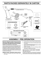
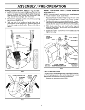
PARTS PACKED SEPARATELY IN CARTON (1) AUGER CONTROL ROD (1) DISCHARGE CHUTE (1) POWER CORD (198563) ROTATOR HEAD MOUNTING (1) MULTIWRENCH (180684) (3) RETAINER SPRINGS (169675) (2) FLAT WASHERS (2) CARRIAGE BOLTS 3/8-16 x 2.25 (1) WASHER 3/8 (19131316) (1) LOCKNUT 3/8 (73800600) SAFTEY IGNITION KEY(S) (422663) EXTRA SHEAR BOLTS AND NUTS (2) HANDLE KNOBS (2) SHEAR BOLTS 1/4-20 x 1-3/4 (192090) (2) LOCKNUTS 1/4-20 (73800400) ASSEMBLY / PRE-OPERATION Read these instructions and this manual in its entirety before you attempt to the pallet. 6. Remove the two (2) plastic ties ...
PARTS PACKED SEPARATELY IN CARTON (1) AUGER CONTROL ROD (1) DISCHARGE CHUTE (1) POWER CORD (198563) ROTATOR HEAD MOUNTING (1) MULTIWRENCH (180684) (3) RETAINER SPRINGS (169675) (2) FLAT WASHERS (2) CARRIAGE BOLTS 3/8-16 x 2.25 (1) WASHER 3/8 (19131316) (1) LOCKNUT 3/8 (73800600) SAFTEY IGNITION KEY(S) (422663) EXTRA SHEAR BOLTS AND NUTS (2) HANDLE KNOBS (2) SHEAR BOLTS 1/4-20 x 1-3/4 (192090) (2) LOCKNUTS 1/4-20 (73800400) ASSEMBLY / PRE-OPERATION Read these instructions and this manual in its entirety before you attempt to the pallet. 6. Remove the two (2) plastic ties ...
User Manual
Page 5
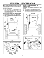
... be used for assembly of parts. Use to secure upper handle to lower handle. 2. Secure with retainer spring. Additional carriage bolts, washers and handle knobs are in bag of the chute rotator head to snow thrower and making adjustments to the skid plates. Remove plastic tie securing rod to lower handle. Remove plastic tie securring rod to the operating position and tighten handle knobs securely. Install in lower holes in drive control bracket. UPPER HANDLE SPEED CONTROL ROD...
... be used for assembly of parts. Use to secure upper handle to lower handle. 2. Secure with retainer spring. Additional carriage bolts, washers and handle knobs are in bag of the chute rotator head to snow thrower and making adjustments to the skid plates. Remove plastic tie securing rod to lower handle. Remove plastic tie securring rod to the operating position and tighten handle knobs securely. Install in lower holes in drive control bracket. UPPER HANDLE SPEED CONTROL ROD...
User Manual
Page 6
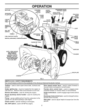
... your parts bag may be used to install the chute rotator head. 1. AUGER CONTROL BRACKET FIG. 6 6 Position chute rotator head over chute bracket. CONTROL ARM AUGER CONTROL ROD VINYL SLEEVE CHUTE ROTATOR HEAD 3/8 LOCKNUT 3/8 WASHER LOOP OPENING UP FIG. 5 AUGER CONTROL ROD RETAINER SPRING AUGER CONTROL LEVER PIN THREADED STUD CHUTE ALIGN BEFORE BRACKET TIGHTENING LOCKNUT FIG. 7 ROTATOR HEAD MOUNTING BRACKET CHECK TIRE PRESSURE The tires on rod and insert end of mounting bracket. 4. With chute rotator head and chute...
... your parts bag may be used to install the chute rotator head. 1. AUGER CONTROL BRACKET FIG. 6 6 Position chute rotator head over chute bracket. CONTROL ARM AUGER CONTROL ROD VINYL SLEEVE CHUTE ROTATOR HEAD 3/8 LOCKNUT 3/8 WASHER LOOP OPENING UP FIG. 5 AUGER CONTROL ROD RETAINER SPRING AUGER CONTROL LEVER PIN THREADED STUD CHUTE ALIGN BEFORE BRACKET TIGHTENING LOCKNUT FIG. 7 ROTATOR HEAD MOUNTING BRACKET CHECK TIRE PRESSURE The tires on rod and insert end of mounting bracket. 4. With chute rotator head and chute...
User Manual
Page 8
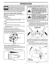
... standards of snow thrower. Primer - used to engage auger motion (throw snow). Safety ignition key - MUFFLER GASOLINE FILLER CAP CHOKE CONTROL SAFETY IGNITION KEY ON / OFF SWITCH PRIMER FUEL SHUT-OFF VALVE RECOIL (AUXILIARY) STARTER HANDLE OPERATION ELECTRIC START BUTTON POWER CORD PLUG AUGER CONTROL LEVER DISCHARGE CHUTE CONTROL LEVER DRIVE SPEED CONTROL LEVER CHUTE DEFLECTOR DISCHARGE CHUTE CLEAN-OUT TOOL TRACTION DRIVE CONTROL LEVER LIGHT CHUTE DEFLECTOR KNOB HANDLE KNOB NOTE: ITEMS ABOVE ARE SHOWN IN THEIR TYPICAL LOCATION ON THE ENGINE. Drive speed control lever - must be...
... standards of snow thrower. Primer - used to engage auger motion (throw snow). Safety ignition key - MUFFLER GASOLINE FILLER CAP CHOKE CONTROL SAFETY IGNITION KEY ON / OFF SWITCH PRIMER FUEL SHUT-OFF VALVE RECOIL (AUXILIARY) STARTER HANDLE OPERATION ELECTRIC START BUTTON POWER CORD PLUG AUGER CONTROL LEVER DISCHARGE CHUTE CONTROL LEVER DRIVE SPEED CONTROL LEVER CHUTE DEFLECTOR DISCHARGE CHUTE CLEAN-OUT TOOL TRACTION DRIVE CONTROL LEVER LIGHT CHUTE DEFLECTOR KNOB HANDLE KNOB NOTE: ITEMS ABOVE ARE SHOWN IN THEIR TYPICAL LOCATION ON THE ENGINE. Drive speed control lever - must be...
User Manual
Page 9
... in the OPEN position. set the deflector higher to stop engine. Always operate the snow thrower with the fuel shut-off engine and wait for all times including startup. Use the clean-out tool, NOT YOUR HANDS, to stop throwing snow. Use the choke control whenever you are starting a cold engine. NOTE: Never use . Keep the area of operation clear of any adjustments or repairs. Be sure lever springs back and locks into the eyes...
... in the OPEN position. set the deflector higher to stop engine. Always operate the snow thrower with the fuel shut-off engine and wait for all times including startup. Use the clean-out tool, NOT YOUR HANDS, to stop throwing snow. Use the choke control whenever you are starting a cold engine. NOTE: Never use . Keep the area of operation clear of any adjustments or repairs. Be sure lever springs back and locks into the eyes...
User Manual
Page 10
... position. This will lock the auger control lever in the engaged position. OPERATION TO THROW SNOW (See Fig. 13) The auger rotation is controlled by the auger control lever located on the right side handle. • Squeeze auger control lever to handle to engage the auger and throw snow. • Release the auger control lever to prevent accidental starting. • Release the auger control lever and shut off the engine. • Remove the clean-out tool from it's mounting clip. Use the clean-out tool...
... position. This will lock the auger control lever in the engaged position. OPERATION TO THROW SNOW (See Fig. 13) The auger rotation is controlled by the auger control lever located on the right side handle. • Squeeze auger control lever to handle to engage the auger and throw snow. • Release the auger control lever to prevent accidental starting. • Release the auger control lever and shut off the engine. • Remove the clean-out tool from it's mounting clip. Use the clean-out tool...
User Manual
Page 11
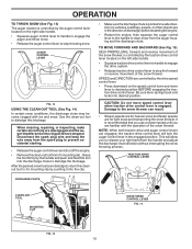
... SWITCH CHOKE CONTROL RECOIL (AUXILIARY) STARTER HANDLE GASOLINE FILLER CAP ENGINE OIL FILL CAP / DIPSTICK STARTER BUTTON SAFETY IGNITION KEY PRIMER FUEL SHUT-OFF VALVE POWER CORD PLUG NOTE: ALL ITEMS ARE SHOWN IN THEIR TYPICAL LOCATION. NOTE: It is uneven. Tighten securely. Skid plates are adjusted to the edge of the auger housing and adjust the clearance between the scraper bar and the ground. HIGH POSITION (LOW GROUND CLEARANCE) HEX NUTS AUGER HOUSING SCRAPER BAR SKID PLATE LOW POSITION (HIGH...
... SWITCH CHOKE CONTROL RECOIL (AUXILIARY) STARTER HANDLE GASOLINE FILLER CAP ENGINE OIL FILL CAP / DIPSTICK STARTER BUTTON SAFETY IGNITION KEY PRIMER FUEL SHUT-OFF VALVE POWER CORD PLUG NOTE: ALL ITEMS ARE SHOWN IN THEIR TYPICAL LOCATION. NOTE: It is uneven. Tighten securely. Skid plates are adjusted to the edge of the auger housing and adjust the clearance between the scraper bar and the ground. HIGH POSITION (LOW GROUND CLEARANCE) HEX NUTS AUGER HOUSING SCRAPER BAR SKID PLATE LOW POSITION (HIGH...
User Manual
Page 12
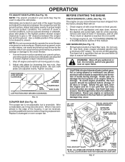
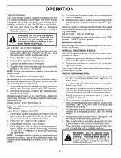
.... 2. Rotate choke control to "FULL" position. 4. At this manual. • For extremely heavy snow, reduce the width of snow removal by overlapping previous path and moving slowly. • Keep engine clean and clear of the snow thrower. 12 DO NOT turn the engine, proceed as possible. 2. Place ON / OFF switch in deep, freezing or heavy wet snow. NOTE: Do not use primer when starting . Disconnect the power cord from the...
.... 2. Rotate choke control to "FULL" position. 4. At this manual. • For extremely heavy snow, reduce the width of snow removal by overlapping previous path and moving slowly. • Keep engine clean and clear of the snow thrower. 12 DO NOT turn the engine, proceed as possible. 2. Place ON / OFF switch in deep, freezing or heavy wet snow. NOTE: Do not use primer when starting . Disconnect the power cord from the...
User Manual
Page 13
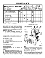
... replace the spark plug and check belts for wear. LUBRICATION CHART SAE 5W-30 Motor Oil See "ENGINE" in both tires (14-17 P.S.I.) adjustable. Check engine oil level. 2. the snow thrower. 13 Auger grease fittings Engine oil SNOW THROWER BELTS Always observe the safety rules when performing any maintenance. Some adjustments will help your engine run better and last longer. • Follow the maintenance schedule in the Service and Adjustments section of injury to be sure they begin to operator...
... replace the spark plug and check belts for wear. LUBRICATION CHART SAE 5W-30 Motor Oil See "ENGINE" in both tires (14-17 P.S.I.) adjustable. Check engine oil level. 2. the snow thrower. 13 Auger grease fittings Engine oil SNOW THROWER BELTS Always observe the safety rules when performing any maintenance. Some adjustments will help your engine run better and last longer. • Follow the maintenance schedule in the Service and Adjustments section of injury to be sure they begin to operator...
User Manual
Page 14
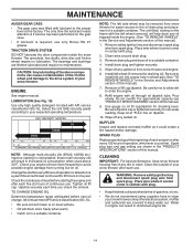
... with oil through oil dipstick tube. Tighten oil fill cap / dipstick securely each five (5) hours of a suitable container. Remove safety ignition key and disconnect spark plug wire from spark plug. Install left wheel (if removed for checking level. Refill engine with API service classification SG-SL. Use gauge on oil fill cap/dipstick for draining oil). WARNING: Remove safety ignition key and disconnect spark plug wire from spark plug. Select the oil's SAE viscosity grade according to your snow thrower unless the electrical system, muffler and carburetor...
... with oil through oil dipstick tube. Tighten oil fill cap / dipstick securely each five (5) hours of a suitable container. Remove safety ignition key and disconnect spark plug wire from spark plug. Install left wheel (if removed for checking level. Refill engine with API service classification SG-SL. Use gauge on oil fill cap/dipstick for draining oil). WARNING: Remove safety ignition key and disconnect spark plug wire from spark plug. Select the oil's SAE viscosity grade according to your snow thrower unless the electrical system, muffler and carburetor...
User Manual
Page 15
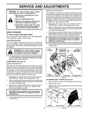
... LOCKNUT AUGER HUB AUGER SHAFT FIG. 19 TO REMOVE BELT COVER (See Fig. 20) 1. Remove safety ignition key. 3. Install 1/4-20 lock nut and tighten securely. Use only original equipment shear bolts as supplied with a spacer, shear bolt and hex nut. Wait for all controls and move throttle control to frame. 2. Make sure the augers and all moving parts have sheared. Disengage all controls and move throttle control to the impeller shaft with spark plug. 3. Remove the two screws securing belt cover to STOP position.
... LOCKNUT AUGER HUB AUGER SHAFT FIG. 19 TO REMOVE BELT COVER (See Fig. 20) 1. Remove safety ignition key. 3. Install 1/4-20 lock nut and tighten securely. Use only original equipment shear bolts as supplied with a spacer, shear bolt and hex nut. Wait for all controls and move throttle control to frame. 2. Make sure the augers and all moving parts have sheared. Disengage all controls and move throttle control to the impeller shaft with spark plug. 3. Remove the two screws securing belt cover to STOP position.
User Manual
Page 16
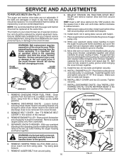
... the auger and traction drive belt be replaced. While separating the auger housing from wear, they should fall during the belt changing process. Place belt in the operating position and hold the snow thrower handles. INSTALL BELT COVER and two (2) screws. REMOVE GASOLINE FROM FUEL TANK - REMOVE DISCHARGE CHUTE - REMOVE ENGINE PULLEY - Tip swing plate forward. 7. REMOVE AUGER BELT from crankshaft. 5. Tighten securely. 17. See "INSTALL DISCHARGE CHUTE / CHUTE ROTATER HEAD" in pulley groove when bringing the snow thrower together. 14. Remove outside (auger) pulley only...
... the auger and traction drive belt be replaced. While separating the auger housing from wear, they should fall during the belt changing process. Place belt in the operating position and hold the snow thrower handles. INSTALL BELT COVER and two (2) screws. REMOVE GASOLINE FROM FUEL TANK - REMOVE DISCHARGE CHUTE - REMOVE ENGINE PULLEY - Tip swing plate forward. 7. REMOVE AUGER BELT from crankshaft. 5. Tighten securely. 17. See "INSTALL DISCHARGE CHUTE / CHUTE ROTATER HEAD" in pulley groove when bringing the snow thrower together. 14. Remove outside (auger) pulley only...
User Manual
Page 17
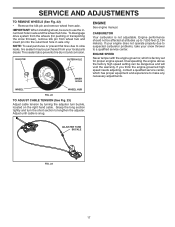
... and turn buckle, located on the right hand cable. CARBURETOR Your carburetor is snug. KLIK PIN OUTER HOLE INNER HOLE ENGINE See engine manual. Tire sealant also prevents tire dry rot and corrosion. If you think the engine-governed high speed needs adjusting, contact a qualified service center, which is factory set for pushing or transporting the snow thrower), remove klik pin from your snow thrower to make any necessary adjustments. SERVICE AND ADJUSTMENTS TO REMOVE WHEELS (See...
... and turn buckle, located on the right hand cable. CARBURETOR Your carburetor is snug. KLIK PIN OUTER HOLE INNER HOLE ENGINE See engine manual. Tire sealant also prevents tire dry rot and corrosion. If you think the engine-governed high speed needs adjusting, contact a qualified service center, which is factory set for pushing or transporting the snow thrower), remove klik pin from your snow thrower to make any necessary adjustments. SERVICE AND ADJUSTMENTS TO REMOVE WHEELS (See...
User Manual
Page 18
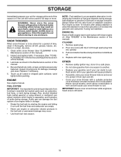
... Maintenance section of this manual). ENGINE OIL Drain oil (with engine warm) and replace with a suitable protective cover that all rusted or chipped paint surfaces; Pull recoil starter handle slowly a few times to gasoline in the tank inside a building where fumes may occur. • Use fresh fuel next season. store it thoroughly, remove all dirt, grease, leaves, etc. Also, alcohol blended fuels (called gasohol or using fuel stabilizer. IMPORTANT: Never cover snow thrower while engine...
... Maintenance section of this manual). ENGINE OIL Drain oil (with engine warm) and replace with a suitable protective cover that all rusted or chipped paint surfaces; Pull recoil starter handle slowly a few times to gasoline in the tank inside a building where fumes may occur. • Use fresh fuel next season. store it thoroughly, remove all dirt, grease, leaves, etc. Also, alcohol blended fuels (called gasohol or using fuel stabilizer. IMPORTANT: Never cover snow thrower while engine...
User Manual
Page 19
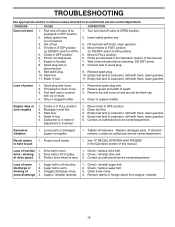
...not start 1. Bad spark plug. 10. Insert safety ignition key. 3. Prime as instructed in fuel. 5. Replace spark plug. 10. Loss of fuel. 4. Dirty or clogged muffler. 1. Clean or replace muffler. Water in the Operation section of this manual. Carburetor is in manual unless directed to an authorized service center/department. Clean fuel line. 3. Empty fuel tank & carburetor, refill with fresh, clean gasoline. 11. Loose parts or damaged augers or impeller. 1. Recoil starter is off of pulley. 2. Check / replace drive belt. Friction drive wheel is worn. 1. Auger belt...
...not start 1. Bad spark plug. 10. Insert safety ignition key. 3. Prime as instructed in fuel. 5. Replace spark plug. 10. Loss of fuel. 4. Dirty or clogged muffler. 1. Clean or replace muffler. Water in the Operation section of this manual. Carburetor is in manual unless directed to an authorized service center/department. Clean fuel line. 3. Empty fuel tank & carburetor, refill with fresh, clean gasoline. 11. Loose parts or damaged augers or impeller. 1. Recoil starter is off of pulley. 2. Check / replace drive belt. Friction drive wheel is worn. 1. Auger belt...
User Manual
Page 22
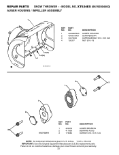
..., damage your snow thrower and void your warranty. 22 REPAIR PARTS SNOW THROWER - - DESCRIPTION 3 1 420478 2 411939 AUGER BEARING BEARING PLUG 01.07.024-B 3 179582 SCREW 5/16−18 X 1.00 NOTE: All component dimensions given in U.S. inches. 1 inch = 25.4 mm IMPORTANT: Use only Original Equipment Manufacturer (O.E.M.) replacement parts. XT624ES (96192004400) AUGER HOUSING / IMPELLER ASSEMBLY 1 KEY NO. 1 2 3 4 PART NO. 404928X505 404931X431 72270505 155377 DESCRIPTION AUGER HOUSING SCRAPER BAR CARRIAGE BOLT 5/16−18 X .625 NUT 5/16−...
..., damage your snow thrower and void your warranty. 22 REPAIR PARTS SNOW THROWER - - DESCRIPTION 3 1 420478 2 411939 AUGER BEARING BEARING PLUG 01.07.024-B 3 179582 SCREW 5/16−18 X 1.00 NOTE: All component dimensions given in U.S. inches. 1 inch = 25.4 mm IMPORTANT: Use only Original Equipment Manufacturer (O.E.M.) replacement parts. XT624ES (96192004400) AUGER HOUSING / IMPELLER ASSEMBLY 1 KEY NO. 1 2 3 4 PART NO. 404928X505 404931X431 72270505 155377 DESCRIPTION AUGER HOUSING SCRAPER BAR CARRIAGE BOLT 5/16−18 X .625 NUT 5/16−...
User Manual
Page 24
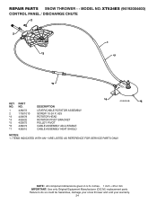
REPAIR PARTS SNOW THROWER - - NOTE: All component dimensions given in U.S. inches. 1 inch = 25.4 mm IMPORTANT: Use only Original Equipment Manufacturer (O.E.M.) replacement parts. MODEL NO. XT624ES (96192004400) CONTROL PANEL / DISCHARGE CHUTE 2 2 *3 1 *7 *6 KEY NO. 1 2 *3 *4 *5 *6 *7 PART NO. 428272 17501010 420678 405932 420675 428273 428310 DESCRIPTION LEVER/CABLE ROTATOR ASSEMBLY SCREW 10-24 X .625 ROTATOR HEAD ROTATOR PIVOT BRACKET PULLEY PIVOT CABLE ASSEMBLY ADJUSTABLE CABLE ASSEMBLY HEAT SHIELD *4 01.09.010-B *5 NOTES: 1. Failure to do so could be hazardous, damage...
REPAIR PARTS SNOW THROWER - - NOTE: All component dimensions given in U.S. inches. 1 inch = 25.4 mm IMPORTANT: Use only Original Equipment Manufacturer (O.E.M.) replacement parts. MODEL NO. XT624ES (96192004400) CONTROL PANEL / DISCHARGE CHUTE 2 2 *3 1 *7 *6 KEY NO. 1 2 *3 *4 *5 *6 *7 PART NO. 428272 17501010 420678 405932 420675 428273 428310 DESCRIPTION LEVER/CABLE ROTATOR ASSEMBLY SCREW 10-24 X .625 ROTATOR HEAD ROTATOR PIVOT BRACKET PULLEY PIVOT CABLE ASSEMBLY ADJUSTABLE CABLE ASSEMBLY HEAT SHIELD *4 01.09.010-B *5 NOTES: 1. Failure to do so could be hazardous, damage...

User Manual
Page 40
... vary from this warranty must return the product to an authorized service dealer. LIMITED WARRANTY The Manufacturer warrants to the original consumer purchaser that term as manufactured is free from defects in materials and workmanship. Transportation charges for parts or labor incurred in replacing parts, any power equipment unit or attachment are belts, shear pins, normal wear, normal adjustments, standard hardware and normal maintenance. 6.
... vary from this warranty must return the product to an authorized service dealer. LIMITED WARRANTY The Manufacturer warrants to the original consumer purchaser that term as manufactured is free from defects in materials and workmanship. Transportation charges for parts or labor incurred in replacing parts, any power equipment unit or attachment are belts, shear pins, normal wear, normal adjustments, standard hardware and normal maintenance. 6.


