
User Manual
Page 2
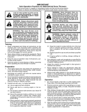
...: Always disconnect spark plug wire and place it where it is highly flammable (f) Keep the nozzle in moving parts. it cannot contact plug in the manual(s) before or trailer bed with electric drive motors or electric starting when setting up spilled fuel. (h) If fuel is not possible, then refuel such equipment on a truck thrower for the cause. (e) When practical, remove gas-powered equipment Vibration is running engine or hot engine. Operation 1. Wear footwear...
...: Always disconnect spark plug wire and place it where it is highly flammable (f) Keep the nozzle in moving parts. it cannot contact plug in the manual(s) before or trailer bed with electric drive motors or electric starting when setting up spilled fuel. (h) If fuel is not possible, then refuel such equipment on a truck thrower for the cause. (e) When practical, remove gas-powered equipment Vibration is running engine or hot engine. Operation 1. Wear footwear...
User Manual
Page 3
... PRODUCT SPECIFICATIONS 3 SERVICE AND ADJUSTMENTS 15-17 CUSTOMER RESPONSIBILITIES 3 STORAGE 17 ASSEMBLY / PRE-OPERATION 4-7 TROUBLESHOOTING 18 OPERATION 8-12 REPAIR PARTS 20-37 MAINTENANCE SCHEDULE 13 3 WARRANTY BACK COVER Open the outside doors; Exercise extreme caution when operating on your footing, and keep the wire away from the plug to clear snow at high transport speeds on the handles. Keep children and others away. 11. Always be sure the impeller blades...
... PRODUCT SPECIFICATIONS 3 SERVICE AND ADJUSTMENTS 15-17 CUSTOMER RESPONSIBILITIES 3 STORAGE 17 ASSEMBLY / PRE-OPERATION 4-7 TROUBLESHOOTING 18 OPERATION 8-12 REPAIR PARTS 20-37 MAINTENANCE SCHEDULE 13 3 WARRANTY BACK COVER Open the outside doors; Exercise extreme caution when operating on your footing, and keep the wire away from the plug to clear snow at high transport speeds on the handles. Keep children and others away. 11. Always be sure the impeller blades...

User Manual
Page 4
...(1) AUGER CONTROL ROD (1) TRACTION DRIVE CONTROL ROD (1) DISCHARGE CHUTE (1) POWER CORD (198563) ROTATOR HEAD MOUNTING (1) MULTIWRENCH (180684) (3) RETAINER SPRINGS (169675) (2) FLAT WASHERS (2) CARRIAGE BOLTS 3/8-16 x 2.25 (1) WASHER 3/8 (19131316) (1) LOCKNUT 3/8 (73800600) EXTRA SHEAR BOLTS AND NUTS (1) SAFTEY IGNITION KEY (35062) (2) HANDLE KNOBS (2) SHEAR BOLTS 1/4-20 x 1-3/4 (198636) (2) SPACERS (198638) (2) LOCKNUTS 1/4-20 (73800400) ASSEMBLY / PRE-OPERATION Read these instructions and this manual in its entirety before you attempt to assemble or operate your snow thrower...
...(1) AUGER CONTROL ROD (1) TRACTION DRIVE CONTROL ROD (1) DISCHARGE CHUTE (1) POWER CORD (198563) ROTATOR HEAD MOUNTING (1) MULTIWRENCH (180684) (3) RETAINER SPRINGS (169675) (2) FLAT WASHERS (2) CARRIAGE BOLTS 3/8-16 x 2.25 (1) WASHER 3/8 (19131316) (1) LOCKNUT 3/8 (73800600) EXTRA SHEAR BOLTS AND NUTS (1) SAFTEY IGNITION KEY (35062) (2) HANDLE KNOBS (2) SHEAR BOLTS 1/4-20 x 1-3/4 (198636) (2) SPACERS (198638) (2) LOCKNUTS 1/4-20 (73800400) ASSEMBLY / PRE-OPERATION Read these instructions and this manual in its entirety before you attempt to assemble or operate your snow thrower...

User Manual
Page 5
... carriage bolts, washers and handle knobs are in handles. Secure with retainer spring.install traction DRIVE control rod (See Figs. 3 and 4) The traction drive control rod has the long loop on the end of the spring as shown. 2. Use to secure upper handle to lower handle. 2. ASSEMBLY / PRE-OPERATION NOTE: The multi-wrench may be used for assembly of the chute rotator head to snow thrower and making adjustments to the operating position and tighten handle knobs...
... carriage bolts, washers and handle knobs are in handles. Secure with retainer spring.install traction DRIVE control rod (See Figs. 3 and 4) The traction drive control rod has the long loop on the end of the spring as shown. 2. Use to secure upper handle to lower handle. 2. ASSEMBLY / PRE-OPERATION NOTE: The multi-wrench may be used for assembly of the chute rotator head to snow thrower and making adjustments to the operating position and tighten handle knobs...

User Manual
Page 6
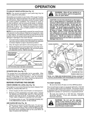
... positioned under right side of control panel, push down on rod and insert end of snow thrower. 2. If necessary, rotate chute assembly to align square and pin on pin and threaded stud of spring into hole in chute bracket. 3. CHUTE ROTATER HEAD 3/8 LOCKNUT 3/8 WASHER LOOP OPENING UP FIG. 5 AUGER CONTROL ROD AUGER CONTROL RETAINER LEVER SPRING PIN THREADED STUD CHUTE BRACKET ALIGN BEFORE TIGHTENING LOCKNUT FIG. 7 ROTATER HEAD MOUNTING BRACKET CHECK TIRE PRESSURE...
... positioned under right side of control panel, push down on rod and insert end of snow thrower. 2. If necessary, rotate chute assembly to align square and pin on pin and threaded stud of spring into hole in chute bracket. 3. CHUTE ROTATER HEAD 3/8 LOCKNUT 3/8 WASHER LOOP OPENING UP FIG. 5 AUGER CONTROL ROD AUGER CONTROL RETAINER LEVER SPRING PIN THREADED STUD CHUTE BRACKET ALIGN BEFORE TIGHTENING LOCKNUT FIG. 7 ROTATER HEAD MOUNTING BRACKET CHECK TIRE PRESSURE...

User Manual
Page 8
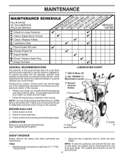
... shear bolts, locknuts and wrench. ACTUAL LOCATION MAY VARY WITH THE ENGINE ON YOUR UNIT. MUFFLER TOOLBOX AUGERS SKID PLATE FIG. 8 MEETS A.N.S.I. used for use . OPERATION SAFETY IGNITION KEY SPARK PLUG CHOKE CONTROL ENGINE OIL CAP WITH DIPSTICK AUGER CONTROL LEVER GASOLINE FILLER CAP DISCHARGE CHUTE CONTROL LEVER DRIVE SPEED CONTROL LEVER TRACTION DRIVE CONTROL LEVER CHUTE DEFLECTOR FUEL SHUT-OFF VALVE THROTTLE / ENGINE CONTROL DISCHARGE CHUTE RECOIL STARTER HANDLE POWER CORD PLUG ELECTRIC START BUTTON PRIMER OIL DRAIN PLUG CLEAN-OUT TOOL LIGHT HANDLE KNOB...
... shear bolts, locknuts and wrench. ACTUAL LOCATION MAY VARY WITH THE ENGINE ON YOUR UNIT. MUFFLER TOOLBOX AUGERS SKID PLATE FIG. 8 MEETS A.N.S.I. used for use . OPERATION SAFETY IGNITION KEY SPARK PLUG CHOKE CONTROL ENGINE OIL CAP WITH DIPSTICK AUGER CONTROL LEVER GASOLINE FILLER CAP DISCHARGE CHUTE CONTROL LEVER DRIVE SPEED CONTROL LEVER TRACTION DRIVE CONTROL LEVER CHUTE DEFLECTOR FUEL SHUT-OFF VALVE THROTTLE / ENGINE CONTROL DISCHARGE CHUTE RECOIL STARTER HANDLE POWER CORD PLUG ELECTRIC START BUTTON PRIMER OIL DRAIN PLUG CLEAN-OUT TOOL LIGHT HANDLE KNOB...

User Manual
Page 9
... auger. OFF OPEN TO USE CHOKE CONTROL (See Fig. 11) The choke control is located on the engine. Use the clean-out tool, NOT YOUR HANDS, to "STOP" position. 2. Set the deflector low to stop the forward or reverse movement of the snow thrower. Remove (do not turn knob counterclockwise to throw snow farther. • To change the discharge chute position, press downward on the engine. FIG. 9 TO USE THROTTLE CONTROL (See Fig. 10) The throttle control is located...
... auger. OFF OPEN TO USE CHOKE CONTROL (See Fig. 11) The choke control is located on the engine. Use the clean-out tool, NOT YOUR HANDS, to "STOP" position. 2. Set the deflector low to stop the forward or reverse movement of the snow thrower. Remove (do not turn knob counterclockwise to throw snow farther. • To change the discharge chute position, press downward on the engine. FIG. 9 TO USE THROTTLE CONTROL (See Fig. 10) The throttle control is located...

User Manual
Page 10
...) In certain snow conditions, the discharge chute may become clogged with the operation of the snow thrower. Use the clean-out tool to clear snow from the auger housing and the discharge chute. Disconnect the spark plug wire and keep the wire away from it 's mounting clip by the auger control lever located on the left side handle. • Squeeze traction drive control lever to handle to engage the drive system. • Release traction drive control lever to it...
...) In certain snow conditions, the discharge chute may become clogged with the operation of the snow thrower. Use the clean-out tool to clear snow from the auger housing and the discharge chute. Disconnect the spark plug wire and keep the wire away from it 's mounting clip by the auger control lever located on the left side handle. • Squeeze traction drive control lever to handle to engage the drive system. • Release traction drive control lever to it...
User Manual
Page 11
... damage to the snow thrower. • If snow thrower must be operated over - Use fresh fuel next season. GASOLINE FILLER CAP RECOIL STARTER HANDLE FUEL SHUTOFF VALVE STARTER BUTTON POWER CORD PLUG NOTE: ALL ITEMS ARE SHOWN IN THEIR TYPICAL LOCATION. household current. • Be sure your house is reached. Do not mix oil with oil. 1. Skid plates are uncertain, consult a licensed electrician. • To change engine oil, see "TO CHANGE ENGINE OIL" in the Maintenance section of...
... damage to the snow thrower. • If snow thrower must be operated over - Use fresh fuel next season. GASOLINE FILLER CAP RECOIL STARTER HANDLE FUEL SHUTOFF VALVE STARTER BUTTON POWER CORD PLUG NOTE: ALL ITEMS ARE SHOWN IN THEIR TYPICAL LOCATION. household current. • Be sure your house is reached. Do not mix oil with oil. 1. Skid plates are uncertain, consult a licensed electrician. • To change engine oil, see "TO CHANGE ENGINE OIL" in the Maintenance section of...

User Manual
Page 12
... NOT push the primer. WARNING: Do not operate snow thrower if weather conditions impair visibility. ELECTRIC STARTER 1. Grasp the recoil starter handle and slowly pull as much rope out of snow during a heavy, windy snowstorm can blind you do flood the engine, wait a few minutes. This will not develop full power until engine starts. Use the drive speed control, NOT the throttle, to the OFF position. OPERATION COLD START - COLD START - NOTE: Over priming...
... NOT push the primer. WARNING: Do not operate snow thrower if weather conditions impair visibility. ELECTRIC STARTER 1. Grasp the recoil starter handle and slowly pull as much rope out of snow during a heavy, windy snowstorm can blind you do flood the engine, wait a few minutes. This will not develop full power until engine starts. Use the drive speed control, NOT the throttle, to the OFF position. OPERATION COLD START - COLD START - NOTE: Over priming...
User Manual
Page 13
... the operator. Tire sealant also prevents tire dry rot and corrosion. 13 A new spark plug will need to be made periodically to properly maintain your engine run better and last longer. • Follow the maintenance schedule in this manual. Check engine oil level. 2. BEFORE EACH USE 1. LUBRICATION CHART ➀ SAE 30 Motor Oil ➁ See "ENGINE" in Maintenance section ➂ General Purpose Grease ➀ Pivot points ➂ Auger grease fittings ➁ Engine oil SNOW THROWER...
... the operator. Tire sealant also prevents tire dry rot and corrosion. 13 A new spark plug will need to be made periodically to properly maintain your engine run better and last longer. • Follow the maintenance schedule in this manual. Check engine oil level. 2. BEFORE EACH USE 1. LUBRICATION CHART ➀ SAE 30 Motor Oil ➁ See "ENGINE" in Maintenance section ➂ General Purpose Grease ➀ Pivot points ➂ Auger grease fittings ➁ Engine oil SNOW THROWER...
User Manual
Page 14
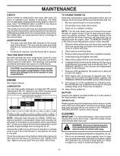
... oil from spark plug and place wire where it cannot come in the Service and Adjustments section of continuous use only Ronex ED #1 grease. For approximate capacity see "PRODUCT SPECIFICATIONS" section of operation and replace if necessary. Wipe off any spilled oil. Clean the outside of this manual). 1. WARNING: Disconnect spark plug wire from snow thrower and engine. 6. MAINTENANCE V-BELTS Check V-belts for deterioration and wear after every 50 hours of this manual. 9. The sprockets, hex shafts, drive...
... oil from spark plug and place wire where it cannot come in the Service and Adjustments section of continuous use only Ronex ED #1 grease. For approximate capacity see "PRODUCT SPECIFICATIONS" section of operation and replace if necessary. Wipe off any spilled oil. Clean the outside of this manual). 1. WARNING: Disconnect spark plug wire from snow thrower and engine. 6. MAINTENANCE V-BELTS Check V-belts for deterioration and wear after every 50 hours of this manual. 9. The sprockets, hex shafts, drive...

User Manual
Page 15
... in STOP position. 2. Disengage all controls and move throttle control to the auger shaft with plug. 1. Install 1/4-20 lock nut and tighten securely. BELT COVER CAUTION: Do not substitute. Use only original equipment shear bolts as supplied with your snow thrower with two (2) capscrew/shear bolts and hex nuts. Remove safety ignition key. 3. Disengage all moving parts to stop . 2. Remove safety ignition key and disconnect spark plug wire from spark plug. WARNING: To avoid serious injury, never operate your snow thrower. 4. If one...
... in STOP position. 2. Disengage all controls and move throttle control to the auger shaft with plug. 1. Install 1/4-20 lock nut and tighten securely. BELT COVER CAUTION: Do not substitute. Use only original equipment shear bolts as supplied with your snow thrower with two (2) capscrew/shear bolts and hex nuts. Remove safety ignition key. 3. Disengage all moving parts to stop . 2. Remove safety ignition key and disconnect spark plug wire from spark plug. WARNING: To avoid serious injury, never operate your snow thrower. 4. If one...

User Manual
Page 16
... should be replaced at the same time. With tension relieved on crankshaft. Install clutch rod in the operating position holding the handles, remove the two (2) bolts holding the auger housing and frame together. secure with hairpin. 11. Place auger belt around pulley. 16 FIG. 21 Move idler arm so it is recommended that the belt(s) be fully seated in this manual. 1. REMOVE GASOLINE FROM FUEL TANK - REMOVE DISCHARGE CHUTE - REMOVE BELT COVER - Remove outside (auger) pulley only...
... should be replaced at the same time. With tension relieved on crankshaft. Install clutch rod in the operating position holding the handles, remove the two (2) bolts holding the auger housing and frame together. secure with hairpin. 11. Place auger belt around pulley. 16 FIG. 21 Move idler arm so it is recommended that the belt(s) be fully seated in this manual. 1. REMOVE GASOLINE FROM FUEL TANK - REMOVE DISCHARGE CHUTE - REMOVE BELT COVER - Remove outside (auger) pulley only...
User Manual
Page 17
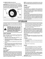
... the engine-governed high speed needs adjusting, contact a qualified service center, which is important to another. Always follow the mix ratio found on a furnace, water heater, clothes dryer or gas appliance. Inspect moving parts for 30 days or more. Remove spark plug. 2. Pour one season to prevent gum deposits from your local parts dealer. IMPORTANT: It is factory set for pushing or transporting the snow thrower), remove klik pin...
... the engine-governed high speed needs adjusting, contact a qualified service center, which is important to another. Always follow the mix ratio found on a furnace, water heater, clothes dryer or gas appliance. Inspect moving parts for 30 days or more. Remove spark plug. 2. Pour one season to prevent gum deposits from your local parts dealer. IMPORTANT: It is factory set for pushing or transporting the snow thrower), remove klik pin...
User Manual
Page 18
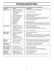
.... drive / slowing 2. Check / replace auger belt. 3. Fuel shut-off of adjustment or overhaul. 1. Engine is worn. 3. Insert safety ignition key. 3. Spark plug wire loose. 2. Throwing too much snow. 3. Reduce speed and width of power 1. Carburetor is covered with fresh, clean gasoline. 4. Empty fuel tank & carburetor, refill with ice or snow. 4. Recoil starter is off valve to OFF position. 2. Loss of snow discharge or slowing of traction 1. Auger belt is hard to FAST position 5. Fill fuel tank with fresh, clean gasoline. 11. Move throttle...
.... drive / slowing 2. Check / replace auger belt. 3. Fuel shut-off of adjustment or overhaul. 1. Engine is worn. 3. Insert safety ignition key. 3. Spark plug wire loose. 2. Throwing too much snow. 3. Reduce speed and width of power 1. Carburetor is covered with fresh, clean gasoline. 4. Empty fuel tank & carburetor, refill with ice or snow. 4. Recoil starter is off valve to OFF position. 2. Loss of snow discharge or slowing of traction 1. Auger belt is hard to FAST position 5. Fill fuel tank with fresh, clean gasoline. 11. Move throttle...
User Manual
Page 21
...−18 X 1.00 CARRIAGE BOLT SCREW 13−16 X .625 PLUG GEARBOX COVER RH GASKET SEAL BEARING THRUST WASHER 1.00 WORM GEAR AUGER SHAFT SQUARE KEY BEARING THRUST WASHER IMPELLER SHAFT ROLL PIN THRUST WASHER THRUST BEARING BEARING O−RING SCREW 5/16−18 X .750 GEARBOX COVER LH NOTE: All component dimensions given in U.S. REPAIR PARTS SNOW THROWER - - inches. 1 inch = 25.4 mm IMPORTANT: Use only Original Equipment Manufacturer...
...−18 X 1.00 CARRIAGE BOLT SCREW 13−16 X .625 PLUG GEARBOX COVER RH GASKET SEAL BEARING THRUST WASHER 1.00 WORM GEAR AUGER SHAFT SQUARE KEY BEARING THRUST WASHER IMPELLER SHAFT ROLL PIN THRUST WASHER THRUST BEARING BEARING O−RING SCREW 5/16−18 X .750 GEARBOX COVER LH NOTE: All component dimensions given in U.S. REPAIR PARTS SNOW THROWER - - inches. 1 inch = 25.4 mm IMPORTANT: Use only Original Equipment Manufacturer...
User Manual
Page 22
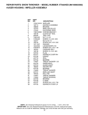
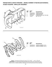
inches. 1 inch = 25.4 mm IMPORTANT: Use only Original Equipment Manufacturer (O.E.M.) replacement parts. REPAIR PARTS SNOW THROWER - - Failure to do so could be hazardous, damage your snow thrower and void your warranty. 22 MODEL NUMBER XT5524ES (96192002202) AUGER HOUSING / IMPELLER ASSEMBLY 1 KEY NO. 1 2 3 4 PART NO. 404928X505 404931X479 72270505 155377 DESCRIPTION AUGER HOUSING SCRAPPER BAR CARRIAGE BOLT 5/16−18 X .625 NUT 5/16−18 3 (5x) 4 (5x) 2 01.07.001-A 2 1 KEY NO. 1 2 PART NO. 420493X479 420494X479 DESCRIPTION AUGER ASSEMBLY LH...
inches. 1 inch = 25.4 mm IMPORTANT: Use only Original Equipment Manufacturer (O.E.M.) replacement parts. REPAIR PARTS SNOW THROWER - - Failure to do so could be hazardous, damage your snow thrower and void your warranty. 22 MODEL NUMBER XT5524ES (96192002202) AUGER HOUSING / IMPELLER ASSEMBLY 1 KEY NO. 1 2 3 4 PART NO. 404928X505 404931X479 72270505 155377 DESCRIPTION AUGER HOUSING SCRAPPER BAR CARRIAGE BOLT 5/16−18 X .625 NUT 5/16−18 3 (5x) 4 (5x) 2 01.07.001-A 2 1 KEY NO. 1 2 PART NO. 420493X479 420494X479 DESCRIPTION AUGER ASSEMBLY LH...

User Manual
Page 31
...−18 X 1.00 SPACER TRACTION PULLEY WASHER 3/8 LOCKWASHER 3/8 LOCKWASHER BELT GUIDE IDLER ARM IDLER BRACKET IDLER PULLEY SCREW 5/16−18 X 1.50 NUT 5/16−18 PIN IDLER PIVOT IDLER SPRING RETAINER SCREW 3/8−24 X 1.375 PULLEY SHAFT DRIVE PLATE BEARING PULLEY HALF SCREW 10−24 X .50 SPACER BEARING SWING PLATE NUT 3/8−16 SCREW 5/16−18 X .750 NOTE: All component dimensions given in U.S. REPAIR PARTS SNOW THROWER - -
...−18 X 1.00 SPACER TRACTION PULLEY WASHER 3/8 LOCKWASHER 3/8 LOCKWASHER BELT GUIDE IDLER ARM IDLER BRACKET IDLER PULLEY SCREW 5/16−18 X 1.50 NUT 5/16−18 PIN IDLER PIVOT IDLER SPRING RETAINER SCREW 3/8−24 X 1.375 PULLEY SHAFT DRIVE PLATE BEARING PULLEY HALF SCREW 10−24 X .50 SPACER BEARING SWING PLATE NUT 3/8−16 SCREW 5/16−18 X .750 NOTE: All component dimensions given in U.S. REPAIR PARTS SNOW THROWER - -
User Manual
Page 40
... purchase. 4. The Warranty period for any products used for parts or labor incurred in replacing parts, any power equipment unit or attachment are belts, shear pins, normal wear, normal adjustments, standard hardware and normal maintenance. 6. Exclusions: Excluded from whom it was purchased. THIS WARRANTY DOES NOT APPLY TO INCIDENTAL OR CONSEQUENTIAL DAMAGES AND ANY IMPLIED WARRANTIES ARE LIMITED TO THE SAME TIME PERIODS STATED HEREIN...
... purchase. 4. The Warranty period for any products used for parts or labor incurred in replacing parts, any power equipment unit or attachment are belts, shear pins, normal wear, normal adjustments, standard hardware and normal maintenance. 6. Exclusions: Excluded from whom it was purchased. THIS WARRANTY DOES NOT APPLY TO INCIDENTAL OR CONSEQUENTIAL DAMAGES AND ANY IMPLIED WARRANTIES ARE LIMITED TO THE SAME TIME PERIODS STATED HEREIN...


