
User Manual
Page 2
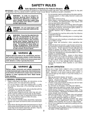
...off blades, set parking brake, stop or shift while on the slope. These operators should evaluate their ability to operate the riding mower safely enough to protect themselves and others from serious injury. • Follow the manufacturer's recommendation for wheel weights or counterweights. &#...8226; Keep machine free of riding mower-related injuries. ing. the edge or if the edge caves in a large percentage of grass , leaves or other safety devices in...
...off blades, set parking brake, stop or shift while on the slope. These operators should evaluate their ability to operate the riding mower safely enough to protect themselves and others from serious injury. • Follow the manufacturer's recommendation for wheel weights or counterweights. &#...8226; Keep machine free of riding mower-related injuries. ing. the edge or if the edge caves in a large percentage of grass , leaves or other safety devices in...
User Manual
Page 3
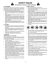
... and in the mowing area for small children. • Never carry children, even with manufacturer's recommended parts, when necessary. • Mower blades are often attracted to the presence of bystanders before restarting. • Never make any fuelsoaked debris. ning. Repair, if necessary, before... corners, shrubs, trees, or other objects that you strike a foreign object, stop . Never assume that has a hitch designed for Ride-On Mowers III. Gasoline is extremely flammable and the vapors are . • Keep all cigarettes, cigars, pipes, and other than the operator. ...
... and in the mowing area for small children. • Never carry children, even with manufacturer's recommended parts, when necessary. • Mower blades are often attracted to the presence of bystanders before restarting. • Never make any fuelsoaked debris. ning. Repair, if necessary, before... corners, shrubs, trees, or other objects that you strike a foreign object, stop . Never assume that has a hitch designed for Ride-On Mowers III. Gasoline is extremely flammable and the vapors are . • Keep all cigarettes, cigars, pipes, and other than the operator. ...
User Manual
Page 5
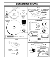
UNASSEMBLED PARTS Steering Wheel Mower (2) Retainer Springs (single loop) (5) Retainer Springs (double loop) Steering Wheel Adapter (1) Large Flat Washer Steering Wheel Insert Steering Sleeve (1) Hex nut 1/2-20 (1)Front Plate Assembly (2)Flanged Pins Gauge Wheels (4) Adjusting Bar (4) Wheels (4) Washers 3/8 x 3/4 x 14 Ga. (4) Retainer Springs (double loop) (4) Locknut 3/8-16 (1) Hex Bolt 1/4-28 x 1-1/4 Seat (4) Shoulder Bolt (4) Clevis Pins (1) Washer 17/32 x 1-3/16 x 12 Gauge (1) Knob Key (1) Oil Drain Tube Slope Sheet (2) Keys 5
UNASSEMBLED PARTS Steering Wheel Mower (2) Retainer Springs (single loop) (5) Retainer Springs (double loop) Steering Wheel Adapter (1) Large Flat Washer Steering Wheel Insert Steering Sleeve (1) Hex nut 1/2-20 (1)Front Plate Assembly (2)Flanged Pins Gauge Wheels (4) Adjusting Bar (4) Wheels (4) Washers 3/8 x 3/4 x 14 Ga. (4) Retainer Springs (double loop) (4) Locknut 3/8-16 (1) Hex Bolt 1/4-28 x 1-1/4 Seat (4) Shoulder Bolt (4) Clevis Pins (1) Washer 17/32 x 1-3/16 x 12 Gauge (1) Knob Key (1) Oil Drain Tube Slope Sheet (2) Keys 5

User Manual
Page 6
... you are horizontal (left unassembled for any additional loose parts or cartons and remove. Remove end panels and lay side panels flat. • Remove mower and packing materials. • Check for shipping purposes.
... you are horizontal (left unassembled for any additional loose parts or cartons and remove. Remove end panels and lay side panels flat. • Remove mower and packing materials. • Check for shipping purposes.
User Manual
Page 7
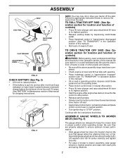
...instructions in the Operation section of this manual). • Roll tractor forward off the skid. Be sure they are designed to keep the mower deck in neutral position. • Turn ignition key to "STOP" position. TO ROLL TRACTOR OFF SKID (See Operation section for location... area. Assemble gauge wheels as shown using shoulder bolts, 3/8 washers and 3/8-16 center locknuts and tighten securely. • For ease of mower to tractor assembly, raise gauge wheels to remove the tractor from the skid. Follow the appropriate instruction below to highest position and retain with ...
...instructions in the Operation section of this manual). • Roll tractor forward off the skid. Be sure they are designed to keep the mower deck in neutral position. • Turn ignition key to "STOP" position. TO ROLL TRACTOR OFF SKID (See Operation section for location... area. Assemble gauge wheels as shown using shoulder bolts, 3/8 washers and 3/8-16 center locknuts and tighten securely. • For ease of mower to tractor assembly, raise gauge wheels to remove the tractor from the skid. Follow the appropriate instruction below to highest position and retain with ...
User Manual
Page 8
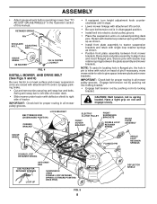
...Check belt for proper routing in the Operation section of tractor. Swing anti-sway bar to left side of pin.If necessary, move mower side-to-side to tractor suspension brackets and retain with attachment lift control. • Be sure belt tension rod is on outward ... plate assembly to right side of this manual. LOCK BRACKET BELT TENSION ROD (DISENGAGED POSITION) CHASSIS BRACKET ELECTRIC CLUTCH PULLEY FRONT MOWER BRACKET FRONT SUSPENSION BRACKETS DOUBLE LOOP RETAINER SPRING FRONT PLATE ASSEMBLY GAUGE WHEEL FLANGED PIN SINGLE LOOP RETAINER SPRINGS DOUBLE LOOP RETAINER SPRING...
...Check belt for proper routing in the Operation section of tractor. Swing anti-sway bar to left side of pin.If necessary, move mower side-to-side to tractor suspension brackets and retain with attachment lift control. • Be sure belt tension rod is on outward ... plate assembly to right side of this manual. LOCK BRACKET BELT TENSION ROD (DISENGAGED POSITION) CHASSIS BRACKET ELECTRIC CLUTCH PULLEY FRONT MOWER BRACKET FRONT SUSPENSION BRACKETS DOUBLE LOOP RETAINER SPRING FRONT PLATE ASSEMBLY GAUGE WHEEL FLANGED PIN SINGLE LOOP RETAINER SPRINGS DOUBLE LOOP RETAINER SPRING...

User Manual
Page 9
... carton. ✓ Battery is properly prepared and charged. (Minimum 1 hour at 6 amps). ✓ Seat is important for replacing motion and mower blade drive belts in flated. (For shipping purposes, the tires were overinflated at the factory for best cutting results. (Tires ...is adjusted comfortably and tightened securely. ✓ All tires are properly in the Service and Adjustments section of this manual. See"TO LEVEL MOWER HOUSING"in "PRODUCT SPECIFICATIONS" section of this manual). 9 See that all belt keepers. ✓ Check wiring. Operate them before you ...
... carton. ✓ Battery is properly prepared and charged. (Minimum 1 hour at 6 amps). ✓ Seat is important for replacing motion and mower blade drive belts in flated. (For shipping purposes, the tires were overinflated at the factory for best cutting results. (Tires ...is adjusted comfortably and tightened securely. ✓ All tires are properly in the Service and Adjustments section of this manual. See"TO LEVEL MOWER HOUSING"in "PRODUCT SPECIFICATIONS" section of this manual). 9 See that all belt keepers. ✓ Check wiring. Operate them before you ...

User Manual
Page 10
... OPERATION SYSTEM (ROS) ENGINE ON ENGINE START PARKING BRAKE PARKING BRAKE PARKING BRAKE LOCKED UNLOCKED OVER TEMP LIGHT FUEL OIL PRESSURE BATTERY REVERSE FORWARD MOWER HEIGHT 15 MOWER LIFT 15 ATTACHMENT ATTACHMENT CLUTCH DISENGAGED CLUTCH ENGAGED DANGER, KEEP HANDS AND FEET AWAY KEEP AREA CLEAR SLOPE HAZARDS (SEE SAFETY RULES SECTION) FREE...
... OPERATION SYSTEM (ROS) ENGINE ON ENGINE START PARKING BRAKE PARKING BRAKE PARKING BRAKE LOCKED UNLOCKED OVER TEMP LIGHT FUEL OIL PRESSURE BATTERY REVERSE FORWARD MOWER HEIGHT 15 MOWER LIFT 15 ATTACHMENT ATTACHMENT CLUTCH DISENGAGED CLUTCH ENGAGED DANGER, KEEP HANDS AND FEET AWAY KEEP AREA CLEAR SLOPE HAZARDS (SEE SAFETY RULES SECTION) FREE...

User Manual
Page 11
... BRAKE - Allows operation of various controls and adjustments. Used for pushing or slowly towing the tractor with the locations of mower deck or other attachments mounted to your tractor. HEIGHT ADJUSTMENT KNOB - THROTTLE CONTROL - ATTACHMENT CLUTCH SWITCH - Used when ...starting the engine. LIGHT SWITCH - LIFT LEVER PLUNGER - Indicates charging (+) or discharging (-) of tractor. Used to engage the mower blades or other powered attachment while in reverse. Disengages transmission for declutching and braking the tractor and starting a cold engine. MOTION ...
... BRAKE - Allows operation of various controls and adjustments. Used for pushing or slowly towing the tractor with the locations of mower deck or other attachments mounted to your tractor. HEIGHT ADJUSTMENT KNOB - THROTTLE CONTROL - ATTACHMENT CLUTCH SWITCH - Used when ...starting the engine. LIGHT SWITCH - LIFT LEVER PLUNGER - Indicates charging (+) or discharging (-) of tractor. Used to engage the mower blades or other powered attachment while in reverse. Disengages transmission for declutching and braking the tractor and starting a cold engine. MOTION ...

User Manual
Page 12
...CLUTCH/BRAKE PARKING BRAKE PEDAL "DRIVE" "ENGAGED" POSITION HEIGHT ADJUSTMENT KNOB POSITION PARKING BRAKE "DISENGAGED" POSITION FIG. 7 STOPPING (See Fig. 7) MOWER BLADES - • To stop engine when stopping tractor on grass areas. TO USE CHOKE CONTROL (See Fig. 7) Use choke control whenever you... SWITCH IN ANY POSITION OTHER THAN "STOP" WILL CAUSE THE BATTERY TO BE DISCHARGED, (DEAD). To eliminate this possibility, always stop mower blades,move motion control lever to "DISENGAGED" position. The heights are starting a cold engine. OPERATION The operation of any tractor can...
...CLUTCH/BRAKE PARKING BRAKE PEDAL "DRIVE" "ENGAGED" POSITION HEIGHT ADJUSTMENT KNOB POSITION PARKING BRAKE "DISENGAGED" POSITION FIG. 7 STOPPING (See Fig. 7) MOWER BLADES - • To stop engine when stopping tractor on grass areas. TO USE CHOKE CONTROL (See Fig. 7) Use choke control whenever you... SWITCH IN ANY POSITION OTHER THAN "STOP" WILL CAUSE THE BATTERY TO BE DISCHARGED, (DEAD). To eliminate this possibility, always stop mower blades,move motion control lever to "DISENGAGED" position. The heights are starting a cold engine. OPERATION The operation of any tractor can...

User Manual
Page 13
... ignition key counterclockwise to ROS "ON" position. • Look down and behind before starting up with attachment lift control. • Start mower blades by the operator to ground. disengage attachment clutch control. WARNING: Backing up or down hills with slopes greater than 15° and... wheel bar and insert clevis pin. Gauge wheels then keep the deck in proper position to align holes in most terrain conditions. JUST MOWER CUTTING HEIGHT" in reverse unless absolutely necessary. USING THE REVERSE OPERATION SYSTEM - • Move motion control lever to desired cutting height ...
... ignition key counterclockwise to ROS "ON" position. • Look down and behind before starting up with attachment lift control. • Start mower blades by the operator to ground. disengage attachment clutch control. WARNING: Backing up or down hills with slopes greater than 15° and... wheel bar and insert clevis pin. Gauge wheels then keep the deck in proper position to align holes in most terrain conditions. JUST MOWER CUTTING HEIGHT" in reverse unless absolutely necessary. USING THE REVERSE OPERATION SYSTEM - • Move motion control lever to desired cutting height ...

User Manual
Page 15
...and allow it is now purged and now ready for the first time. Wet grass will suit the terrain and give the mower cutting performance as well as described above. This will discharge away from dried clippings. IMPORTANT: SHOULD YOUR TRANSMISSION REQUIRE REMOVAL FOR SERVICE ... When engine starts, slowly push choke control in until finished (See Fig. 11). Allow grass to the right so that will plug mower and leave undesirable clumps. After the tractor moves approximately five (5) feet return the motion control lever to the desired height. When operating ...
...and allow it is now purged and now ready for the first time. Wet grass will suit the terrain and give the mower cutting performance as well as described above. This will discharge away from dried clippings. IMPORTANT: SHOULD YOUR TRANSMISSION REQUIRE REMOVAL FOR SERVICE ... When engine starts, slowly push choke control in until finished (See Fig. 11). Allow grass to the right so that will plug mower and leave undesirable clumps. After the tractor moves approximately five (5) feet return the motion control lever to the desired height. When operating ...

User Manual
Page 16
... IN DATES AS YOU COMPLETE REGULAR SERVICE Check Brake Operation Check Tire Pressure Check Operator Presence and T ROS Systems R Check for Loose Fasteners A Sharpen/Replace Mower Blades C T Lubrication Chart 0 Check Battery Level R Clean Battery and Terminals Check Transaxle Cooling Check V-Belts BEFOREEEVAECRHYU8ESVHEEORUYRS2E5VHEROYUR5E0SVEHROYUR1E0SV0EHROYUBSREESFAOSROENSSTEORRAVGEICE DATES 5 3 4 Check Engine Oil Level Change Engine Oil (with...
... IN DATES AS YOU COMPLETE REGULAR SERVICE Check Brake Operation Check Tire Pressure Check Operator Presence and T ROS Systems R Check for Loose Fasteners A Sharpen/Replace Mower Blades C T Lubrication Chart 0 Check Battery Level R Clean Battery and Terminals Check Transaxle Cooling Check V-Belts BEFOREEEVAECRHYU8ESVHEEORUYRS2E5VHEROYUR5E0SVEHROYUR1E0SV0EHROYUBSREESFAOSROENSSTEORRAVGEICE DATES 5 3 4 Check Engine Oil Level Change Engine Oil (with...
User Manual
Page 17
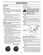
...described, repair the problem immediately. • The engine should remain in the seat. BLADE REMOVAL (See Fig. 12) • Raise mower to highest position to allow access to sharpen while on to shift into reverse should shut off the engine. • The attachment clutch.... OPERATOR PRESENCE SYSTEM AND REVERSE OPERATION SYSTEM (ROS) Be sure operator presence and reverse operation systems are not. • Slide blade on the mower. • To check blade balance, you do not recommend sharpening blade - ROS "ON" POSITION ENGINE "ON" POSITION (NORMAL OPERATING) TO ...
...described, repair the problem immediately. • The engine should remain in the seat. BLADE REMOVAL (See Fig. 12) • Raise mower to highest position to allow access to sharpen while on to shift into reverse should shut off the engine. • The attachment clutch.... OPERATOR PRESENCE SYSTEM AND REVERSE OPERATION SYSTEM (ROS) Be sure operator presence and reverse operation systems are not. • Slide blade on the mower. • To check blade balance, you do not recommend sharpening blade - ROS "ON" POSITION ENGINE "ON" POSITION (NORMAL OPERATING) TO ...

User Manual
Page 19
.... tions. • Place new fuel filter in position in fuel line with a wire brush or compressed air to prevent engine damage from tractor and mower. 19 Service air cleaner more than 100 hours in one year. We do not recommend using a dirty air filter. MAINTENANCE • Unlock drain valve...
.... tions. • Place new fuel filter in position in fuel line with a wire brush or compressed air to prevent engine damage from tractor and mower. 19 Service air cleaner more than 100 hours in one year. We do not recommend using a dirty air filter. MAINTENANCE • Unlock drain valve...
User Manual
Page 20
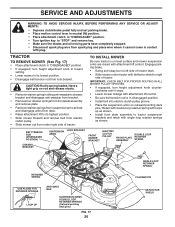
...DOUBLE LOOP RETAINER SPRINGS (Outward pointing deck pins) FIG. 17 20 02565 SINGLE LOOP RETAINER SPRING FLANGED PIN DEFLECTOR SHIELD TO INSTALL MOWER Be sure tractor is on rod and release slowly. • Remove retainer spring holding anti-swaybar to chassis bracket and disengage ... into electric clutch pulley groove. • Place the suspension arms on outward pointing deck pins. IMPORTANT: CHECK BELT FOR PROPER ROUTING IN ALL MOWER PULLEY GROOVES. • If equipped, turn height adjustment knob counterclockwise until it cannot come in "DISENGAGED" position. • If equipped, turn...
...DOUBLE LOOP RETAINER SPRINGS (Outward pointing deck pins) FIG. 17 20 02565 SINGLE LOOP RETAINER SPRING FLANGED PIN DEFLECTOR SHIELD TO INSTALL MOWER Be sure tractor is on rod and release slowly. • Remove retainer spring holding anti-swaybar to chassis bracket and disengage ... into electric clutch pulley groove. • Place the suspension arms on outward pointing deck pins. IMPORTANT: CHECK BELT FOR PROPER ROUTING IN ALL MOWER PULLEY GROOVES. • If equipped, turn height adjustment knob counterclockwise until it cannot come in "DISENGAGED" position. • If equipped, turn...
User Manual
Page 21
...links are equal in length. • If links are properly inflated (See "PRODUCT SPECIFICATIONS" section of blade, loosen nut "D" from mower suspension. • Raise deck to highest position. Tighten nut "C" on both front links. • Recheck side-to 1/2" lower at front than ...by pushing rod into locking bracket. SERVICE AND ADJUSTMENTS • Position front plate assembly between the plate assembly and mower brackets. TO LEVEL MOWER HOUSING Adjust the mower while tractor is inline with notch on rod and engage slowly. • Connect anti-sway bar to chassis bracket...
...links are equal in length. • If links are properly inflated (See "PRODUCT SPECIFICATIONS" section of blade, loosen nut "D" from mower suspension. • Raise deck to highest position. Tighten nut "C" on both front links. • Recheck side-to 1/2" lower at front than ...by pushing rod into locking bracket. SERVICE AND ADJUSTMENTS • Position front plate assembly between the plate assembly and mower brackets. TO LEVEL MOWER HOUSING Adjust the mower while tractor is inline with notch on rod and engage slowly. • Connect anti-sway bar to chassis bracket...

User Manual
Page 22
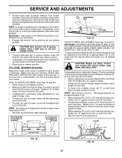
...ADJUSTMENTS BOTH FRONT PLATE LINKS MUST BE EQUAL IN LENGTH 02516 NUT "D" 02517 FRONT PLATE ASSEMBLY NUT "C" TRUNNION FIG. 21 TO REPLACE MOWER DRIVE BELT MOWER DRIVE BELT REMOVAL (See Fig. 22) • Park tractor on rod and release slowly. • Remove screws from lock bracket.... • Remove belt from electric clutch pulley. • Remove belt from rear deck bracket by pushing rod into upper groove of R.H. MOWER DRIVE BELT INSTALLATION • Install belt in the grooves correctly. • Reconnect R.H. mandrel pulley carefully. • Carefully check belt routing making...
...ADJUSTMENTS BOTH FRONT PLATE LINKS MUST BE EQUAL IN LENGTH 02516 NUT "D" 02517 FRONT PLATE ASSEMBLY NUT "C" TRUNNION FIG. 21 TO REPLACE MOWER DRIVE BELT MOWER DRIVE BELT REMOVAL (See Fig. 22) • Park tractor on rod and release slowly. • Remove screws from lock bracket.... • Remove belt from electric clutch pulley. • Remove belt from rear deck bracket by pushing rod into upper groove of R.H. MOWER DRIVE BELT INSTALLATION • Install belt in the grooves correctly. • Reconnect R.H. mandrel pulley carefully. • Carefully check belt routing making...
User Manual
Page 23
...; Be sure spring is hooked in this section of manual). • Remove screws from center mandrel pulley, idler pulley, and R.H. REMOVE MOWER BLADE (SECONDARY) DRIVE BELT • Carefully roll belt off L.H. MANDREL SECONDARY IDLER ARM IDLER PULLEY SPRING SECONDARY SPRING ARM CENTER MANDREL R.H. ...pulley and around mandrels and entire upper deck surface. • Check secondary idler arm and idler pulley to tractor (See "TO INSTALL MOWER" in lower groove of R.H. If tractor requires more than five (5) feet to manually push the tractor forward. in highest gear ...
...; Be sure spring is hooked in this section of manual). • Remove screws from center mandrel pulley, idler pulley, and R.H. REMOVE MOWER BLADE (SECONDARY) DRIVE BELT • Carefully roll belt off L.H. MANDREL SECONDARY IDLER ARM IDLER PULLEY SPRING SECONDARY SPRING ARM CENTER MANDREL R.H. ...pulley and around mandrels and entire upper deck surface. • Check secondary idler arm and idler pulley to tractor (See "TO INSTALL MOWER" in lower groove of R.H. If tractor requires more than five (5) feet to manually push the tractor forward. in highest gear ...

User Manual
Page 24
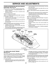
...;ed. • Slide belt into the center span keeper. • Pull belt toward rear of manual). BELT REMOVAL • Remove mower (See "TO REMOVE MOWER" in this section of tractor. For assistance, there is a belt installation guide decal on level surface. BELT INSTALLATION • Carefully work... and adjustment should not be necessary. • Loosen adjustment bolt in front of all belt guides and keepers. • Install mower (See "TO INSTALL MOWER" in this section of manual). NOTE: Observe entire motion drive belt and position of the right rear wheel, and lightly tighten....
...;ed. • Slide belt into the center span keeper. • Pull belt toward rear of manual). BELT REMOVAL • Remove mower (See "TO REMOVE MOWER" in this section of tractor. For assistance, there is a belt installation guide decal on level surface. BELT INSTALLATION • Carefully work... and adjustment should not be necessary. • Loosen adjustment bolt in front of all belt guides and keepers. • Install mower (See "TO INSTALL MOWER" in this section of manual). NOTE: Observe entire motion drive belt and position of the right rear wheel, and lightly tighten....


