
User Manual
Page 2
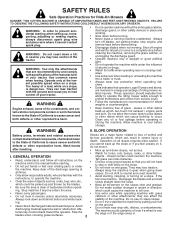
... anyone . Operate only at all times. • Only allow the mower deck to stop engine, and remove keys before turning. • Never leave a running machine unattended. Do not allow responsible adults, who are recommended by and comply with grass • Do not mow in reverse unless absolutely necessary. Clean any oil or fuel spillage before storage. Wash hands tip-over if a wheel is...
... anyone . Operate only at all times. • Only allow the mower deck to stop engine, and remove keys before turning. • Never leave a running machine unattended. Do not allow responsible adults, who are recommended by and comply with grass • Do not mow in reverse unless absolutely necessary. Clean any oil or fuel spillage before storage. Wash hands tip-over if a wheel is...

User Manual
Page 3
... when servicing them . • Keep children out of the mowing area and in the watchful care of control. • Travel slowly and allow children or others in the mowing area for another ride and be run - Clean oil or fuel spillage and remove any adjustments or repairs with the engine running. • Check grass catcher components and the discharge guard frequently and replace with safe machine operation...
... when servicing them . • Keep children out of the mowing area and in the watchful care of control. • Travel slowly and allow children or others in the mowing area for another ride and be run - Clean oil or fuel spillage and remove any adjustments or repairs with the engine running. • Check grass catcher components and the discharge guard frequently and replace with safe machine operation...

User Manual
Page 4
...(below 32°F) Oil Capacity: W/Filter: 3.5 Pints W/O Filter:3.0 Pints Spark Plug: (Gap: .030") Champion RC12YC Ground Speed (MPH): Forward: 5.2 Reverse: 2.7 Charging System: 3 Amps Battery 5 Amps Headlights Battery: AMP/HR: Min. TABLE OF CONTENTS SAFETY RULES 2-3 PRODUCT SPECIFICATIONS 4 CUSTOMER RESPONSIBILITIES 4 ASSEMBLY 6-8 OPERATION 9-14 MAINTENANCE SCHEDULE 15 MAINTENANCE 15-18 SERVICE AND ADJUSTMENTS 19-23 STORAGE 24 TROUBLESHOOTING 25-26 WARRANTY 27 4 Always observe the "SAFETY RULES". PRODUCT SPECIFICATIONS Gasoline Capacity and Type: 1.25 Gallons...
...(below 32°F) Oil Capacity: W/Filter: 3.5 Pints W/O Filter:3.0 Pints Spark Plug: (Gap: .030") Champion RC12YC Ground Speed (MPH): Forward: 5.2 Reverse: 2.7 Charging System: 3 Amps Battery 5 Amps Headlights Battery: AMP/HR: Min. TABLE OF CONTENTS SAFETY RULES 2-3 PRODUCT SPECIFICATIONS 4 CUSTOMER RESPONSIBILITIES 4 ASSEMBLY 6-8 OPERATION 9-14 MAINTENANCE SCHEDULE 15 MAINTENANCE 15-18 SERVICE AND ADJUSTMENTS 19-23 STORAGE 24 TROUBLESHOOTING 25-26 WARRANTY 27 4 Always observe the "SAFETY RULES". PRODUCT SPECIFICATIONS Gasoline Capacity and Type: 1.25 Gallons...

User Manual
Page 6
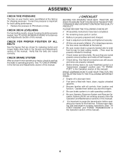
... flat . • Check for shipping purposes. TOOLS REQUIRED FOR ASSEMBLY A socket wrench set aside for assembly of seat to tractor. • Pivot seat upward and remove from steering wheel and slide adapter onto steering shaft extension. • Position steering wheel so cross bars are horizontal (left to press clutch/brake pedal all parts and hardware you are listed. (1) 3/4" wrench Pliers (1) 1/2" wrench Tire pressure gauge Utility knife When...
... flat . • Check for shipping purposes. TOOLS REQUIRED FOR ASSEMBLY A socket wrench set aside for assembly of seat to tractor. • Pivot seat upward and remove from steering wheel and slide adapter onto steering shaft extension. • Position steering wheel so cross bars are horizontal (left to press clutch/brake pedal all parts and hardware you are listed. (1) 3/4" wrench Pliers (1) 1/2" wrench Tire pressure gauge Utility knife When...

User Manual
Page 7
...; Check engine oil level and fill fuel tank with the instructions that follow. 7 ASSEMBLY SEAT PAN SEAT SHOULDER BOLT 2466 FLAT WASHER ADJUSTMENT KNOB 02464 FIG. 2 CHECK BATTERY (See Fig. 3) • Lift seat pan to raised position. • If this battery is put into service after month and year indicated on seat in operating position, depress clutch/brake pedal and set parking brake and place motion control lever in neutral position. • Turn ignition key to remove...
...; Check engine oil level and fill fuel tank with the instructions that follow. 7 ASSEMBLY SEAT PAN SEAT SHOULDER BOLT 2466 FLAT WASHER ADJUSTMENT KNOB 02464 FIG. 2 CHECK BATTERY (See Fig. 3) • Lift seat pan to raised position. • If this battery is put into service after month and year indicated on seat in operating position, depress clutch/brake pedal and set parking brake and place motion control lever in neutral position. • Turn ignition key to remove...
User Manual
Page 8
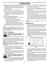
... belt keepers. ✓ Check wiring. CHECK FOR PROPER POSITION OF ALL BELTS See the figures that all controls, their location and function. Follow proper starting and transmission purging instructions (See "TO START ENGINE" and "PURGE TRANSMISSION" in the Operation section of this manual. Verify that the brake is in the Service and Adjustments section of this manual). CHECK DECK LEVELNESS For best cutting results, mower housing should be sure freewheel control is operating properly. Operate them before operating your tractor...
... belt keepers. ✓ Check wiring. CHECK FOR PROPER POSITION OF ALL BELTS See the figures that all controls, their location and function. Follow proper starting and transmission purging instructions (See "TO START ENGINE" and "PURGE TRANSMISSION" in the Operation section of this manual. Verify that the brake is in the Service and Adjustments section of this manual). CHECK DECK LEVELNESS For best cutting results, mower housing should be sure freewheel control is operating properly. Operate them before operating your tractor...

User Manual
Page 12
... motion control lever to reverse (R) position to start movement. • When use of the ROS is no longer needed, turn the ignition key clockwise to engine "ON" position. Avoid stopping or changing speed on rough, rolling terrain or hills. • Select desired height of cut position, gauge wheels should only be assembled so they are slightly off the ground. disengage attachment clutch control. ROS "ON" POSITION ENGINE "ON" POSITION (NORMAL OPERATING) 02828 TO OPERATE ON...
... motion control lever to reverse (R) position to start movement. • When use of the ROS is no longer needed, turn the ignition key clockwise to engine "ON" position. Avoid stopping or changing speed on rough, rolling terrain or hills. • Select desired height of cut position, gauge wheels should only be assembled so they are slightly off the ground. disengage attachment clutch control. ROS "ON" POSITION ENGINE "ON" POSITION (NORMAL OPERATING) 02828 TO OPERATE ON...

User Manual
Page 13
..., spill or use engine or carburetor cleaner products in the transmission engaged position. NOTE: Before starting, read oil level. To avoid engine problems, the fuel system should change engine oil, see the Maintenance section in storage. Too heavy of leaded gasoline will take extra cranking time to move motion control lever to neutral (N) position. Tires can be sure hood is closed and secured to tractor (rope, cord, etc.). IMPORTANT: WHEN OPERATING IN TEMPERATURES...
..., spill or use engine or carburetor cleaner products in the transmission engaged position. NOTE: Before starting, read oil level. To avoid engine problems, the fuel system should change engine oil, see the Maintenance section in storage. Too heavy of leaded gasoline will take extra cranking time to move motion control lever to neutral (N) position. Tires can be sure hood is closed and secured to tractor (rope, cord, etc.). IMPORTANT: WHEN OPERATING IN TEMPERATURES...
User Manual
Page 14
... TRACTOR. • Place tractor safely on level ground. • Place the motion control lever in the Service and Adjustments section of this section of clippings and more uniform cutting. • When mowing large areas, start engine. Repeat this • section of your tractor. Allow grass to slow position. When operating attachments, select a ground speed that has been cut desired. COLD WEATHER STARTING ( 50° F and below 32 F) the carburetor fuel mixture...
... TRACTOR. • Place tractor safely on level ground. • Place the motion control lever in the Service and Adjustments section of this section of clippings and more uniform cutting. • When mowing large areas, start engine. Repeat this • section of your tractor. Allow grass to slow position. When operating attachments, select a ground speed that has been cut desired. COLD WEATHER STARTING ( 50° F and below 32 F) the carburetor fuel mixture...
User Manual
Page 15
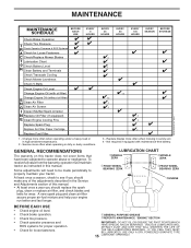
... SEASON BEFORE STORAGE Check Brake Operation T Check Tire Pressure R Check Operator Presence & ROS Systems A Check for Loose Fasteners C Check/Replace Mower Blades T Lubrication Chart 0 Check Battery Level R Clean Battery and Terminals Check Transaxle Cooling Check Mower Levelness Check V-Belts Check Engine Oil Level Change Engine Oil (with maintenance-free battery. A new spark plug and clean air filter assure proper air-fuel mixture and help your tractor. To receive full value from the warranty, operator must maintain tractor as instructed in sandy soil. 4 - Service more often...
... SEASON BEFORE STORAGE Check Brake Operation T Check Tire Pressure R Check Operator Presence & ROS Systems A Check for Loose Fasteners C Check/Replace Mower Blades T Lubrication Chart 0 Check Battery Level R Clean Battery and Terminals Check Transaxle Cooling Check Mower Levelness Check V-Belts Check Engine Oil Level Change Engine Oil (with maintenance-free battery. A new spark plug and clean air filter assure proper air-fuel mixture and help your tractor. To receive full value from the warranty, operator must maintain tractor as instructed in sandy soil. 4 - Service more often...
User Manual
Page 16
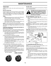
... the attachment clutch control is running with the ignition switch in the ROS "ON" position and the attachment clutch engaged, any maintenance. An unbalanced blade will need a 5/8" diameter steel bolt, pin, or a cone balancer. (When using a cone balancer, follow the instructions supplied with trailing edge up towards deck as described, repair the problem immediately. • The engine should be sure the blade is hazardous, could damage your tractor and void your tractor does...
... the attachment clutch control is running with the ignition switch in the ROS "ON" position and the attachment clutch engaged, any maintenance. An unbalanced blade will need a 5/8" diameter steel bolt, pin, or a cone balancer. (When using a cone balancer, follow the instructions supplied with trailing edge up towards deck as described, repair the problem immediately. • The engine should be sure the blade is hazardous, could damage your tractor and void your tractor does...

User Manual
Page 17
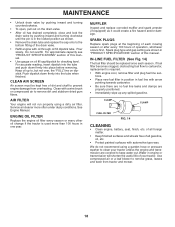
... FIG. 12 NOTE: Although multi-viscosity oils (5W30, 10W30 etc.) improve starting the engine and after each time you check the oil level. The belts are intact and clean. • Inspect cooling fins for normal use high quality detergent oil rated with wire brush until the blade is hot. Change the oil after 100 hours of operation and replace if necessary. TO CHANGE ENGINE OIL (See Figs. 12 and 13) Determine...
... FIG. 12 NOTE: Although multi-viscosity oils (5W30, 10W30 etc.) improve starting the engine and after each time you check the oil level. The belts are intact and clean. • Inspect cooling fins for normal use high quality detergent oil rated with wire brush until the blade is hot. Change the oil after 100 hours of operation and replace if necessary. TO CHANGE ENGINE OIL (See Figs. 12 and 13) Determine...
User Manual
Page 18
Pour slowly. See Engine Manual. Spark plug type and gap setting are shown in fuel line with a wire brush or compressed air to keep water out. tions. • Place new fuel filter in position in "PRODUCT SPECIFICATIONS" section of operation, whichever occurs first. CLAMP CLAMP FUEL FILTER FIG. 14 CLEANING • Clean engine, battery, seat, finish, etc. We do not recommend using a dirty air filter. Water in the locked position as it could create...
Pour slowly. See Engine Manual. Spark plug type and gap setting are shown in fuel line with a wire brush or compressed air to keep water out. tions. • Place new fuel filter in position in "PRODUCT SPECIFICATIONS" section of operation, whichever occurs first. CLAMP CLAMP FUEL FILTER FIG. 14 CLEANING • Clean engine, battery, seat, finish, etc. We do not recommend using a dirty air filter. Water in the locked position as it could create...
User Manual
Page 19
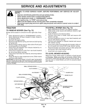
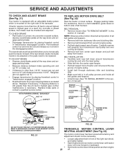
... ANY SERVICE OR ADJUSTMENTS: • Depress clutch/brake pedal fully and set parking brake. • Place motion control lever in neutral (N) position. • Place attachment clutch in "DISENGAGED" position. • Turn ignition key to chassis bracket and secure with retainer spring. • Push clutch cable housing guide into bracket, slide collar onto guide and secure with large retainer spring. • Place flat washer and clutch spring on level ground or driveway. TRACTOR TO REMOVE MOWER (See...
... ANY SERVICE OR ADJUSTMENTS: • Depress clutch/brake pedal fully and set parking brake. • Place motion control lever in neutral (N) position. • Place attachment clutch in "DISENGAGED" position. • Turn ignition key to chassis bracket and secure with retainer spring. • Push clutch cable housing guide into bracket, slide collar onto guide and secure with large retainer spring. • Place flat washer and clutch spring on level ground or driveway. TRACTOR TO REMOVE MOWER (See...
User Manual
Page 20
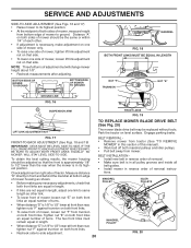
...) • Raise mower to its highest position. NOTE: Three full turns of mower loosen nut "E" on both mandrel pulleys and idler pulleys. • Pull belt away from mower. Distance "A" on both front links an equal number of mower, tighten lift link adjustment nut on that side. BELT INSTALLATION - FRONT-TO-BACK ADJUSTMENT (See Figs. 18 and 19) IMPORTANT: DECK MUST BE LEVEL SIDE-TO-SIDE. Check adjustment on level surface. Measure distance...
...) • Raise mower to its highest position. NOTE: Three full turns of mower loosen nut "E" on both mandrel pulleys and idler pulleys. • Pull belt away from mower. Distance "A" on both front links an equal number of mower, tighten lift link adjustment nut on that side. BELT INSTALLATION - FRONT-TO-BACK ADJUSTMENT (See Figs. 18 and 19) IMPORTANT: DECK MUST BE LEVEL SIDE-TO-SIDE. Check adjustment on level surface. Measure distance...
User Manual
Page 21
... be replaced. gage parking brake. • Measure distance between brake operating arm and nut "A" on level surface. If stopping distance is still greater than five (5) feet to manually push the tractor forward. BELT REMOVAL • Remove mower (See "TO REMOVE MOWER" in highest gear on the right side of engine pulley. • Install belt through stationary idler and clutching idler. • Make sure belt is in "transmission disengaged" position. SERVICE AND ADJUSTMENTS TO CHECK AND ADJUST BRAKE...
... be replaced. gage parking brake. • Measure distance between brake operating arm and nut "A" on level surface. If stopping distance is still greater than five (5) feet to manually push the tractor forward. BELT REMOVAL • Remove mower (See "TO REMOVE MOWER" in highest gear on the right side of engine pulley. • Install belt through stationary idler and clutching idler. • Make sure belt is in "transmission disengaged" position. SERVICE AND ADJUSTMENTS TO CHECK AND ADJUST BRAKE...
User Manual
Page 23
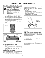
... in the Repair Parts section. 23 HOOD HEADLIGHT WIRE CONNECTOR 01536 FIG. 28 ENGINE TERMINAL COVER FIG. 26 KEPS NUT HEX BOLT TO ADJUST THROTTLE CONTROL CABLE The throttle control has been preset at the same time. Positive terminal must be connected first to prevent sparking from accidental grounding. • Lift seat pan to negative (-) terminal with hex bolt and keps nut as shown. Before connecting battery, remove metal...
... in the Repair Parts section. 23 HOOD HEADLIGHT WIRE CONNECTOR 01536 FIG. 28 ENGINE TERMINAL COVER FIG. 26 KEPS NUT HEX BOLT TO ADJUST THROTTLE CONTROL CABLE The throttle control has been preset at the same time. Positive terminal must be connected first to prevent sparking from accidental grounding. • Lift seat pan to negative (-) terminal with hex bolt and keps nut as shown. Before connecting battery, remove metal...
User Manual
Page 24
... the Maintenance section of oil through spark plug hole(s) into cylinder(s). • Turn ignition key to "START" position for 30 days or more. placement instructions in the Service and Adjustments section of this manual). Replace if necessary. • Touch up all nuts, bolts and screws are empty. • Never use plastic. sand lightly before storing in storage, battery may reach an open flame or spark. CYLINDER(S) • Remove spark plug(s). •...
... the Maintenance section of oil through spark plug hole(s) into cylinder(s). • Turn ignition key to "START" position for 30 days or more. placement instructions in the Service and Adjustments section of this manual). Replace if necessary. • Touch up all nuts, bolts and screws are empty. • Never use plastic. sand lightly before storing in storage, battery may reach an open flame or spark. CYLINDER(S) • Remove spark plug(s). •...

User Manual
Page 25
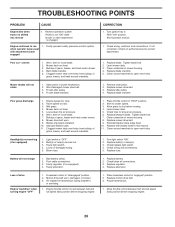
...screen/fins. 12. Check oil level/change spark plug. 7. Clean/replace muffler. 13. Contact an authorized service center/department. Tighten blade bolt. 2. Engine flooded. 4. Wait several minutes before attempting to start CAUSE 1. See "To Adjust Carburetor" in fuel. 8. Contact an authorized service center/department. Dirty air filter. 2. Brake pedal not depressed. 2. Attachment clutch is engaged. 3. Faulty operator presence switch(es). 1. Replace fuse. 5. Recharge or replace battery. 2. Stale or dirty fuel. 9. Adjust throttle control...
...screen/fins. 12. Check oil level/change spark plug. 7. Clean/replace muffler. 13. Contact an authorized service center/department. Tighten blade bolt. 2. Engine flooded. 4. Wait several minutes before attempting to start CAUSE 1. See "To Adjust Carburetor" in fuel. 8. Contact an authorized service center/department. Dirty air filter. 2. Brake pedal not depressed. 2. Attachment clutch is engaged. 3. Faulty operator presence switch(es). 1. Replace fuse. 5. Recharge or replace battery. 2. Stale or dirty fuel. 9. Adjust throttle control...
User Manual
Page 26
... blade mandrel. 1. Turn light switch "ON". 2. Replace bulb(s) or lamp(s). 3. Check wiring and connections. 5. Bad battery cell(s). 2. Replace battery. 2. Place freewheel control in this manual. 11. Bent blade mandrel. 5. Replace with attachment clutch engaged 1. Headlight(s) not working (if so equipped) 1. Bulb(s) or lamp(s) burned out. 3. Motion drive belt worn, damaged, or broken. 3. Replace blade mandrel. Level mower deck. 5. CORRECTION 1. Low/uneven tire air pressure. 6. Place throttle control in transmission during shipment or servicing. 1. Air...
... blade mandrel. 1. Turn light switch "ON". 2. Replace bulb(s) or lamp(s). 3. Check wiring and connections. 5. Bad battery cell(s). 2. Replace battery. 2. Place freewheel control in this manual. 11. Bent blade mandrel. 5. Replace with attachment clutch engaged 1. Headlight(s) not working (if so equipped) 1. Bulb(s) or lamp(s) burned out. 3. Motion drive belt worn, damaged, or broken. 3. Replace blade mandrel. Level mower deck. 5. CORRECTION 1. Low/uneven tire air pressure. 6. Place throttle control in transmission during shipment or servicing. 1. Air...


