
User Manual
Page 2
... protective devices in safe working condition. • Check shear pins, engine mounting bolts, and other bolts at high speeds on slippery surfaces. • Handle fuel with the controls and the proper use care when backing. • Never allow children to the State of the tiller. • Never operate the tiller without proper guards, plates, or other reproductive harm. 2 OPERATION • Do not put hands or feet near...
... protective devices in safe working condition. • Check shear pins, engine mounting bolts, and other bolts at high speeds on slippery surfaces. • Handle fuel with the controls and the proper use care when backing. • Never allow children to the State of the tiller. • Never operate the tiller without proper guards, plates, or other reproductive harm. 2 OPERATION • Do not put hands or feet near...
User Manual
Page 3
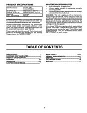
... states may have competent, well-trained technicians and the proper tools to assemble and maintain your purchase of this Owner's Manual. TABLE OF CONTENTS SAFETY RULES 2 CUSTOMER RESPONSIBILITIES 3 PRODUCT SPECIFICATIONS 3 ASSEMBLY 4-6 OPERATION 7-10 MAINTENANCE SCHEDULE 11 MAINTENANCE 11-13 SERVICE & ADJUSTMENTS 14-17 STORAGE 18 TROUBLESHOOTING 19 WARRANTY 21 3 The instructions will enable you the best possible dependability and performance. WARNING: This unit is...
... states may have competent, well-trained technicians and the proper tools to assemble and maintain your purchase of this Owner's Manual. TABLE OF CONTENTS SAFETY RULES 2 CUSTOMER RESPONSIBILITIES 3 PRODUCT SPECIFICATIONS 3 ASSEMBLY 4-6 OPERATION 7-10 MAINTENANCE SCHEDULE 11 MAINTENANCE 11-13 SERVICE & ADJUSTMENTS 14-17 STORAGE 18 TROUBLESHOOTING 19 WARRANTY 21 3 The instructions will enable you the best possible dependability and performance. WARNING: This unit is...
User Manual
Page 4
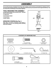
... x 1 x 11 Gauge (1) Handle Lock Lever (1) Hairpin Clip (1) Pivot Bolt 3/8-16 UNC Grade 5 Extra Shear Pins & Clips 4 TOOLS REQUIRED FOR ASSEMBLY A socket wrench set will make assembly easier. Standard wrench sizes are listed. (1) Utility knife (1) Tire pressure gauge (1) Pair of pliers (1) 9/16" wrench FRONT LEFT RIGHT OPERATOR'S POSITION (See Fig. 1) When right or left unassembled for shipping purposes. To ensure safe and proper operation of your tiller all parts and hardware...
... x 1 x 11 Gauge (1) Handle Lock Lever (1) Hairpin Clip (1) Pivot Bolt 3/8-16 UNC Grade 5 Extra Shear Pins & Clips 4 TOOLS REQUIRED FOR ASSEMBLY A socket wrench set will make assembly easier. Standard wrench sizes are listed. (1) Utility knife (1) Tire pressure gauge (1) Pair of pliers (1) 9/16" wrench FRONT LEFT RIGHT OPERATOR'S POSITION (See Fig. 1) When right or left unassembled for shipping purposes. To ensure safe and proper operation of your tiller all parts and hardware...

User Manual
Page 5
... easier adjustment. • Place flat washer on smooth side of carton and lay panels flat. • Lower the handle assembly. SIDE OF TILLER HANDLE ASSEMBLY GEARCASE NOTCH HANDLE LOCK • Grasp handle assembly. Tighten nut on L.H. Be sure handle lock remains in front part of plate and tighten. • Cut down remaining corners of handle lock to top frame and depth stake. Slide handle assembly into position.) VIEWED FROM R.H. Screw in handle lock lever...
... easier adjustment. • Place flat washer on smooth side of carton and lay panels flat. • Lower the handle assembly. SIDE OF TILLER HANDLE ASSEMBLY GEARCASE NOTCH HANDLE LOCK • Grasp handle assembly. Tighten nut on L.H. Be sure handle lock remains in front part of plate and tighten. • Cut down remaining corners of handle lock to top frame and depth stake. Slide handle assembly into position.) VIEWED FROM R.H. Screw in handle lock lever...
User Manual
Page 6
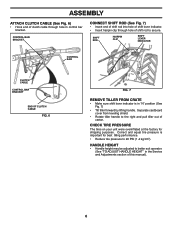
... SHIFT LEVER INDICATOR CONTROL BAR CLUTCH CABLE CONTROL BAR BRACKET END OF CLUTCH CABLE FIG. 6 FIG. 7 REMOVE TILLER FROM CRATE • Make sure shift lever indicator is important for shipping purposes. Separate cardboard cover from leveling shield. • Rotate tiller handle to better suit operator. (See "TO ADJUST HANDLE HEIGHT" in the Service and Adjustments section of this manual). 6 Correct and equal tire pressure is in control bar bracket. ASSEMBLY ATTACH CLUTCH CABLE (See Fig. 6) • Hook end of clutch cable...
... SHIFT LEVER INDICATOR CONTROL BAR CLUTCH CABLE CONTROL BAR BRACKET END OF CLUTCH CABLE FIG. 6 FIG. 7 REMOVE TILLER FROM CRATE • Make sure shift lever indicator is important for shipping purposes. Separate cardboard cover from leveling shield. • Rotate tiller handle to better suit operator. (See "TO ADJUST HANDLE HEIGHT" in the Service and Adjustments section of this manual). 6 Correct and equal tire pressure is in control bar bracket. ASSEMBLY ATTACH CLUTCH CABLE (See Fig. 6) • Hook end of clutch cable...

User Manual
Page 7
... . DRIVE CONTROL BAR - OUTER SIDE SHIELD - Used to start the engine. Shows which tiller will dig. Save this manual for future reference. These symbols may appear on your tiller to the safety standards of various controls and adjustments. Used to shift transmission gears. RECOIL STARTER HANDLE - THROTTLE CONTROL - LEVELING SHIELD - Adjustable to engage tines. OPERATION KNOW YOUR TILLER READ THIS OWNER'S MANUAL AND SAFETY RULES BEFORE OPERATING YOUR TILLER. Learn and understand their meaning. SHIFT LEVER INDICATOR - Used...
... . DRIVE CONTROL BAR - OUTER SIDE SHIELD - Used to start the engine. Shows which tiller will dig. Save this manual for future reference. These symbols may appear on your tiller to the safety standards of various controls and adjustments. Used to shift transmission gears. RECOIL STARTER HANDLE - THROTTLE CONTROL - LEVELING SHIELD - Adjustable to engage tines. OPERATION KNOW YOUR TILLER READ THIS OWNER'S MANUAL AND SAFETY RULES BEFORE OPERATING YOUR TILLER. Learn and understand their meaning. SHIFT LEVER INDICATOR - Used...

User Manual
Page 8
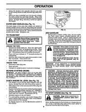
ENGINE • Move throttle control to "STOP" position. • Never use choke to shift gears. Pull the depth stake up for over spectacles or standard safety glasses. 00155 HOW TO USE YOUR TILLER Know how to operate all controls before adding fuel and oil or attempting to start engine. NUT "B" OUTER NUT "A" SIDE SHIELD depth_stake_1 "LOCKED" POSITION HARD TO SHIFT GEARS FIG. 11 • Briefly engage drive control bar and release or rock tiller forward and...
ENGINE • Move throttle control to "STOP" position. • Never use choke to shift gears. Pull the depth stake up for over spectacles or standard safety glasses. 00155 HOW TO USE YOUR TILLER Know how to operate all controls before adding fuel and oil or attempting to start engine. NUT "B" OUTER NUT "A" SIDE SHIELD depth_stake_1 "LOCKED" POSITION HARD TO SHIFT GEARS FIG. 11 • Briefly engage drive control bar and release or rock tiller forward and...
User Manual
Page 9
... separation and formation of depth stake to lock in position. OIL LEVEL FIG. 12 ADD GASOLINE • Fill fuel tank to bottom of this manual. USE CLEAN OIL AND FUEL AND STORE IN APPROVED, CLEAN, COVERED CONTAINERS. CHECK ENGINE OIL LEVEL (See Fig. 12) • The engine in your turn-around oil filler plug and remove plug. • Engine oil should be used within 1/2 inch of top of ignition until the fuel lines and carburetor are slotted so that the shields...
... separation and formation of depth stake to lock in position. OIL LEVEL FIG. 12 ADD GASOLINE • Fill fuel tank to bottom of this manual. USE CLEAN OIL AND FUEL AND STORE IN APPROVED, CLEAN, COVERED CONTAINERS. CHECK ENGINE OIL LEVEL (See Fig. 12) • The engine in your turn-around oil filler plug and remove plug. • Engine oil should be used within 1/2 inch of top of ignition until the fuel lines and carburetor are slotted so that the shields...
User Manual
Page 10
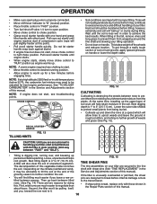
... starter handle with one hand and grasp tiller handle with those shown in cold temperatures (below 32°F), the carburetor fuel mixture may be adjusted for doing this vegetable matter enriches The tine assemblies on the climate (rainfall and wind), shaft with shear pins (See "TINE REPLACEMENT" in the it . 10 Then go back between passes. NOTE: If engine does not start , move choke control to half choke position. Pull rope...
... starter handle with one hand and grasp tiller handle with those shown in cold temperatures (below 32°F), the carburetor fuel mixture may be adjusted for doing this vegetable matter enriches The tine assemblies on the climate (rainfall and wind), shaft with shear pins (See "TINE REPLACEMENT" in the it . 10 Then go back between passes. NOTE: If engine does not start , move choke control to half choke position. Pull rope...

User Manual
Page 11
... manual should replace the spark plug, clean or replace air filter, and check tines and belts for loose fasteners. Some adjustments will need to be checked at least once each season. • Once a year you should be made periodically to operator abuse or negligence. BEFORE EACH USE • Check engine oil level. • Check tine operation. • Check for wear. All adjustments in high ambient temperatures. 2 - A new spark plug and clean air filter assure proper air-fuel mixture and help your tiller. LUBRICATION CHART c THROTTLE CONTROL d ENGINE...
... manual should replace the spark plug, clean or replace air filter, and check tines and belts for loose fasteners. Some adjustments will need to be checked at least once each season. • Once a year you should be made periodically to operator abuse or negligence. BEFORE EACH USE • Check engine oil level. • Check tine operation. • Check for wear. All adjustments in high ambient temperatures. 2 - A new spark plug and clean air filter assure proper air-fuel mixture and help your tiller. LUBRICATION CHART c THROTTLE CONTROL d ENGINE...
User Manual
Page 12
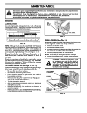
... spark plug wire before performing any maintenance (except carburetor adjustment) to prevent accidental starting of operation or at least once a year if the tiller is not used for maintenance. Change the oil after each time you check the oil level. Tighten oil filler plug securely each five (5) hours of the cartridge. For easier removal of grass, leaves, spilled oil, or fuel. Carefully remove air cleaner cartridge. NOTE: If very dirty or damaged, replace cartridge. 5. Keep the engine free...
... spark plug wire before performing any maintenance (except carburetor adjustment) to prevent accidental starting of operation or at least once a year if the tiller is not used for maintenance. Change the oil after each time you check the oil level. Tighten oil filler plug securely each five (5) hours of the cartridge. For easier removal of grass, leaves, spilled oil, or fuel. Carefully remove air cleaner cartridge. NOTE: If very dirty or damaged, replace cartridge. 5. Keep the engine free...
User Manual
Page 13
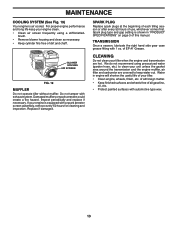
.... BLOWER HOUSING AIR SCREEN engine_art_71 FIG. 19 MUFFLER Do not operate tiller without muffler. Water in "PRODUCT SPECIFICATIONS" on page 3 of your tiller. • Clean engine, wheels, finish, etc. Inspect periodically and replace if necessary. CLEANING Do not clean your unit unless the gasket area around the transmission and the engine muffler, air filter and carburetor are covered to clean your tiller when the engine and transmission are hot. For proper engine performance and long life keep your engine clean...
.... BLOWER HOUSING AIR SCREEN engine_art_71 FIG. 19 MUFFLER Do not operate tiller without muffler. Water in "PRODUCT SPECIFICATIONS" on page 3 of your tiller. • Clean engine, wheels, finish, etc. Inspect periodically and replace if necessary. CLEANING Do not clean your unit unless the gasket area around the transmission and the engine muffler, air filter and carburetor are covered to clean your tiller when the engine and transmission are hot. For proper engine performance and long life keep your engine clean...
User Manual
Page 14
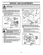
... of belt guard (located behind wheel). • Pull belt guard out and away from unit. • Replace belt guard by removing nuts "C" and "D". • Remove hairpin clip and clevis pin from wheel. • Remove wheel and tire. • Repair tire and reassemble. CLEVIS PIN NUT "C" NUT "D" HANDLE (LOW POSITION) HANDLE (HIGH POSITION) HANDLE LOCK LEVER TIRE CARE FIG. 20 CAUTION: When mounting tires, unless beads are not equal, tiller will be positioned at different settings between "HIGH" and "LOW" positions. • Retighten handle lock lever securely after adjusting...
... of belt guard (located behind wheel). • Pull belt guard out and away from unit. • Replace belt guard by removing nuts "C" and "D". • Remove hairpin clip and clevis pin from wheel. • Remove wheel and tire. • Repair tire and reassemble. CLEVIS PIN NUT "C" NUT "D" HANDLE (LOW POSITION) HANDLE (HIGH POSITION) HANDLE LOCK LEVER TIRE CARE FIG. 20 CAUTION: When mounting tires, unless beads are not equal, tiller will be positioned at different settings between "HIGH" and "LOW" positions. • Retighten handle lock lever securely after adjusting...

User Manual
Page 15
... REMOVE BELT GUARD". • Remove old belt by slipping off engine pulley first then remove from transmission pulley. • Place new belt in "ENGAGED" position. BELT MUST BE IN GROOVE ON TOP OF IDLER PULLEY. ENGINE PULLEY CABLE CLIP SCREW DRIVE CONTROL CABLE IDLER PULLEY TRANSMISSION PULLEY FIG. 23 LESS TENSION EXTENSION SPRING 5/8" MORE TENSION 15 This tension can be attained as described below. • Replace belt guard. • Reposition wheel and replace clevis pin and hairpin clip. NOTE POSITION OF BELT TO GUIDES. • Check belt adjustment...
... REMOVE BELT GUARD". • Remove old belt by slipping off engine pulley first then remove from transmission pulley. • Place new belt in "ENGAGED" position. BELT MUST BE IN GROOVE ON TOP OF IDLER PULLEY. ENGINE PULLEY CABLE CLIP SCREW DRIVE CONTROL CABLE IDLER PULLEY TRANSMISSION PULLEY FIG. 23 LESS TENSION EXTENSION SPRING 5/8" MORE TENSION 15 This tension can be attained as described below. • Replace belt guard. • Reposition wheel and replace clevis pin and hairpin clip. NOTE POSITION OF BELT TO GUIDES. • Check belt adjustment...

User Manual
Page 16
... be checked for sharpness, wear, and bending, particularly the tines which are sharp. A tine this worn needs to work harder and dig more shallow. If the gap between the tines exceeds 3-1/2 inches (9 cm), they should be replaced or straightened as necessary. • New tines should be assembled as good tines. Wear gloves or other protection when handling tines...
... be checked for sharpness, wear, and bending, particularly the tines which are sharp. A tine this worn needs to work harder and dig more shallow. If the gap between the tines exceeds 3-1/2 inches (9 cm), they should be replaced or straightened as necessary. • New tines should be assembled as good tines. Wear gloves or other protection when handling tines...
User Manual
Page 17
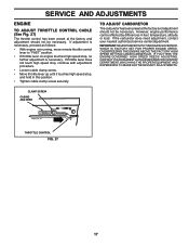
.... OVERSPEEDING THE ENGINE ABOVE THE FACTORY HIGH SPEED SETTING CAN BE DANGEROUS. If throttle lever does not touch high speed stop, continue with adjustment procedure. • Loosen cable clamp screw. • Move throttle lever up until it touches high speed stop , no further adjustment is necessary, proceed as follows: • With engine not running, move remote throttle control lever to "FAST" position. • If throttle lever on engine touches high speed stop , and hold in fuel, temperature, altitude...
.... OVERSPEEDING THE ENGINE ABOVE THE FACTORY HIGH SPEED SETTING CAN BE DANGEROUS. If throttle lever does not touch high speed stop, continue with adjustment procedure. • Loosen cable clamp screw. • Move throttle lever up until it touches high speed stop , no further adjustment is necessary, proceed as follows: • With engine not running, move remote throttle control lever to "FAST" position. • If throttle lever on engine touches high speed stop , and hold in fuel, temperature, altitude...
User Manual
Page 18
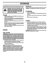
... fuel tank by starting the engine and let it to cool before painting. CYLINDER(S) • Remove spark plug. • Pour 1 ounce (29 ml) of this manual. • Be sure that does not retain moisture. Do not use engine or carburetor cleaner products in fuel tank or storage container. Rust and/or dirt in the Maintenance section of oil through spark plug hole into cylinder. • Pull starter handle slowly several times...
... fuel tank by starting the engine and let it to cool before painting. CYLINDER(S) • Remove spark plug. • Pour 1 ounce (29 ml) of this manual. • Be sure that does not retain moisture. Do not use engine or carburetor cleaner products in fuel tank or storage container. Rust and/or dirt in the Maintenance section of oil through spark plug hole into cylinder. • Pull starter handle slowly several times...
User Manual
Page 19
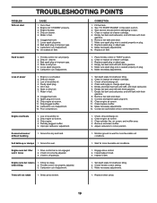
... level/dirty oil. 2. Improper carburetor adjustment. Drive control bar is off pulley(s). V-belt is not engaged. 2. See "TO START ENGINE" in "FAST" position. 2. Remove fuel tank and clean. 7. Empty and clean fuel tank and refill, and clean carburetor. 6. Remove fuel tank and clean. 9. Connect and tighten spark plug wire. 10. Clean/replace muffler. 12. Contact an authorized service center/department. 1. Inspect/adjust V-belt. 3. Check throttle control setting. 3. Dirty air cleaner. 5. Bad spark plug or improper gap. 9. Oil soaked air filter. Bad spark plug...
... level/dirty oil. 2. Improper carburetor adjustment. Drive control bar is off pulley(s). V-belt is not engaged. 2. See "TO START ENGINE" in "FAST" position. 2. Remove fuel tank and clean. 7. Empty and clean fuel tank and refill, and clean carburetor. 6. Remove fuel tank and clean. 9. Connect and tighten spark plug wire. 10. Clean/replace muffler. 12. Contact an authorized service center/department. 1. Inspect/adjust V-belt. 3. Check throttle control setting. 3. Dirty air cleaner. 5. Bad spark plug or improper gap. 9. Oil soaked air filter. Bad spark plug...
User Manual
Page 21
...Drive Mississauga, Ontario L5T 1K6 giving the model number, serial number and date of purchase of your product and the name and address of that this warranty must return the product to an authorized service dealer. Should you have other rights which we find to be paid by the original consumer purchaser, we will repair or replace... may have any power equipment unit or attachment are belts, tines, tine adapters, normal wear, normal adjustments, standard hardware and normal maintenance. 6. This warranty does not apply to the applicable manufacturer's warranty on these items....
...Drive Mississauga, Ontario L5T 1K6 giving the model number, serial number and date of purchase of your product and the name and address of that this warranty must return the product to an authorized service dealer. Should you have other rights which we find to be paid by the original consumer purchaser, we will repair or replace... may have any power equipment unit or attachment are belts, tines, tine adapters, normal wear, normal adjustments, standard hardware and normal maintenance. 6. This warranty does not apply to the applicable manufacturer's warranty on these items....
User Manual
Page 22
... updated information and assistance. If the operating characteristics or the appearance of part. The philosophy of Electrolux Home Products is to our website: www.poulan-pro.com/support.asp NOTE: Poulan Pro provides parts and service through its products. Model Number/Manufacturer's I.D. For Parts and service, contact our authorized distributor: call 1-800-829-5886 For a Parts Manual, go to continually improve all mechanical products, some adjustments or part replacement...
... updated information and assistance. If the operating characteristics or the appearance of part. The philosophy of Electrolux Home Products is to our website: www.poulan-pro.com/support.asp NOTE: Poulan Pro provides parts and service through its products. Model Number/Manufacturer's I.D. For Parts and service, contact our authorized distributor: call 1-800-829-5886 For a Parts Manual, go to continually improve all mechanical products, some adjustments or part replacement...


