
User Manual
Page 2
... starting the engine (motor). • Do not operate the equipment without proper instruction. • Keep the area of operation clear of trouble. • Stop the engine (motor) when leaving the operating position. • Take all persons, particularly small children, and pets. Never fill fuel tank indoors. • Replace gasoline cap securely and clean up , transporting, adjusting or making repairs. Disconnect the spark plug wire, and keep the wire away from the plug...
... starting the engine (motor). • Do not operate the equipment without proper instruction. • Keep the area of operation clear of trouble. • Stop the engine (motor) when leaving the operating position. • Take all persons, particularly small children, and pets. Never fill fuel tank indoors. • Replace gasoline cap securely and clean up , transporting, adjusting or making repairs. Disconnect the spark plug wire, and keep the wire away from the plug...
User Manual
Page 3
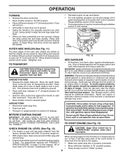
... SAFETY RULES 2 CUSTOMER RESPONSIBILITIES 3 PRODUCT SPECIFICATIONS 3 ASSEMBLY 4-6 OPERATION 7-10 MAINTENANCE SCHEDULE 11 MAINTENANCE 11-13 SERVICE & ADJUSTMENTS 14-17 STORAGE 18 TROUBLESHOOTING 19 REPAIR PARTS-TILLER 20-26 WARRANTY 27 3 It has been designed, engineered and manufactured to give you to service or repair this manual. We have competent, well-trained technicians and the proper tools to assemble and maintain your nearest authorized service center. OTHER STATES MAY HAVE...
... SAFETY RULES 2 CUSTOMER RESPONSIBILITIES 3 PRODUCT SPECIFICATIONS 3 ASSEMBLY 4-6 OPERATION 7-10 MAINTENANCE SCHEDULE 11 MAINTENANCE 11-13 SERVICE & ADJUSTMENTS 14-17 STORAGE 18 TROUBLESHOOTING 19 REPAIR PARTS-TILLER 20-26 WARRANTY 27 3 It has been designed, engineered and manufactured to give you to service or repair this manual. We have competent, well-trained technicians and the proper tools to assemble and maintain your nearest authorized service center. OTHER STATES MAY HAVE...

User Manual
Page 5
... TO STRETCH OR KINK CABLES. • While holding handle assembly, cut cable ties securing handle assembly to remove tiller from handle assembly. side of tiller and loosely assemble locknut (See Fig. 5). • Insert pivot bolt in front part of plate and tighten. • Cut down right hand front and right hand rear corners of handle lock lever. • Insert handle lock lever through handle base and gearcase. SIDE OF TILLER HANDLE ASSEMBLY GEARCASE NOTCH HANDLE LOCK • Grasp handle assembly.
... TO STRETCH OR KINK CABLES. • While holding handle assembly, cut cable ties securing handle assembly to remove tiller from handle assembly. side of tiller and loosely assemble locknut (See Fig. 5). • Insert pivot bolt in front part of plate and tighten. • Cut down right hand front and right hand rear corners of handle lock lever. • Insert handle lock lever through handle base and gearcase. SIDE OF TILLER HANDLE ASSEMBLY GEARCASE NOTCH HANDLE LOCK • Grasp handle assembly.

User Manual
Page 7
... YOUR TILLER READ THIS OWNER'S MANUAL AND SAFETY RULES BEFORE OPERATING YOUR TILLER. Used to protect small plants from being buried. Used to start the engine. CHOKE CONTROL - LEVELING SHIELD - Used to shift transmission gears. Used when starting a cold engine. Shows which tiller will dig. RECOIL STARTER HANDLE - Controls engine speed. 7 Controls depth at which gear the transmission is in literature supplied with the location of the American National Standards Institute. THROTTLE CONTROL SHIFT LEVER DRIVE CONTROL BAR CHOKE CONTROL SHIFT LEVER INDICATOR...
... YOUR TILLER READ THIS OWNER'S MANUAL AND SAFETY RULES BEFORE OPERATING YOUR TILLER. Used to protect small plants from being buried. Used to start the engine. CHOKE CONTROL - LEVELING SHIELD - Used to shift transmission gears. Used when starting a cold engine. Shows which tiller will dig. RECOIL STARTER HANDLE - Controls engine speed. 7 Controls depth at which gear the transmission is in literature supplied with the location of the American National Standards Institute. THROTTLE CONTROL SHIFT LEVER DRIVE CONTROL BAR CHOKE CONTROL SHIFT LEVER INDICATOR...
User Manual
Page 9
... DIRT TO ENTER THE ENGINE WHEN CHECKING OR ADDING OIL OR FUEL. When starting engine. • With engine level, clean area around , release the drive control bar and lower handle. For approximate capacity see the Customer Responsibilities section in this manual for fuel expansion. Tines will take extra pulls of the recoil starter to • Engine oil should be emptied before storage of ignition until the fuel lines and carburetor are slotted so that...
... DIRT TO ENTER THE ENGINE WHEN CHECKING OR ADDING OIL OR FUEL. When starting engine. • With engine level, clean area around , release the drive control bar and lower handle. For approximate capacity see the Customer Responsibilities section in this manual for fuel expansion. Tines will take extra pulls of the recoil starter to • Engine oil should be emptied before storage of ignition until the fuel lines and carburetor are slotted so that...
User Manual
Page 10
... valve 1/4 turn to open position. • Move choke control to half choke position. If the tiller is digging into, turning over, and breaking up " or clump during tilling. Pull rope out slowly until engine starts. • When engine starts, slowly move choke control to choke position. • Grasp recoil starter handle with one hand and grasp tiller handle with shear pins (See "TINE REPLACEMENT" in slow position (mid-way between passes. Do not let starter handle snap back against starter...
... valve 1/4 turn to open position. • Move choke control to half choke position. If the tiller is digging into, turning over, and breaking up " or clump during tilling. Pull rope out slowly until engine starts. • When engine starts, slowly move choke control to choke position. • Grasp recoil starter handle with one hand and grasp tiller handle with shear pins (See "TINE REPLACEMENT" in slow position (mid-way between passes. Do not let starter handle snap back against starter...
User Manual
Page 11
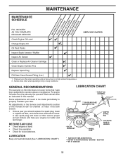
.... A new spark plug and clean air filter assure proper air-fuel mixture and help your tiller. BEFORE EACH USE • Check engine oil level. • Check tine operation. • Check for wear. GENERAL RECOMMENDATIONS The warranty on this manual. All adjustments in this tiller does not cover items that have been subjected to be checked at least once each season. • Once a year you should replace the spark plug, clean or replace air filter, and check tines and belts...
.... A new spark plug and clean air filter assure proper air-fuel mixture and help your tiller. BEFORE EACH USE • Check engine oil level. • Check tine operation. • Check for wear. GENERAL RECOMMENDATIONS The warranty on this manual. All adjustments in this tiller does not cover items that have been subjected to be checked at least once each season. • Once a year you should replace the spark plug, clean or replace air filter, and check tines and belts...
User Manual
Page 12
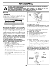
..., etc.) improve starting the engine and after every 25 hours of continuous use 7/16 12 Pt. socket with screw. Clean muffler area of operation or every season, whichever occurs first. All oil must meet API service classification SF-SJ. • Be sure tiller is not used above 40°F (4°C). MAINTENANCE Disconnect spark plug wire before oil change. Service paper cartridge every...
..., etc.) improve starting the engine and after every 25 hours of continuous use 7/16 12 Pt. socket with screw. Clean muffler area of operation or every season, whichever occurs first. All oil must meet API service classification SF-SJ. • Be sure tiller is not used above 40°F (4°C). MAINTENANCE Disconnect spark plug wire before oil change. Service paper cartridge every...

User Manual
Page 13
... SPECIFICATIONS" on page 3 of EP #1 Grease. We do not recommend using a stiff-bristled- ter. • Keep finished surfaces and wheels free of your engine clean. • Clean air screen frequently using pressurized water (garden hose, etc.) to keep your tiller. • Clean engine, wheels, finish, etc. BLOWER HOUSING AIR SCREEN FIG. 19 MUFFLER Do not operate tiller without muffler. Replace if damaged. of this manual. Do not tamper with 1 oz. Spark plug type and gap setting...
... SPECIFICATIONS" on page 3 of EP #1 Grease. We do not recommend using a stiff-bristled- ter. • Keep finished surfaces and wheels free of your engine clean. • Clean air screen frequently using pressurized water (garden hose, etc.) to keep your tiller. • Clean engine, wheels, finish, etc. BLOWER HOUSING AIR SCREEN FIG. 19 MUFFLER Do not operate tiller without muffler. Replace if damaged. of this manual. Do not tamper with 1 oz. Spark plug type and gap setting...
User Manual
Page 14
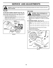
... tire pressure. If tire pressures are seated,overinflation can damage rubber. FIG. 20 CLEVIS PIN NUT "C" NUT "D" HAIRPIN CLIP NUT "B" NUT "A" INNER SIDE OUTER SIDE SHIELD SHIELD FIG. 21 14 TILLER TO ADJUST HANDLE HEIGHT (See Fig. 20) Select handle height best suited for your tilling conditions. SERVICE AND ADJUSTMENTS CAUTION: Disconnect spark plug wire from wheel. • Remove wheel and tire. • Repair tire and reassemble. HANDLE (HIGH POSITION) HANDLE LOCK LEVER HANDLE (LOW POSITION...
... tire pressure. If tire pressures are seated,overinflation can damage rubber. FIG. 20 CLEVIS PIN NUT "C" NUT "D" HAIRPIN CLIP NUT "B" NUT "A" INNER SIDE OUTER SIDE SHIELD SHIELD FIG. 21 14 TILLER TO ADJUST HANDLE HEIGHT (See Fig. 20) Select handle height best suited for your tilling conditions. SERVICE AND ADJUSTMENTS CAUTION: Disconnect spark plug wire from wheel. • Remove wheel and tire. • Repair tire and reassemble. HANDLE (HIGH POSITION) HANDLE LOCK LEVER HANDLE (LOW POSITION...

User Manual
Page 15
SERVICE AND ADJUSTMENTS TO REMOVE BELT GUARD (See Fig. 22) NOTE: For ease of removal, remove hairpin clip and clevis pin from unit. • Replace belt guard by slipping off engine pulley first then remove from transmission pulley. • Place new belt in "ENGAGED" position. Pull wheel out from tiller about 1 inch. • Remove two (2) screws from side of belt guard. • Remove hex nut and washer from bottom of transmission pulley and into engine pulley. ENGINE PULLEY CABLE CLIP SCREW DRIVE CONTROL CABLE IDLER PULLEY TRANSMISSION PULLEY FIG. 23 15 LESS TENSION...
SERVICE AND ADJUSTMENTS TO REMOVE BELT GUARD (See Fig. 22) NOTE: For ease of removal, remove hairpin clip and clevis pin from unit. • Replace belt guard by slipping off engine pulley first then remove from transmission pulley. • Place new belt in "ENGAGED" position. Pull wheel out from tiller about 1 inch. • Remove two (2) screws from side of belt guard. • Remove hex nut and washer from bottom of transmission pulley and into engine pulley. ENGINE PULLEY CABLE CLIP SCREW DRIVE CONTROL CABLE IDLER PULLEY TRANSMISSION PULLEY FIG. 23 15 LESS TENSION...
User Manual
Page 17
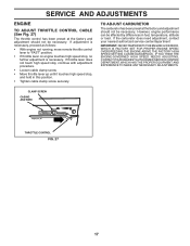
... ANY NECESSARY ADJUSTMENTS. CLAMP SCREW CASING AND WIRE engine_art_78 THROTTLE CONTROL FIG. 27 17 If adjustment is necessary, proceed as follows: • With engine not running, move remote throttle control lever to "FAST" position. • If throttle lever on engine touches high speed stop , and hold in fuel, temperature, altitude or load. If the carburetor does need adjustment, contact your nearest authorized service center/department IMPORTANT: NEVERTAMPERWITHTHEENGINEGOVERNOR, WHICH IS FACTORY SET FOR PROPER ENGINE SPEED.
... ANY NECESSARY ADJUSTMENTS. CLAMP SCREW CASING AND WIRE engine_art_78 THROTTLE CONTROL FIG. 27 17 If adjustment is necessary, proceed as follows: • With engine not running, move remote throttle control lever to "FAST" position. • If throttle lever on engine touches high speed stop , and hold in fuel, temperature, altitude or load. If the carburetor does need adjustment, contact your nearest authorized service center/department IMPORTANT: NEVERTAMPERWITHTHEENGINEGOVERNOR, WHICH IS FACTORY SET FOR PROPER ENGINE SPEED.
User Manual
Page 18
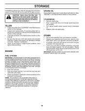
... drain the gas tank and carburetor if using fuel stabilizer. ENGINE OIL Drain oil (with engine warm) and replace with a suitable protective cover that all rusted or chipped paint surfaces; OTHER • Do not store gasoline from dust and dirt. • Cover your can if your unit with clean oil. (See "ENGINE" in minimizing the formation of oil through spark plug hole into cylinder. • Pull starter handle slowly several times to distribute oil. • Replace...
... drain the gas tank and carburetor if using fuel stabilizer. ENGINE OIL Drain oil (with engine warm) and replace with a suitable protective cover that all rusted or chipped paint surfaces; OTHER • Do not store gasoline from dust and dirt. • Cover your can if your unit with clean oil. (See "ENGINE" in minimizing the formation of oil through spark plug hole into cylinder. • Pull starter handle slowly several times to distribute oil. • Replace...
User Manual
Page 19
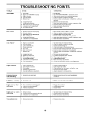
...Drive control bar is off pulley(s). 1. Inspect/adjust V-belt. 3. Tilling too deep. 2. Clogged fuel tank. 7. See "TO START ENGINE" in fuel. 6. Wait several minutes before attempting to start TROUBLESHOOTING POINTS CAUSE 1. Oil in Operation section. 3. Water in fuel. 8. Carburetor out of power 1. Clean/replace muffler. 12. Clean cylinder fins, air screen, and muffler area. 4. Engine runs but labors when tilling 1. Hard to richer position. Bad spark plug or improper gap. 4. Clogged fuel tank. 9. Check oil level/change oil...
...Drive control bar is off pulley(s). 1. Inspect/adjust V-belt. 3. Tilling too deep. 2. Clogged fuel tank. 7. See "TO START ENGINE" in fuel. 6. Wait several minutes before attempting to start TROUBLESHOOTING POINTS CAUSE 1. Oil in Operation section. 3. Water in fuel. 8. Carburetor out of power 1. Clean/replace muffler. 12. Clean cylinder fins, air screen, and muffler area. 4. Engine runs but labors when tilling 1. Hard to richer position. Bad spark plug or improper gap. 4. Clogged fuel tank. 9. Check oil level/change oil...

User Manual
Page 20
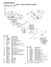
... 9484R Clip 26 159231 Cable, Clutch 27 73900400 Nut Hex Flange 1/4-20 Unc 29 73731000 Nut, Keps #10-24 UNC 30 104164X Tie, Cable 31 150696 Bolt, Pivot 33 72140404 Bolt, Carriage 1/4-20 UNC x 1/2 37 102604X Grip, Bar, Control 41 102744X Clamp, Bar, Control NOTE: All component dimensions given in U.S. Lever, Lock, Handle KEY PART NO. REPAIR PARTS TILLER - - NO. inches. 1 inch = 25.4 mm 20 MODEL NUMBER PRRT65B HANDLE ASSEMBLY KEY PART NO. NO. 1 180634 2 9266R...
... 9484R Clip 26 159231 Cable, Clutch 27 73900400 Nut Hex Flange 1/4-20 Unc 29 73731000 Nut, Keps #10-24 UNC 30 104164X Tie, Cable 31 150696 Bolt, Pivot 33 72140404 Bolt, Carriage 1/4-20 UNC x 1/2 37 102604X Grip, Bar, Control 41 102744X Clamp, Bar, Control NOTE: All component dimensions given in U.S. Lever, Lock, Handle KEY PART NO. REPAIR PARTS TILLER - - NO. inches. 1 inch = 25.4 mm 20 MODEL NUMBER PRRT65B HANDLE ASSEMBLY KEY PART NO. NO. 1 180634 2 9266R...
User Manual
Page 21
... 130812 Sheave, Engine 38 74760544 Bolt, Fin Hex 5/16-18 UNC x 2-3/4 39 140062 Cap, Plunger Blk 40 170488 Screw Hex Wsh Slt #10-24 x 1/2 43 69180 Nut, Lock #10-24 44 73800500 Nut Lock Hex w/Ins 5/16-18 Unc PL 65 73970500 Nut Lock Hex Flange NOTE: All component dimensions given in U.S. inches. 1 inch = 25.4 mm 21 MODEL NUMBER PRRT65B MAINFRAME, LEFT SIDE KEY PART NO.
... 130812 Sheave, Engine 38 74760544 Bolt, Fin Hex 5/16-18 UNC x 2-3/4 39 140062 Cap, Plunger Blk 40 170488 Screw Hex Wsh Slt #10-24 x 1/2 43 69180 Nut, Lock #10-24 44 73800500 Nut Lock Hex w/Ins 5/16-18 Unc PL 65 73970500 Nut Lock Hex Flange NOTE: All component dimensions given in U.S. inches. 1 inch = 25.4 mm 21 MODEL NUMBER PRRT65B MAINFRAME, LEFT SIDE KEY PART NO.

User Manual
Page 23
... 21 102115X 22 6803J 23 102111X DESCRIPTION Transmission Assembly (Includes Key Nos. 2-53) Gearcase, L.H. w/Bearing (In- cludes Key No. 8) 49 132688 Shaft, Tine 50 106147X Chain, Roller #50-50 Pitch 51 17720408 Screw 1/4-20 x 1/2 52 73220500 Nut, Hex 5/16-18 53 165140 Kit, Bearing 58 179520 Bolt Shoulder 60 6855M Fitting Grease - - 6066J Grease, Plastilube #1 NOTE: All component dimensions given...
... 21 102115X 22 6803J 23 102111X DESCRIPTION Transmission Assembly (Includes Key Nos. 2-53) Gearcase, L.H. w/Bearing (In- cludes Key No. 8) 49 132688 Shaft, Tine 50 106147X Chain, Roller #50-50 Pitch 51 17720408 Screw 1/4-20 x 1/2 52 73220500 Nut, Hex 5/16-18 53 165140 Kit, Bearing 58 179520 Bolt Shoulder 60 6855M Fitting Grease - - 6066J Grease, Plastilube #1 NOTE: All component dimensions given...
User Manual
Page 26
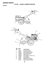
REPAIR PARTS TILLER - - MODEL NUMBER PRRT65B DECALS 1 2 4 5 6 7 9 14 13 11 KEY PART NO. NO. 1 173196 2 176303 4 180816 5 110614X 6 102180X 7 162384 9 120076X 11 173538 13 173698 14 173248 - - 181121 - - 181122 DESCRIPTION Decal, CNTRL PNL Decal, Decal, Blt Grd Decal, Instruction, Tilling Decal, Hand Placement Decal, Shift Indicator Decal, caution Decal, Warning, Rotating Tines Decal, Rewind Decal, B&S Tank Decal, B&S Air Cleaner Manual, Owner's (English) Manual, Owner's (French) 26
REPAIR PARTS TILLER - - MODEL NUMBER PRRT65B DECALS 1 2 4 5 6 7 9 14 13 11 KEY PART NO. NO. 1 173196 2 176303 4 180816 5 110614X 6 102180X 7 162384 9 120076X 11 173538 13 173698 14 173248 - - 181121 - - 181122 DESCRIPTION Decal, CNTRL PNL Decal, Decal, Blt Grd Decal, Instruction, Tilling Decal, Hand Placement Decal, Shift Indicator Decal, caution Decal, Warning, Rotating Tines Decal, Rewind Decal, B&S Tank Decal, B&S Air Cleaner Manual, Owner's (English) Manual, Owner's (French) 26
User Manual
Page 27
... workmanship. This Warranty does not apply to any power equipment unit or attachment are belts, tines, tine adapters, normal wear, normal adjustments, standard hardware and normal maintenance. 6. Exclusions: Excluded from defects in materials and workmanship. Electrolux Canada Corp. 250 Bobby Jones Expressway 7075 Ordan Drive Augusta, GA 30909 USA Mississauga, Ontario L5T 1K6 giving the model number, serial number and date of...
... workmanship. This Warranty does not apply to any power equipment unit or attachment are belts, tines, tine adapters, normal wear, normal adjustments, standard hardware and normal maintenance. 6. Exclusions: Excluded from defects in materials and workmanship. Electrolux Canada Corp. 250 Bobby Jones Expressway 7075 Ordan Drive Augusta, GA 30909 USA Mississauga, Ontario L5T 1K6 giving the model number, serial number and date of...
User Manual
Page 28
As with all mechanical products, some adjustments or part replacement may be directed to rigid quality standards. FOR SERVICE OR REPLACEMENT PARTS: 1. Consult the yellow pages of your phone directory for Trimmers, Brushcutters, and Blowers). 3. PARTS AND SERVICE Your POULAN PRO product has been expertly engineered and carefully manufactured to your local dealer(s). Number b. NOTE: Electrolux Home Products provides parts and service through its products. The philosophy...
As with all mechanical products, some adjustments or part replacement may be directed to rigid quality standards. FOR SERVICE OR REPLACEMENT PARTS: 1. Consult the yellow pages of your phone directory for Trimmers, Brushcutters, and Blowers). 3. PARTS AND SERVICE Your POULAN PRO product has been expertly engineered and carefully manufactured to your local dealer(s). Number b. NOTE: Electrolux Home Products provides parts and service through its products. The philosophy...


