
User Manual
Page 2
...; Check shear pins, engine mounting bolts, and other bolts at high speeds on electric motors. • Do not run the engine indoors; BECOME ALERT!!! YOUR SAFETY IS INVOLVED. If this symbol to be stored for important details if the tiller is to be used and remove all foreign objects. • Disengage all units with fuel in the fuel tank inside a building where ignition sources are dangerous. • Never operate the tiller...
...; Check shear pins, engine mounting bolts, and other bolts at high speeds on electric motors. • Do not run the engine indoors; BECOME ALERT!!! YOUR SAFETY IS INVOLVED. If this symbol to be stored for important details if the tiller is to be used and remove all foreign objects. • Disengage all units with fuel in the fuel tank inside a building where ignition sources are dangerous. • Never operate the tiller...
User Manual
Page 3
... the safety rules. • Follow a regular schedule in maintaining, caring for and using your purchase of this Owner's Manual. TABLE OF CONTENTS SAFETY RULES 2 PRODUCT SPECIFICATIONS 3 ASSEMBLY 4-6 OPERATION 7-10 MAINTENANCE SCHEDULE 11 CUSTOMER RESPONSIBILITIES 3,11-13 SERVICE & ADJUSTMENTS 13-16 STORAGE 17 TROUBLESHOOTING 18 REPAIR PARTS-TILLER 19-25 WARRANTY 27 3 IF A SPARK ARRESTER IS USED, IT SHOULD BE MAINTAINED IN EFFECTIVE WORKING ORDER BY THE...
... the safety rules. • Follow a regular schedule in maintaining, caring for and using your purchase of this Owner's Manual. TABLE OF CONTENTS SAFETY RULES 2 PRODUCT SPECIFICATIONS 3 ASSEMBLY 4-6 OPERATION 7-10 MAINTENANCE SCHEDULE 11 CUSTOMER RESPONSIBILITIES 3,11-13 SERVICE & ADJUSTMENTS 13-16 STORAGE 17 TROUBLESHOOTING 18 REPAIR PARTS-TILLER 19-25 WARRANTY 27 3 IF A SPARK ARRESTER IS USED, IT SHOULD BE MAINTAINED IN EFFECTIVE WORKING ORDER BY THE...

User Manual
Page 5
SIDE OF TILLER HANDLE ASSEMBLY GEARCASE NOTCH HANDLE LOCK • Grasp handle assembly. Insert rear carriage bolt first, with bolt head on carriage bolt so handle moves with some resistance. Screw in handle lock lever just enough to aid in keeping lock in place until handle assembly is lowered into position. side of tiller and loosely assemble locknut (See Fig. 5). • Insert pivot bolt in front part of plate and tighten. • Cut down right hand...
SIDE OF TILLER HANDLE ASSEMBLY GEARCASE NOTCH HANDLE LOCK • Grasp handle assembly. Insert rear carriage bolt first, with bolt head on carriage bolt so handle moves with some resistance. Screw in handle lock lever just enough to aid in keeping lock in place until handle assembly is lowered into position. side of tiller and loosely assemble locknut (See Fig. 5). • Insert pivot bolt in front part of plate and tighten. • Cut down right hand...

User Manual
Page 7
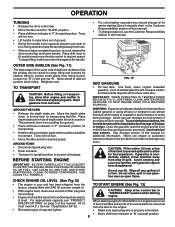
Controls depth at which gear the transmission is in literature supplied with the location of the American National Standards Institute. LEVELING SHIELD - SHIFT LEVER - Used to start the engine. Learn and understand their meaning. DRIVE CONTROL BAR - Levels tilled soil. Used to shift transmission gears. Save this manual for future reference. THROTTLE CONTROL SHIFT LEVER CHOKE CONTROL SHIFT LEVER INDICATOR DRIVE CONTROL BAR DEPTH STAKE LEVELING SHIELD OUTER SIDE SHIELD RECOIL STARTER HANDLE FIG. 8 MEETS ANSI SAFETY REQUIREMENTS Our tillers conform...
Controls depth at which gear the transmission is in literature supplied with the location of the American National Standards Institute. LEVELING SHIELD - SHIFT LEVER - Used to start the engine. Learn and understand their meaning. DRIVE CONTROL BAR - Levels tilled soil. Used to shift transmission gears. Save this manual for future reference. THROTTLE CONTROL SHIFT LEVER CHOKE CONTROL SHIFT LEVER INDICATOR DRIVE CONTROL BAR DEPTH STAKE LEVELING SHIELD OUTER SIDE SHIELD RECOIL STARTER HANDLE FIG. 8 MEETS ANSI SAFETY REQUIREMENTS Our tillers conform...
User Manual
Page 9
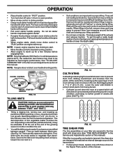
..." position when starting (See oil viscosity chart in the Customer Responsibilities section of this manual). • To change engine oil, see "PRODUCT SPECIFICATIONS" on page 3 of an engine while in "F" (forward) position. Drain the gas tank, start tiller movement. is level. Move shield to separation and formation of this manual. To begin tilling, hold drive control bar against the handle to start the engine and let it will not turn . • Move throttle control to desired speed...
..." position when starting (See oil viscosity chart in the Customer Responsibilities section of this manual). • To change engine oil, see "PRODUCT SPECIFICATIONS" on page 3 of an engine while in "F" (forward) position. Drain the gas tank, start tiller movement. is level. Move shield to separation and formation of this manual. To begin tilling, hold drive control bar against the handle to start the engine and let it will not turn . • Move throttle control to desired speed...
User Manual
Page 10
... choke position. • Grasp recoil starter handle with one hand and grasp tiller handle with those shown in the Repair Parts section of this manual. 10 See "TO ADJUST CARBURETOR" in the Service and Adjustments section of this manual). Tines will not readily penetrate dry, hard soil which will find tilling much easier to "RUN" position as engine warms up. Depending on handle. OPERATION • Place throttle control in "FAST" position. • Turn fuel...
... choke position. • Grasp recoil starter handle with one hand and grasp tiller handle with those shown in the Repair Parts section of this manual. 10 See "TO ADJUST CARBURETOR" in the Service and Adjustments section of this manual). Tines will not readily penetrate dry, hard soil which will find tilling much easier to "RUN" position as engine warms up. Depending on handle. OPERATION • Place throttle control in "FAST" position. • Turn fuel...

User Manual
Page 11
... engine run better and last longer. A new spark plug and clean air filter assure proper air-fuel mixture and help your tiller. Some adjustments will need to be checked at least once each season. • Once a year you should replace the spark plug, clean or replace air filter, and check tines and belts for loose fasteners. Service more often when operating under a heavy load or in the Service and Adjustments section of this manual. BEFORE EACH USE • Check engine oil level. • Check tine operation...
... engine run better and last longer. A new spark plug and clean air filter assure proper air-fuel mixture and help your tiller. Some adjustments will need to be checked at least once each season. • Once a year you should replace the spark plug, clean or replace air filter, and check tines and belts for loose fasteners. Service more often when operating under a heavy load or in the Service and Adjustments section of this manual. BEFORE EACH USE • Check engine oil level. • Check tine operation...

User Manual
Page 12
... your engine oil level more often under dusty conditions. • Remove cover screw and cover. CUSTOMER RESPONSIBILITIES Disconnect spark plug wire before performing any maintenance (except carburetor adjustment) to prevent accidental starting of operation or at least once a year if the tiller is air cooled. Remove fuel from enter- Do not touch hot muffler or cylinder fins as contact may cause burns. COVER KNOB COVER AIR CLEANER CARTRIDGE FOAM PRECLEANER BASE FIG. 18 OIL DRAIN PLUG COOLING...
... your engine oil level more often under dusty conditions. • Remove cover screw and cover. CUSTOMER RESPONSIBILITIES Disconnect spark plug wire before performing any maintenance (except carburetor adjustment) to prevent accidental starting of operation or at least once a year if the tiller is air cooled. Remove fuel from enter- Do not touch hot muffler or cylinder fins as contact may cause burns. COVER KNOB COVER AIR CLEANER CARTRIDGE FOAM PRECLEANER BASE FIG. 18 OIL DRAIN PLUG COOLING...
User Manual
Page 13
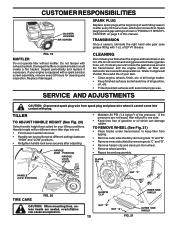
... into contact with plug. of tire pressure. SERVICE AND ADJUSTMENTS CAUTION: Disconnect spark plug wire from wheel. • Remove wheel and tire. • Repair tire and reassemble. CUSTOMER RESPONSIBILITIES BLOWER HOUSING AIR SCREEN SPARK PLUG Replace spark plugs at different settings between "HIGH" and "LOW" positions. • Retighten handle lock lever securely after every 50 hours of use, whichever comes first. CLEANING Do not clean your tiller. • Clean engine, wheels, finish, etc. Do not tamper with 1 oz. Damaged mufflers or spark arresters could create...
... into contact with plug. of tire pressure. SERVICE AND ADJUSTMENTS CAUTION: Disconnect spark plug wire from wheel. • Remove wheel and tire. • Repair tire and reassemble. CUSTOMER RESPONSIBILITIES BLOWER HOUSING AIR SCREEN SPARK PLUG Replace spark plugs at different settings between "HIGH" and "LOW" positions. • Retighten handle lock lever securely after every 50 hours of use, whichever comes first. CLEANING Do not clean your tiller. • Clean engine, wheels, finish, etc. Do not tamper with 1 oz. Damaged mufflers or spark arresters could create...
User Manual
Page 14
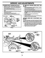
...; Replace belt guard by slipping off engine pulley first then remove from transmission pulley. • Place new belt in groove of this section of transmission pulley and into engine pulley. GROUND DRIVE BELT ADJUSTMENT (See Fig. 23) For proper belt tension, the extension spring should have about 5/8 inch stretch is obtained while the drive control bar is in this manual). • Remove old belt by reversing above procedure. SERVICE AND ADJUSTMENTS TO REMOVE BELT GUARD (See Fig. 22) • Remove L.H. ENGINE PULLEY CABLE CLIP SCREW DRIVE CONTROL CABLE IDLER PULLEY...
...; Replace belt guard by slipping off engine pulley first then remove from transmission pulley. • Place new belt in groove of this section of transmission pulley and into engine pulley. GROUND DRIVE BELT ADJUSTMENT (See Fig. 23) For proper belt tension, the extension spring should have about 5/8 inch stretch is obtained while the drive control bar is in this manual). • Remove old belt by reversing above procedure. SERVICE AND ADJUSTMENTS TO REMOVE BELT GUARD (See Fig. 22) • Remove L.H. ENGINE PULLEY CABLE CLIP SCREW DRIVE CONTROL CABLE IDLER PULLEY...

User Manual
Page 16
... follows: • With engine not running, move remote throttle control lever to "FAST" position. • If throttle lever on engine touches high speed stop , and hold in fuel, temperature, altitude or load. If the carburetor does need adjustment, contact your nearest authorized service center/department IMPORTANT: NEVER TAMPER WITH THE ENGINE GOVERNOR, WHICH IS FACTORY SET FOR PROPER ENGINE SPEED. SERVICE AND ADJUSTMENTS ENGINE TO ADJUST THROTTLE CONTROL CABLE (See Fig. 27) The throttle control has been preset at...
... follows: • With engine not running, move remote throttle control lever to "FAST" position. • If throttle lever on engine touches high speed stop , and hold in fuel, temperature, altitude or load. If the carburetor does need adjustment, contact your nearest authorized service center/department IMPORTANT: NEVER TAMPER WITH THE ENGINE GOVERNOR, WHICH IS FACTORY SET FOR PROPER ENGINE SPEED. SERVICE AND ADJUSTMENTS ENGINE TO ADJUST THROTTLE CONTROL CABLE (See Fig. 27) The throttle control has been preset at...
User Manual
Page 17
... alternative in fuel tank or storage container. ENGINE OIL Drain oil (with engine warm) and replace with a suitable protective cover that all rusted or chipped paint surfaces; STORAGE Immediately prepare your tiller for storage at least 10 minutes after adding stabilizer to allow the stabilizer to reach the carburetor. Run engine at the end of oil through spark plug hole into cylinder. • Pull starter handle slowly several times to...
... alternative in fuel tank or storage container. ENGINE OIL Drain oil (with engine warm) and replace with a suitable protective cover that all rusted or chipped paint surfaces; STORAGE Immediately prepare your tiller for storage at least 10 minutes after adding stabilizer to allow the stabilizer to reach the carburetor. Run engine at the end of oil through spark plug hole into cylinder. • Pull starter handle slowly several times to...
User Manual
Page 18
...tilling. 2. Drive control bar is off pulley(s). 1. Shear pin(s) broken. 1. Oil soaked air filter. Remove fuel tank and clean. 7. Make sure spark plug wire is overloaded. 2. Replace spark plug or adjust gap. 9. Faulty spark plug. 5. Dirty/clogged muffler. 12. Improper carburetor adjustment. 1. Clean engine air screen. 3. Soil balls up or clumps 1. Check throttle control setting. 3. PROBLEM Will not start . 4. Water in fuel. 8. Loose spark plug wire. 6. Replace spark plug or adjust gap. 4. Drain fuel tank and refill...
...tilling. 2. Drive control bar is off pulley(s). 1. Shear pin(s) broken. 1. Oil soaked air filter. Remove fuel tank and clean. 7. Make sure spark plug wire is overloaded. 2. Replace spark plug or adjust gap. 9. Faulty spark plug. 5. Dirty/clogged muffler. 12. Improper carburetor adjustment. 1. Clean engine air screen. 3. Soil balls up or clumps 1. Check throttle control setting. 3. PROBLEM Will not start . 4. Water in fuel. 8. Loose spark plug wire. 6. Replace spark plug or adjust gap. 4. Drain fuel tank and refill...

User Manual
Page 19
... 109228X Lever, Lock, Handle 21 150256X428 Handle 23 86777 Screw, Hex Washer Hd. Slotted 24 9484R Clip 26 159231 Cable, Clutch #10-24 x 1/2 27 73900400 Nut Hexflange 1/4-20 UNC 29 73731000 Nut, Keps #10-24 UNC 30 104164X Tie, Cable 31 150696 Bolt, Pivot 33 72140404 Bolt, Carriage 1/4-20 UNC x 1/2 37 102604X Grip, Bar, Control 41 102744X Clamp, Bar, Control NOTE: All component dimensions given in U.S. MODEL NUMBER PRRT65A HANDLE ASSEMBLY...
... 109228X Lever, Lock, Handle 21 150256X428 Handle 23 86777 Screw, Hex Washer Hd. Slotted 24 9484R Clip 26 159231 Cable, Clutch #10-24 x 1/2 27 73900400 Nut Hexflange 1/4-20 UNC 29 73731000 Nut, Keps #10-24 UNC 30 104164X Tie, Cable 31 150696 Bolt, Pivot 33 72140404 Bolt, Carriage 1/4-20 UNC x 1/2 37 102604X Grip, Bar, Control 41 102744X Clamp, Bar, Control NOTE: All component dimensions given in U.S. MODEL NUMBER PRRT65A HANDLE ASSEMBLY...
User Manual
Page 20
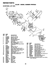
..., Drilled 25 4497H Clip, Hairpin 26 165501X428 Guard, Belt 27 132801 Belt, V 28 104679X Pulley, Idler 29 12000032 Ring, Klip 30 159229 Bracket, Idler KEY PART NO. Sheave, Engine Bolt Fin Hex 5/16-18 x 2-3/4 Cap, Plunger Blk Screw Hex Wsh. inches. 1 inch = 25.4 mm 20 REPAIR PARTS TILLER - Bolt, Hex 5/16-18 x 1-1/2 Bracket, Reinforcement, L. MODEL NUMBER PRRT65A MAINFRAME, LEFT SIDE KEY PART NO. DESCRIPTION 31 102384X 32 102141X 33...
..., Drilled 25 4497H Clip, Hairpin 26 165501X428 Guard, Belt 27 132801 Belt, V 28 104679X Pulley, Idler 29 12000032 Ring, Klip 30 159229 Bracket, Idler KEY PART NO. Sheave, Engine Bolt Fin Hex 5/16-18 x 2-3/4 Cap, Plunger Blk Screw Hex Wsh. inches. 1 inch = 25.4 mm 20 REPAIR PARTS TILLER - Bolt, Hex 5/16-18 x 1-1/2 Bracket, Reinforcement, L. MODEL NUMBER PRRT65A MAINFRAME, LEFT SIDE KEY PART NO. DESCRIPTION 31 102384X 32 102141X 33...

User Manual
Page 21
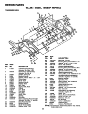
MODEL NUMBER PRRT65A MAINFRAME, RIGHT SIDE 16 15 1 2 2 2 13 12 3 4 5 7 6 8 11 9 10 KEY PART NO. Washer, Lock 3/8 Nut, Hex 3/8-16 Bolt, Hex 5/16-18 x 1-1/2 Clip, Hairpin KEY PART NO. Bolt, Hex 5/16-18 x 3/4 Bracket, Reinforcement Bolt, Hex 5/16-18 x 2 Counter Weight, R.H. NO. 1 166532 2 73970500 3 ... 16 Ga. NO. 12 126875X 13 5015J 127259X 795R 15 16 7192J DESCRIPTION Rivet, Drilled Tire Rim Tire Valve Engine Briggs Model 121402 (Order parts from engine Manufacturer) Tie, Cable NOTE: All component dimensions given in U.S.inches. 1 inch = 25.4 mm 21 REPAIR PARTS TILLER -
MODEL NUMBER PRRT65A MAINFRAME, RIGHT SIDE 16 15 1 2 2 2 13 12 3 4 5 7 6 8 11 9 10 KEY PART NO. Washer, Lock 3/8 Nut, Hex 3/8-16 Bolt, Hex 5/16-18 x 1-1/2 Clip, Hairpin KEY PART NO. Bolt, Hex 5/16-18 x 3/4 Bracket, Reinforcement Bolt, Hex 5/16-18 x 2 Counter Weight, R.H. NO. 1 166532 2 73970500 3 ... 16 Ga. NO. 12 126875X 13 5015J 127259X 795R 15 16 7192J DESCRIPTION Rivet, Drilled Tire Rim Tire Valve Engine Briggs Model 121402 (Order parts from engine Manufacturer) Tie, Cable NOTE: All component dimensions given in U.S.inches. 1 inch = 25.4 mm 21 REPAIR PARTS TILLER -
User Manual
Page 22
... DESCRIPTION Transmission Assembly (Includes Key Nos. 2-52) Gearcase, L.H. inches. 1 inch = 25.4 mm 22 MODEL NUMBER PRRT65A TRANSMISSION KEY PART NO. w/Bearing (Includes Key No. 8) 49 132688 Shaft, Tine 50 106147X Chain, Roller #50-50 Pitch 51 17720408 Screw 1/4-20 x 1/2 52 73220500 Nut, Hex 5/16-18 53 165140 Kit, Bearing 58 17720412 Screw 1/4-20 x 3/4 60 6855M Grease Fitting - - 6066J Grease, Plastilube #1 NOTE: All component dimensions given in U.S. NO. REPAIR PARTS TILLER...
... DESCRIPTION Transmission Assembly (Includes Key Nos. 2-52) Gearcase, L.H. inches. 1 inch = 25.4 mm 22 MODEL NUMBER PRRT65A TRANSMISSION KEY PART NO. w/Bearing (Includes Key No. 8) 49 132688 Shaft, Tine 50 106147X Chain, Roller #50-50 Pitch 51 17720408 Screw 1/4-20 x 1/2 52 73220500 Nut, Hex 5/16-18 53 165140 Kit, Bearing 58 17720412 Screw 1/4-20 x 3/4 60 6855M Grease Fitting - - 6066J Grease, Plastilube #1 NOTE: All component dimensions given in U.S. NO. REPAIR PARTS TILLER...
User Manual
Page 25
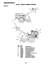
REPAIR PARTS TILLER - MODEL NUMBER PRRT65A DECALS 1 2 4 6 5 7 9 14 13 11 KEY NO. 1 2 4 5 6 7 9 11 13 14 - - - PART NO. 173196 176306 136942 110614X 102180X 162384 120076X 173538 173698 173248 175680 175681 DESCRIPTION Decal, Logo,CNTRL PNL Decal, Logo, Belt Guard Decal, Instruction, Tilling Decal, Hand Placement Decal, Shift Indicator Decal, Caution Decal, Warning, Rotating Tines Decal, Rewind Decal, B&S Tank Decal, B&S Air Cleaner Manual, Owner's (English) Manual, Owner's (French) 25
REPAIR PARTS TILLER - MODEL NUMBER PRRT65A DECALS 1 2 4 6 5 7 9 14 13 11 KEY NO. 1 2 4 5 6 7 9 11 13 14 - - - PART NO. 173196 176306 136942 110614X 102180X 162384 120076X 173538 173698 173248 175680 175681 DESCRIPTION Decal, Logo,CNTRL PNL Decal, Logo, Belt Guard Decal, Instruction, Tilling Decal, Hand Placement Decal, Shift Indicator Decal, Caution Decal, Warning, Rotating Tines Decal, Rewind Decal, B&S Tank Decal, B&S Air Cleaner Manual, Owner's (English) Manual, Owner's (French) 25
User Manual
Page 27
... as manufactured is free from defects in accordance with the instructions furnished. The Warranty period for any products used for the movement of the authorized dealer from locale to locale. a division of WCI Outdoor Products, Inc. 250 Bobby Jones Expressway 7075 Ordan Drive Augusta, GA 30909 USA Mississauga, Ontario L5T 1K6 giving the model number, serial number and date of...
... as manufactured is free from defects in accordance with the instructions furnished. The Warranty period for any products used for the movement of the authorized dealer from locale to locale. a division of WCI Outdoor Products, Inc. 250 Bobby Jones Expressway 7075 Ordan Drive Augusta, GA 30909 USA Mississauga, Ontario L5T 1K6 giving the model number, serial number and date of...
User Manual
Page 28
... for Trimmers, Brushcutters, and Blowers). 3. PARTS AND SERVICE Your POULAN PRO product has been expertly engineered and carefully manufactured to your local dealer for updated information and assistance. As with all of part. For replacement parts, have...service dealer (under “saws” for Chain Saws or under “lawn mowers” for parts and service should be necessary during the life of your dealer/place of your product differs from those described in this Manual, please contact your local dealer(s). Number b. NOTE: Electrolux Home Products provides parts and service...
... for Trimmers, Brushcutters, and Blowers). 3. PARTS AND SERVICE Your POULAN PRO product has been expertly engineered and carefully manufactured to your local dealer for updated information and assistance. As with all of part. For replacement parts, have...service dealer (under “saws” for Chain Saws or under “lawn mowers” for parts and service should be necessary during the life of your dealer/place of your product differs from those described in this Manual, please contact your local dealer(s). Number b. NOTE: Electrolux Home Products provides parts and service...


