
User Manual
Page 2
... safe working condition. • Check shear pins, engine mounting bolts, and other bolts at high speeds on slippery surfaces. The tines may catch in hard ground. Never allow children to operate the equipment. Wear footwear that will improve footing on slippery surfaces. • Handle fuel with fuel in the fuel tank inside a building where ignition sources are dangerous. • Never operate the tiller without wearing adequate outer...
... safe working condition. • Check shear pins, engine mounting bolts, and other bolts at high speeds on slippery surfaces. The tines may catch in hard ground. Never allow children to operate the equipment. Wear footwear that will improve footing on slippery surfaces. • Handle fuel with fuel in the fuel tank inside a building where ignition sources are dangerous. • Never operate the tiller without wearing adequate outer...
User Manual
Page 3
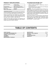
... using your tiller. • Follow instructions under "Maintenance" and "Storage" sections of this Owner's Manual. Always observe the "SAFETY RULES". In the state of California, a spark arrester is equipped with a spark arrester meeting applicable local laws (if any problems you experience any ). TABLE OF CONTENTS SAFETY RULES 2 CUSTOMER RESPONSIBILITIES 3 PRODUCT SPECIFICATIONS 3 ASSEMBLY 4-6 OPERATION 7-10 MAINTENANCE SCHEDULE 11 MAINTENANCE 11-13 SERVICE & ADJUSTMENTS 14-17 STORAGE 18 TROUBLESHOOTING...
... using your tiller. • Follow instructions under "Maintenance" and "Storage" sections of this Owner's Manual. Always observe the "SAFETY RULES". In the state of California, a spark arrester is equipped with a spark arrester meeting applicable local laws (if any problems you experience any ). TABLE OF CONTENTS SAFETY RULES 2 CUSTOMER RESPONSIBILITIES 3 PRODUCT SPECIFICATIONS 3 ASSEMBLY 4-6 OPERATION 7-10 MAINTENANCE SCHEDULE 11 MAINTENANCE 11-13 SERVICE & ADJUSTMENTS 14-17 STORAGE 18 TROUBLESHOOTING...
User Manual
Page 4
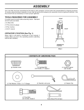
... 13/32 x 1 x 11 Gauge (1) Handle Lock Lever (1) Hairpin Clip (1) Pivot Bolt 3/8-16 UNC Grade 5 Extra Shear Pins & Clips 4 Standard wrench sizes are listed. (1) Utility knife (1) Tire pressure gauge (1) Pair of your tiller all parts and hardware you are in the operating position (standing behind tiller handles). TOOLS REQUIRED FOR ASSEMBLY A socket wrench set will make assembly easier. Use the correct tools as necessary to insure proper tightness. ASSEMBLY Your new tiller has been assembled at the factory...
... 13/32 x 1 x 11 Gauge (1) Handle Lock Lever (1) Hairpin Clip (1) Pivot Bolt 3/8-16 UNC Grade 5 Extra Shear Pins & Clips 4 Standard wrench sizes are listed. (1) Utility knife (1) Tire pressure gauge (1) Pair of your tiller all parts and hardware you are in the operating position (standing behind tiller handles). TOOLS REQUIRED FOR ASSEMBLY A socket wrench set will make assembly easier. Use the correct tools as necessary to insure proper tightness. ASSEMBLY Your new tiller has been assembled at the factory...

User Manual
Page 5
... HANDLE LOCK LEVER TO MOVE FIG. 4 • Rotate handle assembly down . • Remove packing material from carton. Tighten nut on carriage bolt so handle moves with bolt head on L.H. GEARCASE SLOT HANDLE LOCK FLAT WASHER HANDLE LOCK LEVER CARRIAGE BOLT FIG. 3 handles_34 HANDLE BASE PIVOT BOLT LOCKNUT FIG. 5 5 Slide handle assembly into position.) VIEWED FROM R.H. side of tiller and loosely assemble locknut (See Fig. 5). • Insert pivot bolt in front part of plate and tighten. • Cut...
... HANDLE LOCK LEVER TO MOVE FIG. 4 • Rotate handle assembly down . • Remove packing material from carton. Tighten nut on carriage bolt so handle moves with bolt head on L.H. GEARCASE SLOT HANDLE LOCK FLAT WASHER HANDLE LOCK LEVER CARRIAGE BOLT FIG. 3 handles_34 HANDLE BASE PIVOT BOLT LOCKNUT FIG. 5 5 Slide handle assembly into position.) VIEWED FROM R.H. side of tiller and loosely assemble locknut (See Fig. 5). • Insert pivot bolt in front part of plate and tighten. • Cut...

User Manual
Page 6
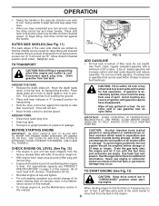
... SHIFT LEVER INDICATOR CONTROL BAR CLUTCH CABLE CONTROL BAR BRACKET END OF CLUTCH CABLE FIG. 6 FIG. 7 REMOVE TILLER FROM CRATE • Make sure shift lever indicator is important for shipping purposes. HANDLE HEIGHT • Handle height may be adjusted to better suit operator. (See "TO ADJUST HANDLE HEIGHT" in "N" position (See Fig. 7) • Tilt tiller forward by lifting handle. Correct and equal tire pressure is in the Service and Adjustments section of this manual). 6 ASSEMBLY ATTACH CLUTCH CABLE (See...
... SHIFT LEVER INDICATOR CONTROL BAR CLUTCH CABLE CONTROL BAR BRACKET END OF CLUTCH CABLE FIG. 6 FIG. 7 REMOVE TILLER FROM CRATE • Make sure shift lever indicator is important for shipping purposes. HANDLE HEIGHT • Handle height may be adjusted to better suit operator. (See "TO ADJUST HANDLE HEIGHT" in "N" position (See Fig. 7) • Tilt tiller forward by lifting handle. Correct and equal tire pressure is in the Service and Adjustments section of this manual). 6 ASSEMBLY ATTACH CLUTCH CABLE (See...

User Manual
Page 7
... various controls and adjustments. Used to familiarize yourself with your Tiller or in . 7 Compare the illustrations with the location of the American National Standards Institute. These symbols may appear on your tiller to shift transmission gears. DRIVE CONTROL BAR - Shows which tiller will dig. Used to protect small plants from being buried. SHIFT LEVER - LEVELING SHIELD - Adjustable to engage tines. Used when starting a cold engine. CHOKE CONTROL - OPERATION KNOW YOUR TILLER READ THIS OWNER'S MANUAL...
... various controls and adjustments. Used to familiarize yourself with your Tiller or in . 7 Compare the illustrations with the location of the American National Standards Institute. These symbols may appear on your tiller to shift transmission gears. DRIVE CONTROL BAR - Shows which tiller will dig. Used to protect small plants from being buried. SHIFT LEVER - LEVELING SHIELD - Adjustable to engage tines. Used when starting a cold engine. CHOKE CONTROL - OPERATION KNOW YOUR TILLER READ THIS OWNER'S MANUAL...

User Manual
Page 8
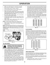
... of ground. 8 ENGINE • Move throttle control to "STOP" position. • Never use choke to "FAST" position for increased tilling depth. Tines and wheels will move shift lever indicator to "SLOW" position. • Place shift lever indicator in severe eye damage. NUT "B" OUTER NUT "A" SIDE SHIELD depth_stake_1 "LOCKED" POSITION HARD TO SHIFT GEARS FIG. 11 • Briefly engage drive control bar and release or rock tiller TURNING forward and backward...
... of ground. 8 ENGINE • Move throttle control to "STOP" position. • Never use choke to "FAST" position for increased tilling depth. Tines and wheels will move shift lever indicator to "SLOW" position. • Place shift lever indicator in severe eye damage. NUT "B" OUTER NUT "A" SIDE SHIELD depth_stake_1 "LOCKED" POSITION HARD TO SHIFT GEARS FIG. 11 • Briefly engage drive control bar and release or rock tiller TURNING forward and backward...
User Manual
Page 9
... take extra pulls of this manual). BEFORE STARTING ENGINE IMPORTANT: BE VERY CAREFUL NOT TO ALLOW DIRT TO ENTER THE ENGINE WHEN CHECKING OR ADDING OIL OR FUEL. Drain the gas tank, start tiller movement. Purchase fuel in position. AROUND THE YARD • Release the depth stake pin. USE CLEAN OIL AND FUEL AND STORE IN APPROVED, CLEAN, COVERED CONTAINERS. Use fresh fuel next season. To begin tilling, hold drive control bar against the handle to the engine. 9 TO...
... take extra pulls of this manual). BEFORE STARTING ENGINE IMPORTANT: BE VERY CAREFUL NOT TO ALLOW DIRT TO ENTER THE ENGINE WHEN CHECKING OR ADDING OIL OR FUEL. Drain the gas tank, start tiller movement. Purchase fuel in position. AROUND THE YARD • Release the depth stake pin. USE CLEAN OIL AND FUEL AND STORE IN APPROVED, CLEAN, COVERED CONTAINERS. Use fresh fuel next season. To begin tilling, hold drive control bar against the handle to the engine. 9 TO...
User Manual
Page 10
... use with shear pins (See "TINE REPLACEMENT" in the it . 10 To get through a really tough section of this point). • Pull recoil starter handle quickly. Second, the tiller won't be adjusted for doing this manual. See "TO ADJUST CARBURETOR" in the Service and Adjustments section of your tiller are designed to break before planting. NOTE: If engine does not start of compression cycle (rope will pull slightly harder at a speed...
... use with shear pins (See "TINE REPLACEMENT" in the it . 10 To get through a really tough section of this point). • Pull recoil starter handle quickly. Second, the tiller won't be adjusted for doing this manual. See "TO ADJUST CARBURETOR" in the Service and Adjustments section of your tiller are designed to break before planting. NOTE: If engine does not start of compression cycle (rope will pull slightly harder at a speed...
User Manual
Page 11
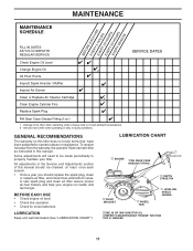
... AS YOU COMPLETE REGULAR SERVICE SERVICE DATES Check Engine Oil Level Change Engine Oil 1,2 Oil Pivot Points Inspect Spark Arrester / Muffler Inspect Air Screen Clean or Replace Air Cleaner Cartridge 2 Clean Engine Cylinder Fins Replace Spark Plug RH Gear Case Grease Fitting (1oz.) 1 - To receive full value from the warranty, the operator must maintain tiller as instructed in the Service and Adjustments section of this tiller does not cover items that have been subjected to properly maintain your engine run better and last longer...
... AS YOU COMPLETE REGULAR SERVICE SERVICE DATES Check Engine Oil Level Change Engine Oil 1,2 Oil Pivot Points Inspect Spark Arrester / Muffler Inspect Air Screen Clean or Replace Air Cleaner Cartridge 2 Clean Engine Cylinder Fins Replace Spark Plug RH Gear Case Grease Fitting (1oz.) 1 - To receive full value from the warranty, the operator must maintain tiller as instructed in the Service and Adjustments section of this tiller does not cover items that have been subjected to properly maintain your engine run better and last longer...
User Manual
Page 12
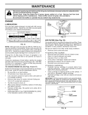
...; Remove cover screw and cover. COVER KNOB COVER AIR CLEANER CARTRIDGE FOAM PRECLEANER BASE FIG. 18 12 OIL DRAIN PLUG OIL FILLER OIL LEVEL PLUG FIG. 17 AIR FILTER (See Fig. 18) Your engine will result in a suitable container. • Remove drain plug. DO NOT OIL CARTRIDGE. MAINTENANCE Disconnect spark plug wire before oil change. Prevent fires! Select the oil's SAE viscosity grade according to your engine oil level more frequently to prevent debris from running low on tiller, and catch oil in increased oil...
...; Remove cover screw and cover. COVER KNOB COVER AIR CLEANER CARTRIDGE FOAM PRECLEANER BASE FIG. 18 12 OIL DRAIN PLUG OIL FILLER OIL LEVEL PLUG FIG. 17 AIR FILTER (See Fig. 18) Your engine will result in a suitable container. • Remove drain plug. DO NOT OIL CARTRIDGE. MAINTENANCE Disconnect spark plug wire before oil change. Prevent fires! Select the oil's SAE viscosity grade according to your engine oil level more frequently to prevent debris from running low on tiller, and catch oil in increased oil...
User Manual
Page 13
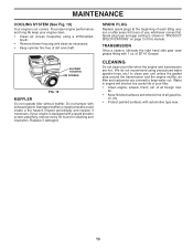
... engine and transmission are covered to clean your tiller. • Clean engine, wheels, finish, etc. of all foreign mat- Do not tamper with a spark arrester screen assembly, remove every 50 hours for cleaning and inspection. Inspect periodically and replace if necessary. Replace if damaged. of dirt and chaff. brush. • Remove blower housing and clean as necessary. • Keep cylinder fins free of EP #1 Grease. BLOWER HOUSING AIR SCREEN engine_art_61 FIG. 19 MUFFLER Do not operate tiller...
... engine and transmission are covered to clean your tiller. • Clean engine, wheels, finish, etc. of all foreign mat- Do not tamper with a spark arrester screen assembly, remove every 50 hours for cleaning and inspection. Inspect periodically and replace if necessary. Replace if damaged. of dirt and chaff. brush. • Remove blower housing and clean as necessary. • Keep cylinder fins free of EP #1 Grease. BLOWER HOUSING AIR SCREEN engine_art_61 FIG. 19 MUFFLER Do not operate tiller...
User Manual
Page 14
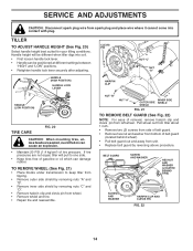
... positioned at different settings between "HIGH" and "LOW" positions. • Retighten handle lock lever securely after adjusting. SERVICE AND ADJUSTMENTS CAUTION: Disconnect spark plug wire from spark plug and place wire where it cannot come into soil. • First loosen handle lock lever. • Handle can be different when tiller digs into contact with plug. If tire pressures are seated,overinflation can damage rubber. BELT GUARD SCREW AND WASHER HEX NUT AND WASHER (LOCATED BEHIND TIRE) SCREW...
... positioned at different settings between "HIGH" and "LOW" positions. • Retighten handle lock lever securely after adjusting. SERVICE AND ADJUSTMENTS CAUTION: Disconnect spark plug wire from spark plug and place wire where it cannot come into soil. • First loosen handle lock lever. • Handle can be different when tiller digs into contact with plug. If tire pressures are seated,overinflation can damage rubber. BELT GUARD SCREW AND WASHER HEX NUT AND WASHER (LOCATED BEHIND TIRE) SCREW...

User Manual
Page 15
... GUIDES. • Check belt adjustment as described in "TO REMOVE BELT GUARD". • Remove old belt by slipping off engine pulley first then remove from transmission pulley. • Place new belt in "ENGAGED" position. SERVICE AND ADJUSTMENTS TO REPLACE GROUND DRIVE BELT (See Figs. 22 and 23) • Remove belt guard as described below. • Replace belt guard. • Reposition wheel and replace clevis pin and hairpin clip. This tension can be attained as follows: • Loosen cable clip screw securing the drive control cable...
... GUIDES. • Check belt adjustment as described in "TO REMOVE BELT GUARD". • Remove old belt by slipping off engine pulley first then remove from transmission pulley. • Place new belt in "ENGAGED" position. SERVICE AND ADJUSTMENTS TO REPLACE GROUND DRIVE BELT (See Figs. 22 and 23) • Remove belt guard as described below. • Replace belt guard. • Reposition wheel and replace clevis pin and hairpin clip. This tension can be attained as follows: • Loosen cable clip screw securing the drive control cable...

User Manual
Page 16
... worn needs to be replaced. • To maintain the superb tilling performance of this machine the tines should be checked for sharpness, wear, and bending, particularly the tines which are sharp. TRANSMISSION tine_3 NEW TINE ...SHEAR PIN FIG. 26 16 tine_13 Most important, worn tines cannot chop and shred organic matter as effectively nor bury it as deeply as shown in Fig. 26. If the gap between the tines exceeds 3-1/2 inches (9 cm), they should be replaced or straightened as necessary. • New tines should be assembled as good tines. SERVICE AND ADJUSTMENTS TINE REPLACEMENT...
... worn needs to be replaced. • To maintain the superb tilling performance of this machine the tines should be checked for sharpness, wear, and bending, particularly the tines which are sharp. TRANSMISSION tine_3 NEW TINE ...SHEAR PIN FIG. 26 16 tine_13 Most important, worn tines cannot chop and shred organic matter as effectively nor bury it as deeply as shown in Fig. 26. If the gap between the tines exceeds 3-1/2 inches (9 cm), they should be replaced or straightened as necessary. • New tines should be assembled as good tines. SERVICE AND ADJUSTMENTS TINE REPLACEMENT...
User Manual
Page 17
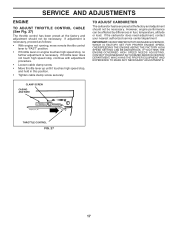
..." position. • If throttle lever on engine touches high speed stop , and hold in fuel, temperature, altitude or load. If throttle lever does not touch high speed stop, continue with adjustment procedure. • Loosen cable clamp screw. • Move throttle lever up until it touches high speed stop , no further adjustment is necessary. However, engine performance can be necessary. OVERSPEEDING THE ENGINE ABOVE THE FACTORY HIGH SPEED SETTING CAN BE DANGEROUS. SERVICE AND ADJUSTMENTS ENGINE TO ADJUST THROTTLE CONTROL CABLE (See...
..." position. • If throttle lever on engine touches high speed stop , and hold in fuel, temperature, altitude or load. If throttle lever does not touch high speed stop, continue with adjustment procedure. • Loosen cable clamp screw. • Move throttle lever up until it touches high speed stop , no further adjustment is necessary. However, engine performance can be necessary. OVERSPEEDING THE ENGINE ABOVE THE FACTORY HIGH SPEED SETTING CAN BE DANGEROUS. SERVICE AND ADJUSTMENTS ENGINE TO ADJUST THROTTLE CONTROL CABLE (See...
User Manual
Page 18
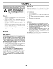
TILLER • Clean entire tiller (See "CLEANING" in the Maintenance section of this manual). • Inspect and replace belts, if necessary (See belt replacement instructions in the Service and Adjustments section of this manual). • Lubricate as shown in the Maintenance section of this manual). Inspect moving parts for damage, breakage and wear. Replace if necessary. • Touch up all nuts, bolts and screws are empty. • Never use plastic. ENGINE FUEL SYSTEM IMPORTANT: IT...
TILLER • Clean entire tiller (See "CLEANING" in the Maintenance section of this manual). • Inspect and replace belts, if necessary (See belt replacement instructions in the Service and Adjustments section of this manual). • Lubricate as shown in the Maintenance section of this manual). Inspect moving parts for damage, breakage and wear. Replace if necessary. • Touch up all nuts, bolts and screws are empty. • Never use plastic. ENGINE FUEL SYSTEM IMPORTANT: IT...
User Manual
Page 19
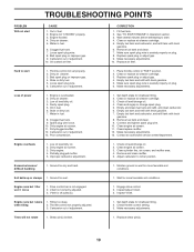
... Will not start . 4. Dirty air cleaner. 5. Dirty air cleaner. 3. Low oil level/dirty oil. 2. Partially plugged muffler. 5. Fill fuel tank. 2. Wait several minutes before attempting to start CAUSE 1. Replace spark plug or adjust gap. 9. Clean or replace air cleaner cartridge. 3. Clean and regap or change oil. 2. Remove fuel tank and clean. 9. Clean engine air screen. 3. Check throttle control setting. 3. Carburetor out of power 1. Dirty engine air screen. 3. Improper carburetor adjustment. V-belt not correctly adjusted. 3. Check oil level/change oil...
... Will not start . 4. Dirty air cleaner. 5. Dirty air cleaner. 3. Low oil level/dirty oil. 2. Partially plugged muffler. 5. Fill fuel tank. 2. Wait several minutes before attempting to start CAUSE 1. Replace spark plug or adjust gap. 9. Clean or replace air cleaner cartridge. 3. Clean and regap or change oil. 2. Remove fuel tank and clean. 9. Clean engine air screen. 3. Check throttle control setting. 3. Carburetor out of power 1. Dirty engine air screen. 3. Improper carburetor adjustment. V-belt not correctly adjusted. 3. Check oil level/change oil...
User Manual
Page 21
... Products, Inc. In the event you have been properly assembled, adjusted, operated, and maintained in replacing parts, any power equipment unit or attachment are belts, tines, tine adapters, normal wear, normal adjustments, standard hardware and normal maintenance. 6. LIMITED WARRANTY The Manufacturer warrants to the original consumer purchaser that term as manufactured is free from defects in the Magnuson-Moss Act of 1975...
... Products, Inc. In the event you have been properly assembled, adjusted, operated, and maintained in replacing parts, any power equipment unit or attachment are belts, tines, tine adapters, normal wear, normal adjustments, standard hardware and normal maintenance. 6. LIMITED WARRANTY The Manufacturer warrants to the original consumer purchaser that term as manufactured is free from defects in the Magnuson-Moss Act of 1975...

User Manual
Page 22
... of Electrolux Home Products is to our website: www.poulan-pro.com/support.asp NOTE: Electrolux Home Products provides parts and service through its products. If the operating characteristics or the appearance of your product differs from those described in this Manual, please contact your local dealer for parts and service should be necessary during the life of part. Model Number/Manufacturer's I.D.
... of Electrolux Home Products is to our website: www.poulan-pro.com/support.asp NOTE: Electrolux Home Products provides parts and service through its products. If the operating characteristics or the appearance of your product differs from those described in this Manual, please contact your local dealer for parts and service should be necessary during the life of part. Model Number/Manufacturer's I.D.


