
User Manual
Page 2
...mowing. Do not smoke. - Clean oil or fuel spillage. Frequently check components and replace with manufacturer's recommended parts, when necessary. • Mower blades are explosive. - Adjust and service as rocks, toys, wire, etc., which could be picked up and down for wheel weights or ...ditches, or embankments. Use only an approved container. - These can hide obstacles. • Use slow speed. Do not operate the mower without either the entire grass catcher or the guard in handling gasoline and other objects that may fall off blades when not mowing. •...
...mowing. Do not smoke. - Clean oil or fuel spillage. Frequently check components and replace with manufacturer's recommended parts, when necessary. • Mower blades are explosive. - Adjust and service as rocks, toys, wire, etc., which could be picked up and down for wheel weights or ...ditches, or embankments. Use only an approved container. - These can hide obstacles. • Use slow speed. Do not operate the mower without either the entire grass catcher or the guard in handling gasoline and other objects that may fall off blades when not mowing. •...

User Manual
Page 3
...: Tow only the attachments that you will not have to prevent accidental starting or stopping on a slope. SAFETY RULES Safe Operation Practices for Ride-On Mowers • Be sure the area is dangerous. Look for this symbol to cause cancer and birth defects or other reproductive harm. Tires can hide obstacles...
...: Tow only the attachments that you will not have to prevent accidental starting or stopping on a slope. SAFETY RULES Safe Operation Practices for Ride-On Mowers • Be sure the area is dangerous. Look for this symbol to cause cancer and birth defects or other reproductive harm. Tires can hide obstacles...
User Manual
Page 8
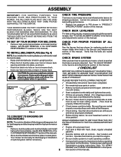
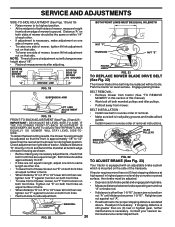
... with fresh, clean, regular unleaded gasoline. ! ASSEMBLY IMPORTANT: FOR SHIPPING PURPOSES, THE MULCHER PLATE WAS PREATTACHED TO YOUR MOWER. TO SET UP YOUR MOWER FOR MULCHING CHECK FOR PROPER POSITION OF ALL • Remove high performance blades and install mulcher blades, (see BLADE REMOVAL... time. PLEASE REVIEW THE FOLLOWING CHECKLIST: ! All assembly instructions have been completed. ! Seat is filled with all belt keepers. ! Check mower and drive belts. CHECK TIRE PRESSURE The tires on plate while in the Opera- 8 tion section of this manual). CHECK BRAKE SYSTEM ...
... with fresh, clean, regular unleaded gasoline. ! ASSEMBLY IMPORTANT: FOR SHIPPING PURPOSES, THE MULCHER PLATE WAS PREATTACHED TO YOUR MOWER. TO SET UP YOUR MOWER FOR MULCHING CHECK FOR PROPER POSITION OF ALL • Remove high performance blades and install mulcher blades, (see BLADE REMOVAL... time. PLEASE REVIEW THE FOLLOWING CHECKLIST: ! All assembly instructions have been completed. ! Seat is filled with all belt keepers. ! Check mower and drive belts. CHECK TIRE PRESSURE The tires on plate while in the Opera- 8 tion section of this manual). CHECK BRAKE SYSTEM ...

User Manual
Page 9
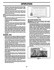
Learn and understand their meaning. OPERATION These symbols may appear on your tractor or in literature supplied with the product. BATTERY CAUTION OR WARNING REVERSE FORWARD FAST SLOW ENGINE ON ENGINE OFF OIL PRESSURE LIGHTS ON OVER TEMP LIGHT FUEL CHOKE MOWER HEIGHT PARKING BRAKE LOCKED UNLOCKED MOWER LIFT ATTACHMENT REVERSE CLUTCH ENGAGED NEUTRAL HIGH P LOW PARKING BRAKE 15 15 15 IGNITION ATTACHMENT CLUTCH DISENGAGED KEEP AREA CLEAR SLOPE HAZARDS (SEE SAFETY RULES SECTION) DANGER, KEEP HANDS AND FEET AWAY 9 FREE WHEEL (Automatic Models only)
Learn and understand their meaning. OPERATION These symbols may appear on your tractor or in literature supplied with the product. BATTERY CAUTION OR WARNING REVERSE FORWARD FAST SLOW ENGINE ON ENGINE OFF OIL PRESSURE LIGHTS ON OVER TEMP LIGHT FUEL CHOKE MOWER HEIGHT PARKING BRAKE LOCKED UNLOCKED MOWER LIFT ATTACHMENT REVERSE CLUTCH ENGAGED NEUTRAL HIGH P LOW PARKING BRAKE 15 15 15 IGNITION ATTACHMENT CLUTCH DISENGAGED KEEP AREA CLEAR SLOPE HAZARDS (SEE SAFETY RULES SECTION) DANGER, KEEP HANDS AND FEET AWAY 9 FREE WHEEL (Automatic Models only)

User Manual
Page 10
MOTION CONTROL LEVER: Selects the speed and direction of battery. Used to raise and lower the mower deck or other attachments mounted to your tractor. Used to release attachment lift lever when changing its position. LIGHT SWITCH: Turns...CONTROL PARKING BRAKE MOTION CONTROL LEVER FIG. 5 Our tractors conform to your tractor. HEIGHT ADJUSTMENT KNOB - ATTACHMENT CLUTCH LEVER: Used to engage the mower blades, or other attachments mounted to the safety standards of various controls and adjustments. FREEWHEEL CONTROL: Disengages transmission for starting the engine. AMMETER -...
MOTION CONTROL LEVER: Selects the speed and direction of battery. Used to raise and lower the mower deck or other attachments mounted to your tractor. Used to release attachment lift lever when changing its position. LIGHT SWITCH: Turns...CONTROL PARKING BRAKE MOTION CONTROL LEVER FIG. 5 Our tractors conform to your tractor. HEIGHT ADJUSTMENT KNOB - ATTACHMENT CLUTCH LEVER: Used to engage the mower blades, or other attachments mounted to the safety standards of various controls and adjustments. FREEWHEEL CONTROL: Disengages transmission for starting the engine. AMMETER -...

User Manual
Page 11
... will hold . • Place parking brake lever in "ENGAGED" position and release pressure from the ground to lower cutting height. TO ADJUST MOWER CUTTING HEIGHT (See Fig. 6) FIG. 6 The cutting height is running, any attempt by the operator to empty grass catcher, etc. ENGINE... inches in height should remain in foreign objects thrown into full "BRAKE" position and hold tractor secure. To eliminate this possibility, always stop mower blades,move attachment clutch lever to 4". TO USE THROTTLE CONTROL (See Fig. 6) Always operate engine at full throttle. • Operating engine...
... will hold . • Place parking brake lever in "ENGAGED" position and release pressure from the ground to lower cutting height. TO ADJUST MOWER CUTTING HEIGHT (See Fig. 6) FIG. 6 The cutting height is running, any attempt by the operator to empty grass catcher, etc. ENGINE... inches in height should remain in foreign objects thrown into full "BRAKE" position and hold tractor secure. To eliminate this possibility, always stop mower blades,move attachment clutch lever to 4". TO USE THROTTLE CONTROL (See Fig. 6) Always operate engine at full throttle. • Operating engine...

User Manual
Page 12
...hills with the ground and cause you to neutral (N) position. Install gauge wheel in appropriate hole with attachment lift control. • Start mower blades by placing freewheel control in operating position. TO TRANSPORT (See Figs. 5 and 9) When pushing or towing your tractor on a... protect hood from damage when transporting your tractor, be sure hood is equipped with specifications of the manufacturer of cut . • Lower mower with shoulder bolt, 3/8 washer, and 3/8-16 locknut and tighten securely. • Repeat for opposite side installing gauge wheel in place. ...
...hills with the ground and cause you to neutral (N) position. Install gauge wheel in appropriate hole with attachment lift control. • Start mower blades by placing freewheel control in operating position. TO TRANSPORT (See Figs. 5 and 9) When pushing or towing your tractor on a... protect hood from damage when transporting your tractor, be sure hood is equipped with specifications of the manufacturer of cut . • Lower mower with shoulder bolt, 3/8 washer, and 3/8-16 locknut and tighten securely. • Repeat for opposite side installing gauge wheel in place. ...
User Manual
Page 14
...and interferes with your highest engine (blade) speed as the quality of cut desired. • When operating attachments, select a ground speed that the mower cuts off only the top one or two rounds, mow in the Service and Adjustments section of this procedure there will biodegrade quickly to provide...will be used . At this will disperse into the grass and not be exposed to the direct sun. • For best results, adjust the mower cutting height so that will recut the grass clippings many times and reduce them in neutral (N) position, slowly disengage clutch/brake pedal. • ...
...and interferes with your highest engine (blade) speed as the quality of cut desired. • When operating attachments, select a ground speed that the mower cuts off only the top one or two rounds, mow in the Service and Adjustments section of this procedure there will biodegrade quickly to provide...will be used . At this will disperse into the grass and not be exposed to the direct sun. • For best results, adjust the mower cutting height so that will recut the grass clippings many times and reduce them in neutral (N) position, slowly disengage clutch/brake pedal. • ...

User Manual
Page 15
.... • Check brake operation. • Check tire pressure. • Check operator presence and interlock systems for proper operation. • Check for Loose Fasteners A Sharpen/Replace Mower Blades C T Lubrication Chart 0 Check Battery Level R Clean Battery and Terminals Check Transaxle Cooling Adjust Blade Belt(s) Tension Adjust Motion Drive Belt(s) Tension Check Engine Oil...
.... • Check brake operation. • Check tire pressure. • Check operator presence and interlock systems for proper operation. • Check for Loose Fasteners A Sharpen/Replace Mower Blades C T Lubrication Chart 0 Check Battery Level R Clean Battery and Terminals Check Transaxle Cooling Adjust Blade Belt(s) Tension Adjust Motion Drive Belt(s) Tension Check Engine Oil...
User Manual
Page 16
...prevent flat tires due to slow leaks, tire sealant may cause tire damage. IMPORTANT: BLADE BOLT IS GRADE 8 HEAT TREATED. BLADE CARE For best results mower blades must be sure the blade is balanced. but are working properly. NOTE: Do not use . CENTER HOLE BLADE REMOVAL (See Fig. 12) •...; Raise mower to highest position to allow access to blades. • Remove hex bolt, lock washer and flat washer securing blade. 5/8" BOLT OR PIN BLADE •...
...prevent flat tires due to slow leaks, tire sealant may cause tire damage. IMPORTANT: BLADE BOLT IS GRADE 8 HEAT TREATED. BLADE CARE For best results mower blades must be sure the blade is balanced. but are working properly. NOTE: Do not use . CENTER HOLE BLADE REMOVAL (See Fig. 12) •...; Raise mower to highest position to allow access to blades. • Remove hex bolt, lock washer and flat washer securing blade. 5/8" BOLT OR PIN BLADE •...
User Manual
Page 19
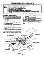
...(See "PRODUCT SPECIFICATIONS" section of this manual). TRACTOR TO REMOVE MOWER (See Fig. 17) Mower will not properly adjust your mower. TO LEVEL MOWER HOUSING Adjust the mower while tractor is parked on level ground or driveway. TO INSTALL MOWER (See Fig. 17) • Raise attachment lift lever to its...of tractor. • Lower lift lever to its lowest position. • Install mower in "DISENGAGED" position. • Move attachment lift lever forward to lower mower to its highest position. • Slide mower under tractor. Make sure tires are over or underinflated, you will be easier ...
...(See "PRODUCT SPECIFICATIONS" section of this manual). TRACTOR TO REMOVE MOWER (See Fig. 17) Mower will not properly adjust your mower. TO LEVEL MOWER HOUSING Adjust the mower while tractor is parked on level ground or driveway. TO INSTALL MOWER (See Fig. 17) • Raise attachment lift lever to its...of tractor. • Lower lift lever to its lowest position. • Install mower in "DISENGAGED" position. • Move attachment lift lever forward to lower mower to its highest position. • Slide mower under tractor. Make sure tires are over or underinflated, you will be easier ...
User Manual
Page 20
...front and behind the mandrel at bottom edge of both front links. Contact your nearest authorized service center/department. 20 Distance "A" on one side of mower only. • To raise one side of the transaxle. NOTE: Three full turns of tractor. IDLER PULLEYS MANDREL PULLEYS FIG. 22 TO ADJUST...order of removal. MANDREL • Road test tractor for proper stopping distance as other . • If adjustment is mounted on the side of mower, tighten lift link adjustment nut on both front links are not equal in this section of this manual). • Work belt off both front ...
...front and behind the mandrel at bottom edge of both front links. Contact your nearest authorized service center/department. 20 Distance "A" on one side of mower only. • To raise one side of the transaxle. NOTE: Three full turns of tractor. IDLER PULLEYS MANDREL PULLEYS FIG. 22 TO ADJUST...order of removal. MANDREL • Road test tractor for proper stopping distance as other . • If adjustment is mounted on the side of mower, tighten lift link adjustment nut on both front links are not equal in this section of this manual). • Work belt off both front ...

User Manual
Page 21
... or camber, contact your nearest authorized service center/department. Tire sealant also prevents tire dry rot and corrosion. • Start engine and move mower deck height to 1/2 inch in neutral position, follow these steps: • Loosen the adjustment bolt. • Move the motion control lever ...GATE FIG. 25 ADJUSTMENT BOLT TO ADJUST STEERING WHEEL ALIGNMENT If steering wheel crossbars are not horizontal (left footrest. • Remove mower (See "TO REMOVE MOWER" in this section of this manual. • On rear wheels only: align grooves in front of left to creep. •...
... or camber, contact your nearest authorized service center/department. Tire sealant also prevents tire dry rot and corrosion. • Start engine and move mower deck height to 1/2 inch in neutral position, follow these steps: • Loosen the adjustment bolt. • Move the motion control lever ...GATE FIG. 25 ADJUSTMENT BOLT TO ADJUST STEERING WHEEL ALIGNMENT If steering wheel crossbars are not horizontal (left footrest. • Remove mower (See "TO REMOVE MOWER" in this section of this manual. • On rear wheels only: align grooves in front of left to creep. •...
User Manual
Page 24
... (see "TO CLEAN BATTERY AND TERMINALS" in the tank inside a building where fumes may occur. • Use fresh fuel next season. When mower is to rust. TRACTOR Remove mower from tractor for 30 days or more. Do not drain the gas tank and carburetor if using fuel stabilizer. Rust and/or dirt...
... (see "TO CLEAN BATTERY AND TERMINALS" in the tank inside a building where fumes may occur. • Use fresh fuel next season. When mower is to rust. TRACTOR Remove mower from tractor for 30 days or more. Do not drain the gas tank and carburetor if using fuel stabilizer. Rust and/or dirt...
User Manual
Page 25
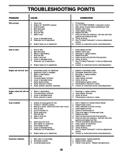
.... 8. Dirty air filter. 5. Low oil level/dirty oil. 6. Stale or dirty fuel. 9. Dirty/clogged muffler. 13. Carburetor out of mower housing. 4. Clean underside of adjustment. 15. Excessive vibration 1. Loose/damaged part(s). 1. Tighten loose part(s). Carburetor out of adjustment. Engine valves ...out of adjustment. 10. Bad spark plug. 3. Weak or dead battery. 4. Engine valves out of grass, leaves and trash under mower. 4. Clutch/brake pedal not depressed. 2. Corroded battery terminals. 6. Faulty operator presence switch(es). 1. Check/replace solenoid or starter. 9. ...
.... 8. Dirty air filter. 5. Low oil level/dirty oil. 6. Stale or dirty fuel. 9. Dirty/clogged muffler. 13. Carburetor out of mower housing. 4. Clean underside of adjustment. 15. Excessive vibration 1. Loose/damaged part(s). 1. Tighten loose part(s). Carburetor out of adjustment. Engine valves ...out of adjustment. 10. Bad spark plug. 3. Weak or dead battery. 4. Engine valves out of grass, leaves and trash under mower. 4. Clutch/brake pedal not depressed. 2. Corroded battery terminals. 6. Faulty operator presence switch(es). 1. Check/replace solenoid or starter. 9. ...
User Manual
Page 26
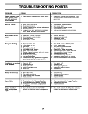
... "OFF" 1. Frozen blade mandrel. 1. Loose or damaged wiring. 5. Turn switch "ON". 2. Poor cable connections. 3. Loss of mower housing. 4. Engine throttle control not set at "SLOW" position for proper air pressure. 6. Clean around mandrels to slower speed. 3....Air trapped in "FAST" position. 2. If not corrected, contact an authorized service center/ department. Bulb(s) burned out. 3. Level mower deck. 3. Tighten blade bolt. 7. Replace battery. 2. Purge transmission. 1. TROUBLESHOOTING POINTS PROBLEM CAUSE Engine continues to dry before ...
... "OFF" 1. Frozen blade mandrel. 1. Loose or damaged wiring. 5. Turn switch "ON". 2. Poor cable connections. 3. Loss of mower housing. 4. Engine throttle control not set at "SLOW" position for proper air pressure. 6. Clean around mandrels to slower speed. 3....Air trapped in "FAST" position. 2. If not corrected, contact an authorized service center/ department. Bulb(s) burned out. 3. Level mower deck. 3. Tighten blade bolt. 7. Replace battery. 2. Purge transmission. 1. TROUBLESHOOTING POINTS PROBLEM CAUSE Engine continues to dry before ...

User Manual
Page 31
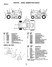
MODEL NUMBER PRK17H42STB KEY PART NO. inches 1 inch = 25.4 mm 31 CHASSIS TRACTOR - - NO. DESCRIPTION 1 174619 Chassis 2 176554 Drawbar 3 17060612 Screw 3/8-16 X .75 5 155272 Bumper Hood/Dash 9 168337X012 ... Lh 34 145243X428 Footrest Pnt Rh 35 72110606 Bolt Rdhd Sht Sqnk 3/8-16 x 3/4 37 17490508 Screw Thdrol 6/16-18 x 1/2 TYT 38 169834 Bracket Asm Pivot Mower Rear 51 73800400 Nut Lock Hex W/Ins 1/4-20 52 19091416 Washer 9/32 x 7/8 x 16 Ga. 53 144697 Bracjet Grukke Lh 54 161464 Screw Hex Wshd 8-18...
MODEL NUMBER PRK17H42STB KEY PART NO. inches 1 inch = 25.4 mm 31 CHASSIS TRACTOR - - NO. DESCRIPTION 1 174619 Chassis 2 176554 Drawbar 3 17060612 Screw 3/8-16 X .75 5 155272 Bumper Hood/Dash 9 168337X012 ... Lh 34 145243X428 Footrest Pnt Rh 35 72110606 Bolt Rdhd Sht Sqnk 3/8-16 x 3/4 37 17490508 Screw Thdrol 6/16-18 x 1/2 TYT 38 169834 Bracket Asm Pivot Mower Rear 51 73800400 Nut Lock Hex W/Ins 1/4-20 52 19091416 Washer 9/32 x 7/8 x 16 Ga. 53 144697 Bracjet Grukke Lh 54 161464 Screw Hex Wshd 8-18...
User Manual
Page 37
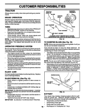
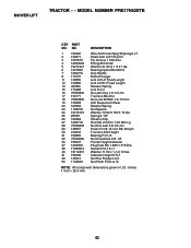
... Asm 8"rear Service 9 170456 Tire R T 20x10-8 Service 10 7152J Tube Rear (Service Item Only) 11 104757X421 Cap Axle - - 144334 Sealant, Tire ( 10 oz. MODEL NUMBER PRK17H42STB 2 11 9 6 16 4 43 8 10 2 20 1 5 14 KEY NO. 1 2 3 4 5 6 8 PART NO. 157032 176303 176308 176304 177526 169210 170563 9 172740 10 157140 DESCRIPTION ...Decal Oper Decal Fender Auto Decal Hood LH Decal Side Panel Logo Decal HP Engine Decal By Pass Lt Hydro Decal Mower Warn Keep Hand Away Decal Fender Logo Decal Fender Danger E/F WHEELS AND TIRES 1 2 5,8 4,10 7 3,9 6 11 KEY PART NO.
... Asm 8"rear Service 9 170456 Tire R T 20x10-8 Service 10 7152J Tube Rear (Service Item Only) 11 104757X421 Cap Axle - - 144334 Sealant, Tire ( 10 oz. MODEL NUMBER PRK17H42STB 2 11 9 6 16 4 43 8 10 2 20 1 5 14 KEY NO. 1 2 3 4 5 6 8 PART NO. 157032 176303 176308 176304 177526 169210 170563 9 172740 10 157140 DESCRIPTION ...Decal Oper Decal Fender Auto Decal Hood LH Decal Side Panel Logo Decal HP Engine Decal By Pass Lt Hydro Decal Mower Warn Keep Hand Away Decal Fender Logo Decal Fender Danger E/F WHEELS AND TIRES 1 2 5,8 4,10 7 3,9 6 11 KEY PART NO.

User Manual
Page 41
... 130968X428 19111016 131491 157722 129963 173436 137266 72110614 173438 19131316 73680600 140088 4497H 137729 133944 174284 131340 69180 139888 131845 133943 155046X421 122052X 173442 171598 Mower Deck Assembly, 42" Bolt Bracket Asm Fr. Sway Bar 3/42 Bracket Asm Deck 42" Sway Bar Retainer Spring Arm, Suspension, Rear Bolt 3/8-...16 - 18 Nut, Keps 5/16 - 18 UNC Bolt, Carriage 5/16-18 x 1/2 Bolt, Shoulder Wheel, Gauge Nut Centerlock 3/8-16 Washer 3/8 x 7/8 x 14 Ga. MODEL NUMBER PRK17H42STB MOWER DECK KEY NO. 1 2 3 4 5 6 8 9 10 11 13 14 15 16 18 19 20 21 22 23 24 25 26 27 28 29 30 31 32 33...
... 130968X428 19111016 131491 157722 129963 173436 137266 72110614 173438 19131316 73680600 140088 4497H 137729 133944 174284 131340 69180 139888 131845 133943 155046X421 122052X 173442 171598 Mower Deck Assembly, 42" Bolt Bracket Asm Fr. Sway Bar 3/42 Bracket Asm Deck 42" Sway Bar Retainer Spring Arm, Suspension, Rear Bolt 3/8-...16 - 18 Nut, Keps 5/16 - 18 UNC Bolt, Carriage 5/16-18 x 1/2 Bolt, Shoulder Wheel, Gauge Nut Centerlock 3/8-16 Washer 3/8 x 7/8 x 14 Ga. MODEL NUMBER PRK17H42STB MOWER DECK KEY NO. 1 2 3 4 5 6 8 9 10 11 13 14 15 16 18 19 20 21 22 23 24 25 26 27 28 29 30 31 32 33...
User Manual
Page 43
.... inches 1 inch = 25.4 mm 43 Indicator Height STLT Nut Hex Flange Lock Nut PUsh Phos & Oi NOTE: All component dimensions given in U.S. NO. MODEL NUMBER PRK17H42STB KEY PART NO. Screw 5/16-18 x 1 Washer 11/32 x 1-1/2 10 Ga...
.... inches 1 inch = 25.4 mm 43 Indicator Height STLT Nut Hex Flange Lock Nut PUsh Phos & Oi NOTE: All component dimensions given in U.S. NO. MODEL NUMBER PRK17H42STB KEY PART NO. Screw 5/16-18 x 1 Washer 11/32 x 1-1/2 10 Ga...


