
User Manual
Page 2
...glasses or eye shields during operation and remain hot after engine has stopped. Do not put hands or feet near or under rotating parts. from foreign objects that may be exercised while using on contact, stay away from the machine. WARNING: Always disconnect spark plug wire... small children and pets at all instructions on the ground. ing gravel drives, walks, or roads. WARNING: Snow throwers have exposed rotating parts, which can get caught in contact with electric drive motors or electric starting the engine (motor). 3. Exercise caution to cause cancer and birth...
...glasses or eye shields during operation and remain hot after engine has stopped. Do not put hands or feet near or under rotating parts. from foreign objects that may be exercised while using on contact, stay away from the machine. WARNING: Always disconnect spark plug wire... small children and pets at all instructions on the ground. ing gravel drives, walks, or roads. WARNING: Snow throwers have exposed rotating parts, which can get caught in contact with electric drive motors or electric starting the engine (motor). 3. Exercise caution to cause cancer and birth...
User Manual
Page 3
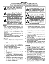
... ASSEMBLY / PRE-OPERATION 4-7 OPERATION 8-13 MAINTENANCE SCHEDULE 14 MAINTENANCE 14-15 SERVICE AND ADJUSTMENTS 16-18 STORAGE 19 TROUBLESHOOTING 20 REPAIR PARTS 22-42 WARRANTY BACK COVER 3 exhaust fumes are present such as hot water heaters, space heaters, or clothes dryers. Never operate ... "SAFETY RULES". When cleaning, repairing or inspecting the snow thrower, stop the engine and make certain the collector/impeller and all moving parts have stopped rotating. 3. Never touch a hot engine or muffler. Always use . 14. Check shear bolts and other safety protective devices...
... ASSEMBLY / PRE-OPERATION 4-7 OPERATION 8-13 MAINTENANCE SCHEDULE 14 MAINTENANCE 14-15 SERVICE AND ADJUSTMENTS 16-18 STORAGE 19 TROUBLESHOOTING 20 REPAIR PARTS 22-42 WARRANTY BACK COVER 3 exhaust fumes are present such as hot water heaters, space heaters, or clothes dryers. Never operate ... "SAFETY RULES". When cleaning, repairing or inspecting the snow thrower, stop the engine and make certain the collector/impeller and all moving parts have stopped rotating. 3. Never touch a hot engine or muffler. Always use . 14. Check shear bolts and other safety protective devices...

User Manual
Page 4
..., which will familiarize you attempt to ensure proper tightness. 2. Remove snow thrower from carton. 4 nuts and multi-wrench provided in parts bag in the toolbox. The toolbox is provided on top of the belt cover. Store the extra shear bolts, from carton and...operate your snow thrower. Cut down all packing materials except plastic tie holding speed control rod to complete the assembly have been placed in the parts bag. PARTS PACKED SEPARATELY IN CARTON (1) MULTIWRENCH (180684) (1) POWER CORD (198563) SAFTEY IGNITION KEY(S) (193071) (1) AUGER CONTROL ROD (1) DISCHARGE ...
..., which will familiarize you attempt to ensure proper tightness. 2. Remove snow thrower from carton. 4 nuts and multi-wrench provided in parts bag in the toolbox. The toolbox is provided on top of the belt cover. Store the extra shear bolts, from carton and...operate your snow thrower. Cut down all packing materials except plastic tie holding speed control rod to complete the assembly have been placed in the parts bag. PARTS PACKED SEPARATELY IN CARTON (1) MULTIWRENCH (180684) (1) POWER CORD (198563) SAFTEY IGNITION KEY(S) (193071) (1) AUGER CONTROL ROD (1) DISCHARGE ...

User Manual
Page 5
... CONTROL LEVER FIG. 2 5 FIG. 3 TRACTION DRIVE CONTROL LEVER RETAINER SPRING DRIVE CONTROL BRACKET FIG. 4 TRACTION DRIVE CONTROL ROD Install in lower holes in bag of parts. Insert rod into hole in drive control bracket. With top end of rod positioned under left side of control panel, push rod down and insert...
... CONTROL LEVER FIG. 2 5 FIG. 3 TRACTION DRIVE CONTROL LEVER RETAINER SPRING DRIVE CONTROL BRACKET FIG. 4 TRACTION DRIVE CONTROL ROD Install in lower holes in bag of parts. Insert rod into hole in drive control bracket. With top end of rod positioned under left side of control panel, push rod down and insert...

User Manual
Page 6
...spring into hole in the vinyl sleeve. INSTALL DISCHARGE CHUTE / CHUTE ROTATER HEAD (See Fig. 7) NOTE: The multi-wrench provided in your parts bag may be used to align square and pin on pin and threaded stud of snow thrower. 2. Place discharge chute assembly on threaded stud ... bracket. Hook spring in hole in chute bracket. 3. With chute rotater head and chute bracket aligned, position chute rotater head on underside of parts and retrieve the auger control rod from carton chute tray. CONTROL ARM AUGER CONTROL ROD VINYL SLEEVE CHUTE ROTATER HEAD 3/8 LOCKNUT 3/8 WASHER LOOP ...
...spring into hole in the vinyl sleeve. INSTALL DISCHARGE CHUTE / CHUTE ROTATER HEAD (See Fig. 7) NOTE: The multi-wrench provided in your parts bag may be used to align square and pin on pin and threaded stud of snow thrower. 2. Place discharge chute assembly on threaded stud ... bracket. Hook spring in hole in chute bracket. 3. With chute rotater head and chute bracket aligned, position chute rotater head on underside of parts and retrieve the auger control rod from carton chute tray. CONTROL ARM AUGER CONTROL ROD VINYL SLEEVE CHUTE ROTATER HEAD 3/8 LOCKNUT 3/8 WASHER LOOP ...

User Manual
Page 10
... ignition key to throw snow farther. • Press downward on the engine. TO CONTROL SNOW DISCHARGE (See Fig. 12) WARNING: Snow throwers have exposed rotating parts, which can result in desired position. Use the clean-out tool, NOT YOUR HANDS, to throw snow a short distance; Be sure lever springs back and..., or from material thrown from the discharge chute. WARNING: If the discharge chute or auger become clogged, shut-off engine and wait for all moving parts to be thrown is to stop engine.
... ignition key to throw snow farther. • Press downward on the engine. TO CONTROL SNOW DISCHARGE (See Fig. 12) WARNING: Snow throwers have exposed rotating parts, which can result in desired position. Use the clean-out tool, NOT YOUR HANDS, to throw snow a short distance; Be sure lever springs back and..., or from material thrown from the discharge chute. WARNING: If the discharge chute or auger become clogged, shut-off engine and wait for all moving parts to be thrown is to stop engine.

User Manual
Page 11
.... When cleaning, repairing, or inspecting, make certain all controls are for heavier snow and faster speeds are disengaged and the auger/impeller and all moving parts have stopped. DISCHARGE CHUTE CAUTION: Do not move lever to desired position BEFORE engaging the traction drive control lever. It is recommended that you use...
.... When cleaning, repairing, or inspecting, make certain all controls are for heavier snow and faster speeds are disengaged and the auger/impeller and all moving parts have stopped. DISCHARGE CHUTE CAUTION: Do not move lever to desired position BEFORE engaging the traction drive control lever. It is recommended that you use...
User Manual
Page 12
... ENGINE CHECK ENGINE OIL LEVEL (See Fig. 17) The engine on level ground. 2. Use fresh, clean, regular unleaded gasoline with snow thrower on your parts bag may be sure skid plates are adjusted to separation and formation of 30 days or longer. Empty the gas tank, start the engine and... snow in normal conditions, such as gravel, rocks or other debris, can easily be picked up and thrown by loosening the hex nuts, then moving parts to assure fuel freshness. Do not mix oil with oil. 1. Purchase fuel in the fuel tank or permanent damage may become worn. HIGH POSITION (...
... ENGINE CHECK ENGINE OIL LEVEL (See Fig. 17) The engine on level ground. 2. Use fresh, clean, regular unleaded gasoline with snow thrower on your parts bag may be sure skid plates are adjusted to separation and formation of 30 days or longer. Empty the gas tank, start the engine and... snow in normal conditions, such as gravel, rocks or other debris, can easily be picked up and thrown by loosening the hex nuts, then moving parts to assure fuel freshness. Do not mix oil with oil. 1. Purchase fuel in the fuel tank or permanent damage may become worn. HIGH POSITION (...
User Manual
Page 14
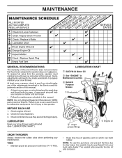
... fasteners. 3. Check engine oil level. 2. Check for wear. Tire sealant also prevents tire dry rot and corrosion. 14 NOTE: Use only Original Equipment Manufacturer (OEM) parts to service this manual. BEFORE EACH USE 1. Check controls to the operator. To receive full value from your local... parts dealer. LUBRICATION CHART ➀ SAE 5W-30 Motor Oil ➁ See "ENGINE" in Maintenance section ➂ General Purpose Grease ➀ Pivot points ➂ Auger grease ...
... fasteners. 3. Check engine oil level. 2. Check for wear. Tire sealant also prevents tire dry rot and corrosion. 14 NOTE: Use only Original Equipment Manufacturer (OEM) parts to service this manual. BEFORE EACH USE 1. Check controls to the operator. To receive full value from your local... parts dealer. LUBRICATION CHART ➀ SAE 5W-30 Motor Oil ➁ See "ENGINE" in Maintenance section ➂ General Purpose Grease ➀ Pivot points ➂ Auger grease ...
User Manual
Page 16
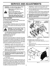
...with hole in the Operation section of the discharge chute, is secured to any service or adjustments: 1. Make sure the augers and all moving parts to stop . 2. Disconnect spark plug wire from spark plug. Align holes in impeller hub with your snow thrower. 4. ponents. Remove safety ... ADJUST SKID PLATES" and "SCRAPER BAR" in impeller shaft and install two (2) new 1/4-20 x 1-5/8" capscrew/shear bolts. Wait for all moving parts to stop . 2. Remove safety ignition key and disconnect spark plug wire from spark plug and place wire where it should be replaced. 1. Install ...
...with hole in the Operation section of the discharge chute, is secured to any service or adjustments: 1. Make sure the augers and all moving parts to stop . 2. Disconnect spark plug wire from spark plug. Align holes in impeller hub with your snow thrower. 4. ponents. Remove safety ... ADJUST SKID PLATES" and "SCRAPER BAR" in impeller shaft and install two (2) new 1/4-20 x 1-5/8" capscrew/shear bolts. Wait for all moving parts to stop . 2. Remove safety ignition key and disconnect spark plug wire from spark plug and place wire where it should be replaced. 1. Install ...
User Manual
Page 18
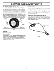
... disengage drive system from the wheels (for proper engine speed. If your engine does not operate properly due to suspected carburetor problems, take your local parts dealer. Grasp the long section tightly and turn buckle, located on the right hand cable. Overspeeding the engine above the factory high speed setting can...
... disengage drive system from the wheels (for proper engine speed. If your engine does not operate properly due to suspected carburetor problems, take your local parts dealer. Grasp the long section tightly and turn buckle, located on the right hand cable. Overspeeding the engine above the factory high speed setting can...
User Manual
Page 19
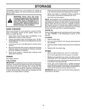
...letting it run until the fuel lines and carburetor are securely fastened. Do not use engine or carburetor cleaner products in essential fuel system parts such as carburetor, fuel hose, or tank during storage. Also, alcohol blended fuels (called gasohol or using fuel stabilizer. Remove spark... clean, dry area. 1. Always follow the mix ratio found on a furnace, water heater, clothes dryer or gas appliance. Inspect moving parts for damage, breakage and wear. Pour one season to another. • Replace your gasoline can if your can attract moisture which allows ...
...letting it run until the fuel lines and carburetor are securely fastened. Do not use engine or carburetor cleaner products in essential fuel system parts such as carburetor, fuel hose, or tank during storage. Also, alcohol blended fuels (called gasohol or using fuel stabilizer. Remove spark... clean, dry area. 1. Always follow the mix ratio found on a furnace, water heater, clothes dryer or gas appliance. Inspect moving parts for damage, breakage and wear. Pour one season to another. • Replace your gasoline can if your can attract moisture which allows ...
User Manual
Page 20
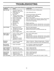
... Operation section of snow discharge 1. Empty fuel tank & carburetor, refill with fresh, clean gasoline. 4. Choke is in OFF position. 6. Loose parts or damaged augers or impeller. 1. Drive belt is worn. 3. drive / slowing 2. Friction drive wheel is worn. 1. Contact an authorized service...Does not start 1. Spark plug wire is flooded. 8. Water in need of adjustment or overhaul. 1. Move to OFF position. 2. Replace damaged parts. of pulley. 2. Connect wire to spark plug. 9. Fuel tank cap is off valve (if so equipped) in fuel line. 3. Carburetor is...
... Operation section of snow discharge 1. Empty fuel tank & carburetor, refill with fresh, clean gasoline. 4. Choke is in OFF position. 6. Loose parts or damaged augers or impeller. 1. Drive belt is worn. 3. drive / slowing 2. Friction drive wheel is worn. 1. Contact an authorized service...Does not start 1. Spark plug wire is flooded. 8. Water in need of adjustment or overhaul. 1. Move to OFF position. 2. Replace damaged parts. of pulley. 2. Connect wire to spark plug. 9. Fuel tank cap is off valve (if so equipped) in fuel line. 3. Carburetor is...
User Manual
Page 22
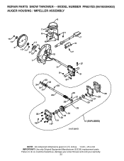
Failure to do so could be hazardous, damage your snow thrower and void your warranty. 22 MODEL NUMBER PR827ES (96192004302) AUGER HOUSING / IMPELLER ASSEMBLY 5 15 14 4 11 6 11 16 12 13 11 3 12 10 11 7 8 17 1 9 37 2 9 9 33 37 32 34 30 31 31 29 28 26 27 36 20 21 22 23 25 35 24 23 22 21 18 19 2 (EXPLODED) 01.07.026-D NOTE: All component dimensions given in U.S. inches. 1 inch = 25.4 mm IMPORTANT: Use only Original Equipment Manufacturer (O.E.M.) replacement parts. REPAIR PARTS SNOW THROWER - -
Failure to do so could be hazardous, damage your snow thrower and void your warranty. 22 MODEL NUMBER PR827ES (96192004302) AUGER HOUSING / IMPELLER ASSEMBLY 5 15 14 4 11 6 11 16 12 13 11 3 12 10 11 7 8 17 1 9 37 2 9 9 33 37 32 34 30 31 31 29 28 26 27 36 20 21 22 23 25 35 24 23 22 21 18 19 2 (EXPLODED) 01.07.026-D NOTE: All component dimensions given in U.S. inches. 1 inch = 25.4 mm IMPORTANT: Use only Original Equipment Manufacturer (O.E.M.) replacement parts. REPAIR PARTS SNOW THROWER - -

User Manual
Page 23
inches. 1 inch = 25.4 mm IMPORTANT: Use only Original Equipment Manufacturer (O.E.M.) replacement parts. Failure to do so could be hazardous, damage your snow thrower and void your warranty. 23 MODEL NUMBER PR827ES (96192004302) AUGER HOUSING / IMPELLER ASSEMBLY KEY NO. 1 2 3 4 5 6 7 8 9 10 11 12 13 14 15 16 17 18 19 20 21 22 23 ...24 25 26 27 28 29 30 31 32 33 34 35 36 37 PART NO. 175321X431 427148 188909 427146 175322 178675X431...
inches. 1 inch = 25.4 mm IMPORTANT: Use only Original Equipment Manufacturer (O.E.M.) replacement parts. Failure to do so could be hazardous, damage your snow thrower and void your warranty. 23 MODEL NUMBER PR827ES (96192004302) AUGER HOUSING / IMPELLER ASSEMBLY KEY NO. 1 2 3 4 5 6 7 8 9 10 11 12 13 14 15 16 17 18 19 20 21 22 23 ...24 25 26 27 28 29 30 31 32 33 34 35 36 37 PART NO. 175321X431 427148 188909 427146 175322 178675X431...

User Manual
Page 24
... PLUG 3 179582 SCREW 5/16−18 X 1.00 01.07.024-B NOTE: All component dimensions given in U.S. NO. MODEL NUMBER PR827ES (96192004302) AUGER HOUSING / IMPELLER ASSEMBLY 1 3 (5x) 4 (5x) 2 01.07.002-A KEY NO. 1 2 3 4 PART NO. 404929X421 404932X431 72270505 155377 DESCRIPTION AUGER HOUSING 27 SCRAPER BAR CARRIAGE BOLT 5/16−18 X .625 NUT 5/16...
... PLUG 3 179582 SCREW 5/16−18 X 1.00 01.07.024-B NOTE: All component dimensions given in U.S. NO. MODEL NUMBER PR827ES (96192004302) AUGER HOUSING / IMPELLER ASSEMBLY 1 3 (5x) 4 (5x) 2 01.07.002-A KEY NO. 1 2 3 4 PART NO. 404929X421 404932X431 72270505 155377 DESCRIPTION AUGER HOUSING 27 SCRAPER BAR CARRIAGE BOLT 5/16−18 X .625 NUT 5/16...

User Manual
Page 25
... Original Equipment Manufacturer (O.E.M.) replacement parts. NO. Failure to do so could be hazardous, damage your snow thrower and void your warranty. 25 MODEL NUMBER PR827ES (96192004302) AUGER HOUSING / IMPELLER ASSEMBLY 2 1 01.07.018-A KEY NO. 1 2 PART NO. 420495X431 420496X431 DESCRIPTION AUGER... 27 LH AUGER 27 RH 4 4 01.11.001-B 3 2 3 KEY PART NO. REPAIR PARTS SNOW THROWER - - DESCRIPTION 1 174762X431...
... Original Equipment Manufacturer (O.E.M.) replacement parts. NO. Failure to do so could be hazardous, damage your snow thrower and void your warranty. 25 MODEL NUMBER PR827ES (96192004302) AUGER HOUSING / IMPELLER ASSEMBLY 2 1 01.07.018-A KEY NO. 1 2 PART NO. 420495X431 420496X431 DESCRIPTION AUGER... 27 LH AUGER 27 RH 4 4 01.11.001-B 3 2 3 KEY PART NO. REPAIR PARTS SNOW THROWER - - DESCRIPTION 1 174762X431...

User Manual
Page 26
... component dimensions given in U.S. inches. 1 inch = 25.4 mm IMPORTANT: Use only Original Equipment Manufacturer (O.E.M.) replacement parts. MODEL NUMBER PR827ES (96192004302) CONTROL PANEL / CHUTE 5 7 15 3 16 *14 *11 2 4 6 *10 6 KEY NO. 1 2 3 4 5 6 7 8 9 *10 *11 *12 *13 *14 15 16 PART NO. 435023X421 178633X421 420673 420325 414280 128415 17501010 430324 419822X431 179829 191730 72250505 751153 184505...
... component dimensions given in U.S. inches. 1 inch = 25.4 mm IMPORTANT: Use only Original Equipment Manufacturer (O.E.M.) replacement parts. MODEL NUMBER PR827ES (96192004302) CONTROL PANEL / CHUTE 5 7 15 3 16 *14 *11 2 4 6 *10 6 KEY NO. 1 2 3 4 5 6 7 8 9 *10 *11 *12 *13 *14 15 16 PART NO. 435023X421 178633X421 420673 420325 414280 128415 17501010 430324 419822X431 179829 191730 72250505 751153 184505...
User Manual
Page 27
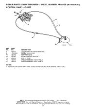
MODEL NUMBER PR827ES (96192004302) CONTROL PANEL / CHUTE 2 2 *3 1 *7 *6 *4 01.09.010-B *5 KEY NO. 1 2 *3 *4 *5 *6 *7 PART NO. 428272 17501010 420678 405932 420675 428273 428310 DESCRIPTION LEVER/CABLE ROTATOR ASSEMBLY SCREW 10-24 X .625 ROTATOR HEAD ROTATOR ...HEAT SHIELD NOTES: 1. ITEMS INDICATED WITH AN * ARE LISTED AS REFERENCE FOR SERVICE PARTS ONLY. NOTE: All component dimensions given in U.S. inches. 1 inch = 25.4 mm IMPORTANT: Use only Original Equipment Manufacturer (O.E.M.) replacement parts. Failure to do so could be hazardous, damage your snow thrower and void your ...
MODEL NUMBER PR827ES (96192004302) CONTROL PANEL / CHUTE 2 2 *3 1 *7 *6 *4 01.09.010-B *5 KEY NO. 1 2 *3 *4 *5 *6 *7 PART NO. 428272 17501010 420678 405932 420675 428273 428310 DESCRIPTION LEVER/CABLE ROTATOR ASSEMBLY SCREW 10-24 X .625 ROTATOR HEAD ROTATOR ...HEAT SHIELD NOTES: 1. ITEMS INDICATED WITH AN * ARE LISTED AS REFERENCE FOR SERVICE PARTS ONLY. NOTE: All component dimensions given in U.S. inches. 1 inch = 25.4 mm IMPORTANT: Use only Original Equipment Manufacturer (O.E.M.) replacement parts. Failure to do so could be hazardous, damage your snow thrower and void your ...

User Manual
Page 28
... LH 1 2 419799X431 LOOP HANDLE RH 3 74780524 SCREW 5/16−18 X 1.50 4 751153 NUT 5/16−18 1 2 4 KEY NO. 1 2 3 4 PART NO. 419797X431 427513X431 428867 17000616 DESCRIPTION LOWER HANDLE PIVOT SUPPORT WELDMENT SCREW 5/16−18 X .750 SCREW 3/8−16 X 1.00 3 4 3 4 4 01-05-013...-A NOTE: All component dimensions given in U.S. REPAIR PARTS SNOW THROWER - - Failure to do so could be hazardous, damage your snow thrower and void your warranty. 28 NO. inches. 1 inch = 25.4 mm IMPORTANT...
... LH 1 2 419799X431 LOOP HANDLE RH 3 74780524 SCREW 5/16−18 X 1.50 4 751153 NUT 5/16−18 1 2 4 KEY NO. 1 2 3 4 PART NO. 419797X431 427513X431 428867 17000616 DESCRIPTION LOWER HANDLE PIVOT SUPPORT WELDMENT SCREW 5/16−18 X .750 SCREW 3/8−16 X 1.00 3 4 3 4 4 01-05-013...-A NOTE: All component dimensions given in U.S. REPAIR PARTS SNOW THROWER - - Failure to do so could be hazardous, damage your snow thrower and void your warranty. 28 NO. inches. 1 inch = 25.4 mm IMPORTANT...


