
User Manual
Page 2
.... Preparation 1. Adjust the collector housing height to prevent accidental starting motors. 6. Do not put hands or feet near or under rotating parts. ing gravel drives, walks, or roads. WARNING: This snow thrower is for any adjustments while the engine (motor) is generally a... all persons, particularly small children. 4. WARNING: Always disconnect spark plug wire and place it where it cannot contact plug in moving parts. containers on the machine and in reverse. Exercise caution to vibrate abnormally, stop the engine (motor), remove the wire from the ...
.... Preparation 1. Adjust the collector housing height to prevent accidental starting motors. 6. Do not put hands or feet near or under rotating parts. ing gravel drives, walks, or roads. WARNING: This snow thrower is for any adjustments while the engine (motor) is generally a... all persons, particularly small children. 4. WARNING: Always disconnect spark plug wire and place it where it cannot contact plug in moving parts. containers on the machine and in reverse. Exercise caution to vibrate abnormally, stop the engine (motor), remove the wire from the ...
User Manual
Page 3
When cleaning, repairing or inspecting the snow thrower, stop the engine and make certain the collector/impeller and all moving parts have stopped rotating. 3. Keep children and others away. 11. Do not overload the machine capacity by the manufacturer of...13-14 PRODUCT SPECIFICATIONS 3 SERVICE AND ADJUSTMENTS 15-17 CUSTOMER RESPONSIBILITIES 3 STORAGE 17 ASSEMBLY / PRE-OPERATION 4-7 TROUBLESHOOTING 18 OPERATION 8-12 REPAIR PARTS 20-37 MAINTENANCE SCHEDULE 13 3 WARRANTY BACK COVER Disconnect the spark plug wire and keep a firm hold on slippery surfaces. Exercise extreme ...
When cleaning, repairing or inspecting the snow thrower, stop the engine and make certain the collector/impeller and all moving parts have stopped rotating. 3. Keep children and others away. 11. Do not overload the machine capacity by the manufacturer of...13-14 PRODUCT SPECIFICATIONS 3 SERVICE AND ADJUSTMENTS 15-17 CUSTOMER RESPONSIBILITIES 3 STORAGE 17 ASSEMBLY / PRE-OPERATION 4-7 TROUBLESHOOTING 18 OPERATION 8-12 REPAIR PARTS 20-37 MAINTENANCE SCHEDULE 13 3 WARRANTY BACK COVER Disconnect the spark plug wire and keep a firm hold on slippery surfaces. Exercise extreme ...
User Manual
Page 4
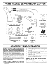
... flat. 3. Remove snow thrower from carton. 4 located on your new snow thrower. Store the extra shear bolts, nuts and multi-wrench provided in parts bag in the toolbox. HOW TO SET UP YOUR SNOW THROWER TOOL BOX (See Fig. 8) REMOVE SNOW THROWER FROM CARTON A toolbox is 1. Your... two (2) screws securing the auger housing to the pallet. 6. Remove the two (2) plastic ties securing the upper handle to the pallet. 4. Remove all parts and hardware you assemble must be tightened securely. To ensure safe and proper operation of the belt cover. Use the correct tools as nuts, washers...
... flat. 3. Remove snow thrower from carton. 4 located on your new snow thrower. Store the extra shear bolts, nuts and multi-wrench provided in parts bag in the toolbox. HOW TO SET UP YOUR SNOW THROWER TOOL BOX (See Fig. 8) REMOVE SNOW THROWER FROM CARTON A toolbox is 1. Your... two (2) screws securing the auger housing to the pallet. 6. Remove the two (2) plastic ties securing the upper handle to the pallet. 4. Remove all parts and hardware you assemble must be tightened securely. To ensure safe and proper operation of the belt cover. Use the correct tools as nuts, washers...

User Manual
Page 5
... CONTROL BRACKET FIG. 4 TRACTION DRIVE CONTROL ROD Install in lower holes in drive control bracket. Secure with loop opening down and insert top end of parts. UNFOLD UPPER HANDLE 1. Use to secure upper handle to the skid plates. Slide rubber sleeve up rod and hook end of spring into hole in...
... CONTROL BRACKET FIG. 4 TRACTION DRIVE CONTROL ROD Install in lower holes in drive control bracket. Secure with loop opening down and insert top end of parts. UNFOLD UPPER HANDLE 1. Use to secure upper handle to the skid plates. Slide rubber sleeve up rod and hook end of spring into hole in...

User Manual
Page 6
... of chute base with loop opening toward front of the spring as shown. 2. If necessary, rotate chute assembly to align square and pin on your parts bag may be used to 14-17 PSI (19-24.5 N-m). Install 3/8 washer and locknut on the end of snow thrower. 2. ASSEMBLY / PRE-OPERATION INSTALL AUGER...
... of chute base with loop opening toward front of the spring as shown. 2. If necessary, rotate chute assembly to align square and pin on your parts bag may be used to 14-17 PSI (19-24.5 N-m). Install 3/8 washer and locknut on the end of snow thrower. 2. ASSEMBLY / PRE-OPERATION INSTALL AUGER...

User Manual
Page 9
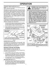
...: Never use . The DIRECTION in which can result in desired position. HOW TO USE YOUR SNOW THROWER Know how to operate all moving parts to stop engine. Use the choke control whenever you are starting a cold engine. We recommend standard safety glasses or a wide vision safety ...the area of operation clear of the chute deflector. TO CONTROL SNOW DISCHARGE (See Figs. 11 & 12) WARNING: Snow throwers have exposed rotating parts, which snow is to be thrown is controlled by the discharge chute control lever. • To change the deflector position, loosen knob, move ...
...: Never use . The DIRECTION in which can result in desired position. HOW TO USE YOUR SNOW THROWER Know how to operate all moving parts to stop engine. Use the choke control whenever you are starting a cold engine. We recommend standard safety glasses or a wide vision safety ...the area of operation clear of the chute deflector. TO CONTROL SNOW DISCHARGE (See Figs. 11 & 12) WARNING: Snow throwers have exposed rotating parts, which snow is to be thrown is controlled by the discharge chute control lever. • To change the deflector position, loosen knob, move ...

User Manual
Page 10
... tool from the handle and adjust the discharge chute direction without interrupting the snow throwing process. When cleaning, repairing, or inspecting, make certain all moving parts have stopped. TO MOVE FORWARD AND BACKWARD (See Fig. 15) SELF-PROPELLING, forward and reverse movement of the snow thrower, is controlled by the auger...
... tool from the handle and adjust the discharge chute direction without interrupting the snow throwing process. When cleaning, repairing, or inspecting, make certain all moving parts have stopped. TO MOVE FORWARD AND BACKWARD (See Fig. 15) SELF-PROPELLING, forward and reverse movement of the snow thrower, is controlled by the auger...
User Manual
Page 11
...has worn almost to assure fuel freshness. 11 WARNING: Wipe off engine and wait for additional information. Check engine oil with snow thrower on your parts bag may be used within 30 days to the edge of the housing, it run until "FULL" mark on each side of acids during storage.... Do not mix oil with a minimum of snow in quantities that can be picked up and thrown by loosening the hex nuts, then moving parts to proper height for a few seconds, remove and read oil level. ON / OFF SWITCH CHOKE CONTROL RECOIL (AUXILIARY) STARTER HANDLE GASOLINE FILLER CAP ENGINE OIL...
...has worn almost to assure fuel freshness. 11 WARNING: Wipe off engine and wait for additional information. Check engine oil with snow thrower on your parts bag may be used within 30 days to the edge of the housing, it run until "FULL" mark on each side of acids during storage.... Do not mix oil with a minimum of snow in quantities that can be picked up and thrown by loosening the hex nuts, then moving parts to proper height for a few seconds, remove and read oil level. ON / OFF SWITCH CHOKE CONTROL RECOIL (AUXILIARY) STARTER HANDLE GASOLINE FILLER CAP ENGINE OIL...

User Manual
Page 12
.... household current. • Be sure your house is not a 120 Volt A.C. DO NOT push the primer. Insert safety ignition key (packed separately in parts bag) into ignition slot until it is ready for a few minutes. Place ON / OFF switch in a safe place. 2. NOTE: Do not use ...power cord from the receptacle first, then from starting engine with both a 120 Volt A.C. COLD START - Insert safety ignition key (packed separately in parts bag) into a three-hole grounded 120 Volt A.C. Engine will help dry off any moisture on 120 Volt A.C. Keep the extra safety ignition key...
.... household current. • Be sure your house is not a 120 Volt A.C. DO NOT push the primer. Insert safety ignition key (packed separately in parts bag) into ignition slot until it is ready for a few minutes. Place ON / OFF switch in a safe place. 2. NOTE: Do not use ...power cord from the receptacle first, then from starting engine with both a 120 Volt A.C. COLD START - Insert safety ignition key (packed separately in parts bag) into a three-hole grounded 120 Volt A.C. Engine will help dry off any moisture on 120 Volt A.C. Keep the extra safety ignition key...

User Manual
Page 13
...8226; Follow the maintenance schedule in the Service and Adjustments section of the adjustments described in this manual. NOTE: Use only Original Equipment Manufacturer (OEM) parts to service this snow thrower does not cover items that have been subjected to do so can harm rubber. Check engine oil level. 2. TIRES &#... Engine oil SNOW THROWER Always observe the safety rules when performing any of this manual. Check controls to the operator. LUBRICATION Keep your local parts dealer. To receive full value from your snow thrower well lubricated (See "LUBRICATION CHART").
...8226; Follow the maintenance schedule in the Service and Adjustments section of the adjustments described in this manual. NOTE: Use only Original Equipment Manufacturer (OEM) parts to service this snow thrower does not cover items that have been subjected to do so can harm rubber. Check engine oil level. 2. TIRES &#... Engine oil SNOW THROWER Always observe the safety rules when performing any of this manual. Check controls to the operator. LUBRICATION Keep your local parts dealer. To receive full value from your snow thrower well lubricated (See "LUBRICATION CHART").

User Manual
Page 15
... (2) new 1/4-20 x 1-5/8" capscrew/shear bolts. Replace belt cover by installing cover and screws and tighten securely. Wait for all moving parts to STOP position. Remove safety ignition key and disconnect spark plug wire from spark plug. Place wire where it cannot come in contact with... break, preventing damage to the impeller shaft with holes in the impeller, the capscrews are secured to frame. 2. Wait for all moving parts have sheared. Align hole in auger hub with plug. Remove safety ignition key. 3. Disconnect spark plug wire from the operator. To replace...
... (2) new 1/4-20 x 1-5/8" capscrew/shear bolts. Replace belt cover by installing cover and screws and tighten securely. Wait for all moving parts to STOP position. Remove safety ignition key and disconnect spark plug wire from spark plug. Place wire where it cannot come in contact with... break, preventing damage to the impeller shaft with holes in the impeller, the capscrews are secured to frame. 2. Wait for all moving parts have sheared. Align hole in auger hub with plug. Remove safety ignition key. 3. Disconnect spark plug wire from the operator. To replace...

User Manual
Page 17
...Engine performance should not be stored for storage at least 10 minutes after adding stabilizer to allow the stabilizer to gasoline in essential fuel system parts such as carburetor, fuel hose, or tank during storage. If you think the engine-governed high speed needs adjusting, contact a qualified ...; Replace your gasoline can damage the fuel IMPORTANT: Never cover snow thrower while engine/ex- system of this manual. 4. Inspect moving parts for pushing or transporting the snow thrower), remove klik pin from axle. Do not use the innermost hole in the Maintenance section of ...
...Engine performance should not be stored for storage at least 10 minutes after adding stabilizer to allow the stabilizer to gasoline in essential fuel system parts such as carburetor, fuel hose, or tank during storage. If you think the engine-governed high speed needs adjusting, contact a qualified ...; Replace your gasoline can damage the fuel IMPORTANT: Never cover snow thrower while engine/ex- system of this manual. 4. Inspect moving parts for pushing or transporting the snow thrower), remove klik pin from axle. Do not use the innermost hole in the Maintenance section of ...
User Manual
Page 18
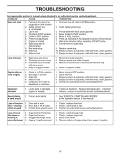
...manual. Fuel tank cap is off valve (if so equipped) in STOP position 5. Reconnect spark plug wire. 2. Stale fuel. 4. Loose parts or damaged augers or impeller. 1. Drive belt is worn. 3. Check / replace auger belt. 3. Replace spark plug. 10. Empty fuel... restarting, DO NOT prime. 8. Water in OFF position. 6. Contact an authorized service centre/department. Tighten all fasteners. Replace damaged parts. Recoil starter is disconnected. 9. See "IF RECOIL STARTER HAS FROZEN" in the Operation section of pulley. 2. Drive belt is covered with...
...manual. Fuel tank cap is off valve (if so equipped) in STOP position 5. Reconnect spark plug wire. 2. Stale fuel. 4. Loose parts or damaged augers or impeller. 1. Drive belt is worn. 3. Check / replace auger belt. 3. Replace spark plug. 10. Empty fuel... restarting, DO NOT prime. 8. Water in OFF position. 6. Contact an authorized service centre/department. Tighten all fasteners. Replace damaged parts. Recoil starter is disconnected. 9. See "IF RECOIL STARTER HAS FROZEN" in the Operation section of pulley. 2. Drive belt is covered with...

User Manual
Page 21
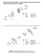
MODEL NUMBER PR5524ESLCT (96192002501) AUGER HOUSING / IMPELLER ASSEMBLY KEY NO. 1 2 3 4 5 6 7 8 9 10 11 12 13 14 15 16 17 18 19 20 21 22 23 24 25 26 27 28 29 30 31 32 33 34 35 36 PART NO. inches. 1 inch = 25.4 mm IMPORTANT: Use only Original Equipment Manufacturer (O.E.M.) replacement parts. Failure to do... SHAFT ROLL PIN THRUST WASHER THRUST BEARING BEARING O−RING SCREW 5/16−18 X .750 GEARBOX COVER LH NOTE: All component dimensions given in U.S. REPAIR PARTS SNOW THROWER - -
MODEL NUMBER PR5524ESLCT (96192002501) AUGER HOUSING / IMPELLER ASSEMBLY KEY NO. 1 2 3 4 5 6 7 8 9 10 11 12 13 14 15 16 17 18 19 20 21 22 23 24 25 26 27 28 29 30 31 32 33 34 35 36 PART NO. inches. 1 inch = 25.4 mm IMPORTANT: Use only Original Equipment Manufacturer (O.E.M.) replacement parts. Failure to do... SHAFT ROLL PIN THRUST WASHER THRUST BEARING BEARING O−RING SCREW 5/16−18 X .750 GEARBOX COVER LH NOTE: All component dimensions given in U.S. REPAIR PARTS SNOW THROWER - -

User Manual
Page 22
..., damage your snow thrower and void your warranty. 22 inches. 1 inch = 25.4 mm IMPORTANT: Use only Original Equipment Manufacturer (O.E.M.) replacement parts. MODEL NUMBER PR5524ESLCT (96192002501) AUGER HOUSING / IMPELLER ASSEMBLY 1 KEY NO. 1 2 3 4 PART NO. 404928X428 404931X479 72270505 155377 DESCRIPTION AUGER HOUSING SCRAPPER BAR CARRIAGE BOLT 5/16−18 X .625 NUT 5/16−18 3 (5x...
..., damage your snow thrower and void your warranty. 22 inches. 1 inch = 25.4 mm IMPORTANT: Use only Original Equipment Manufacturer (O.E.M.) replacement parts. MODEL NUMBER PR5524ESLCT (96192002501) AUGER HOUSING / IMPELLER ASSEMBLY 1 KEY NO. 1 2 3 4 PART NO. 404928X428 404931X479 72270505 155377 DESCRIPTION AUGER HOUSING SCRAPPER BAR CARRIAGE BOLT 5/16−18 X .625 NUT 5/16−18 3 (5x...
User Manual
Page 23
inches. 1 inch = 25.4 mm IMPORTANT: Use only Original Equipment Manufacturer (O.E.M.) replacement parts. DESCRIPTION 1 174762X479 SKID PLATE LH 2 178777X479 SKID PLATE RH 3 72270506 CARRIAGE BOLT 5/16−18 X .75 3 01.11.001-A 1 4 ...Failure to do so could be hazardous, damage your snow thrower and void your warranty. 23 NO. REPAIR PARTS SNOW THROWER - - MODEL NUMBER PR5524ESLCT (96192002501) AUGER HOUSING / IMPELLER ASSEMBLY 2 3 1 1 2 3 01.07.024-B KEY NO. 1 2 3 PART NO. 420478 411939 179582 DESCRIPTION PALIER, TARIÈRE BOUCHON VIS 5/16−18 X 1.00 3 4...
inches. 1 inch = 25.4 mm IMPORTANT: Use only Original Equipment Manufacturer (O.E.M.) replacement parts. DESCRIPTION 1 174762X479 SKID PLATE LH 2 178777X479 SKID PLATE RH 3 72270506 CARRIAGE BOLT 5/16−18 X .75 3 01.11.001-A 1 4 ...Failure to do so could be hazardous, damage your snow thrower and void your warranty. 23 NO. REPAIR PARTS SNOW THROWER - - MODEL NUMBER PR5524ESLCT (96192002501) AUGER HOUSING / IMPELLER ASSEMBLY 2 3 1 1 2 3 01.07.024-B KEY NO. 1 2 3 PART NO. 420478 411939 179582 DESCRIPTION PALIER, TARIÈRE BOUCHON VIS 5/16−18 X 1.00 3 4...

User Manual
Page 24
inches. 1 inch = 25.4 mm IMPORTANT: Use only Original Equipment Manufacturer (O.E.M.) replacement parts. MODEL NUMBER PR5524ESLCT (96192002501) CONTROL PANEL / CHUTE 2 11 3 6 8 6 10 5 9 11 4 11 7 1 01.09.001-A KEY NO. 1 2 3 4 5 6 7 8 9 10 11 PART NO. 404770X428 178633X428 420325 179096X479 189713X479 128415 185600 72270505 191730 155415 179246 DESCRIPTION CHUTE WELDMENT DEFLECTOR WELDMENT DEFLECTOR SEAL STRAP KNOB ... NOTE: All component dimensions given in U.S. Failure to do so could be hazardous, damage your snow thrower and void your warranty. 24 REPAIR PARTS SNOW THROWER - -
inches. 1 inch = 25.4 mm IMPORTANT: Use only Original Equipment Manufacturer (O.E.M.) replacement parts. MODEL NUMBER PR5524ESLCT (96192002501) CONTROL PANEL / CHUTE 2 11 3 6 8 6 10 5 9 11 4 11 7 1 01.09.001-A KEY NO. 1 2 3 4 5 6 7 8 9 10 11 PART NO. 404770X428 178633X428 420325 179096X479 189713X479 128415 185600 72270505 191730 155415 179246 DESCRIPTION CHUTE WELDMENT DEFLECTOR WELDMENT DEFLECTOR SEAL STRAP KNOB ... NOTE: All component dimensions given in U.S. Failure to do so could be hazardous, damage your snow thrower and void your warranty. 24 REPAIR PARTS SNOW THROWER - -

User Manual
Page 25
MODEL NUMBER PR5524ESLCT (96192002501) CONTROL PANEL / CHUTE 2 2 *3 1 *6 KEY NO. 1 2 *3 *4 *5 *6 PART NO. 420337 17501010 420678 420677 420675 420674 *6 DESCRIPTION LEVER/CABLE ROTATOR ASSEMBLY SCREW 10−24 X .625 ROTATOR HEAD ROTATOR PIVOT BRACKET PULLEY PIVOT ... so could be hazardous, damage your snow thrower and void your warranty. 25 inches. 1 inch = 25.4 mm IMPORTANT: Use only Original Equipment Manufacturer (O.E.M.) replacement parts. REPAIR PARTS SNOW THROWER - - NOTE: All component dimensions given in U.S. ITEMS INDICATED WITH AN * ARE LISTED AS REFERENCE FOR SERVICE...
MODEL NUMBER PR5524ESLCT (96192002501) CONTROL PANEL / CHUTE 2 2 *3 1 *6 KEY NO. 1 2 *3 *4 *5 *6 PART NO. 420337 17501010 420678 420677 420675 420674 *6 DESCRIPTION LEVER/CABLE ROTATOR ASSEMBLY SCREW 10−24 X .625 ROTATOR HEAD ROTATOR PIVOT BRACKET PULLEY PIVOT ... so could be hazardous, damage your snow thrower and void your warranty. 25 inches. 1 inch = 25.4 mm IMPORTANT: Use only Original Equipment Manufacturer (O.E.M.) replacement parts. REPAIR PARTS SNOW THROWER - - NOTE: All component dimensions given in U.S. ITEMS INDICATED WITH AN * ARE LISTED AS REFERENCE FOR SERVICE...

User Manual
Page 26
....750 7 74780524 SCREW 5/16−18 X 1.50 8 751153 NUT 5/16−18 9 155415 WASHER 01.08.003-A 1 2 4 KEY NO. 1 2 3 4 PART NO. 419797X479 418313X479 150078 17000616 DESCRIPTION LOWER HANDLE PIVOT SUPPORT WELDMENT SCREW 5/16−18 X .750 SCREW 3/8−16 X 1.00 3 4 4 01.05.004-B 4 NOTE...Failure to do so could be hazardous, damage your snow thrower and void your warranty. 26 MODEL NUMBER PR5524ESLCT (96192002501) HANDLES 5 1 6 8 5 8 6 2 39 7 8 49 7 KEY PART NO. inches. 1 inch = 25.4 mm IMPORTANT: Use only Original Equipment Manufacturer (O.E.M.) replacement...
....750 7 74780524 SCREW 5/16−18 X 1.50 8 751153 NUT 5/16−18 9 155415 WASHER 01.08.003-A 1 2 4 KEY NO. 1 2 3 4 PART NO. 419797X479 418313X479 150078 17000616 DESCRIPTION LOWER HANDLE PIVOT SUPPORT WELDMENT SCREW 5/16−18 X .750 SCREW 3/8−16 X 1.00 3 4 4 01.05.004-B 4 NOTE...Failure to do so could be hazardous, damage your snow thrower and void your warranty. 26 MODEL NUMBER PR5524ESLCT (96192002501) HANDLES 5 1 6 8 5 8 6 2 39 7 8 49 7 KEY PART NO. inches. 1 inch = 25.4 mm IMPORTANT: Use only Original Equipment Manufacturer (O.E.M.) replacement...

User Manual
Page 27
inches. 1 inch = 25.4 mm IMPORTANT: Use only Original Equipment Manufacturer (O.E.M.) replacement parts. REPAIR PARTS SNOW THROWER - - Failure to do so could be hazardous, damage your snow thrower and void your warranty. 27 MODEL NUMBER PR5524ESLCT (96192002501) HANDLES 10 2 11 9 5 7 6 8 47 9 1 3 13 8 13 12 14 14 12 01.08.002...-E KEY NO. 1 2 3 4 5 6 7 8 9 10 11 12 13 14 PART NO. 412683X479 412681X479 412682X479 412679X008 420889X008 412677 ...
inches. 1 inch = 25.4 mm IMPORTANT: Use only Original Equipment Manufacturer (O.E.M.) replacement parts. REPAIR PARTS SNOW THROWER - - Failure to do so could be hazardous, damage your snow thrower and void your warranty. 27 MODEL NUMBER PR5524ESLCT (96192002501) HANDLES 10 2 11 9 5 7 6 8 47 9 1 3 13 8 13 12 14 14 12 01.08.002...-E KEY NO. 1 2 3 4 5 6 7 8 9 10 11 12 13 14 PART NO. 412683X479 412681X479 412682X479 412679X008 420889X008 412677 ...


