
User Manual
Page 2
... and tipover accidents, which could be thrown. SERVICE • Use extra care in handling gasoline and other debris which could expose moving parts or allow the mower deck to loss-of the machine. • Keep all instructions in speed or direction. not smoke. - Never... Frequently check components and replace with the instructions, to the • Never leave a running machine unattended. These can touch hot exhaust / engine parts and burn. Adjust and service as a water heater. If tires lose • Read, understand, and follow all movement on the machine before storage...
... and tipover accidents, which could be thrown. SERVICE • Use extra care in handling gasoline and other debris which could expose moving parts or allow the mower deck to loss-of the machine. • Keep all instructions in speed or direction. not smoke. - Never... Frequently check components and replace with the instructions, to the • Never leave a running machine unattended. These can touch hot exhaust / engine parts and burn. Adjust and service as a water heater. If tires lose • Read, understand, and follow all movement on the machine before storage...
User Manual
Page 4
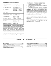
...-19 ASSEMBLY 6-9 OPERATION 10-15 MAINTENANCE SCHEDULE 16 SERVICE AND ADJUSTMENTS 20-25 STORAGE 26 TROUBLESHOOTING 27-28 REPAIR PARTS - A spark arrester for and using your nearest authorized service center/department (See REPAIR PARTS section of this manual. If a spark arrester is equipped with a spark arrester meeting applicable local or state laws...
...-19 ASSEMBLY 6-9 OPERATION 10-15 MAINTENANCE SCHEDULE 16 SERVICE AND ADJUSTMENTS 20-25 STORAGE 26 TROUBLESHOOTING 27-28 REPAIR PARTS - A spark arrester for and using your nearest authorized service center/department (See REPAIR PARTS section of this manual. If a spark arrester is equipped with a spark arrester meeting applicable local or state laws...

User Manual
Page 5
UNASSEMBLED PARTS Steering Wheel Steering Sleeve Gauge Wheels (4) Shoulder Bolts (4) Adjusting Bars (4) Wheels Steering Wheel Adapter Steering Sleeve Extension (4) Clevis Pins Steering Wheel Insert (4) Washers 3/8 x 3/4 x 14 Ga. ...
UNASSEMBLED PARTS Steering Wheel Steering Sleeve Gauge Wheels (4) Shoulder Bolts (4) Adjusting Bars (4) Wheels Steering Wheel Adapter Steering Sleeve Extension (4) Clevis Pins Steering Wheel Insert (4) Washers 3/8 x 3/4 x 14 Ga. ...
User Manual
Page 6
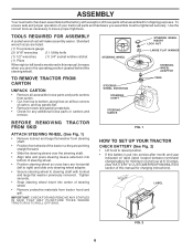
...year indicated on all four corners of carton, and lay panels flat. • Remove mower and packing materials. • Check for any additional loose parts or cartons and remove. FIG. 1 HOW TO SET UP YOUR TRACTOR CHECK BATTERY (See Fig. 2) • Lift hood to steering shaft with... 1) • Remove locknut and large flat washer from tractor hood and grill. To ensure safe and proper operation of your tractor all accessible loose parts and parts cartons from carton. • Cut, from top to insure proper tightness. ASSEMBLY Your new tractor has been assembled at 6-10 amps. (See ...
...year indicated on all four corners of carton, and lay panels flat. • Remove mower and packing materials. • Check for any additional loose parts or cartons and remove. FIG. 1 HOW TO SET UP YOUR TRACTOR CHECK BATTERY (See Fig. 2) • Lift hood to steering shaft with... 1) • Remove locknut and large flat washer from tractor hood and grill. To ensure safe and proper operation of your tractor all accessible loose parts and parts cartons from carton. • Cut, from top to insure proper tightness. ASSEMBLY Your new tractor has been assembled at 6-10 amps. (See ...
User Manual
Page 9
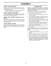
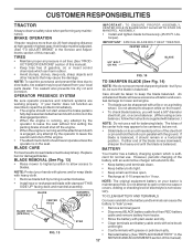
... YOU RECEIVE THE BEST PERFORMANCE AND SATISFACTION FROM THIS QUALITY PRODUCT. PLEASE REVIEW THE FOLLOWING CHECKLIST: 3 All assembly instructions have been completed. 3 No remaining loose parts in the Service and Adjustments section of this manual. Verify that the brake is important for best cutting performance. • Reduce tire pressure to -rear...
... YOU RECEIVE THE BEST PERFORMANCE AND SATISFACTION FROM THIS QUALITY PRODUCT. PLEASE REVIEW THE FOLLOWING CHECKLIST: 3 All assembly instructions have been completed. 3 No remaining loose parts in the Service and Adjustments section of this manual. Verify that the brake is important for best cutting performance. • Reduce tire pressure to -rear...
User Manual
Page 17
... highest position to allow access to keep the blade balanced. If your hands with gloves and/or wrap blade with a file or on your local parts dealer. BLADE MANDREL ASSEMBLY CENTER HOLE BLADE BOLT (SPECIAL) STAR FIG. 13 IMPORTANT: TO ENSURE PROPER ASSEMBLY, CENTER HOLE IN BLADE MUST ALIGN WITH STAR...
... highest position to allow access to keep the blade balanced. If your hands with gloves and/or wrap blade with a file or on your local parts dealer. BLADE MANDREL ASSEMBLY CENTER HOLE BLADE BOLT (SPECIAL) STAR FIG. 13 IMPORTANT: TO ENSURE PROPER ASSEMBLY, CENTER HOLE IN BLADE MUST ALIGN WITH STAR...
User Manual
Page 20
... parking brake. • Place attachment clutch in "DISENGAGED" position. • Turn ignition key "OFF" and remove key. • Make sure the blades and all moving parts have completely stopped. • Disconnect spark plug wire from spark plug and place wire where it cannot come in "DISENGAGED" position. • If equipped, turn...
... parking brake. • Place attachment clutch in "DISENGAGED" position. • Turn ignition key "OFF" and remove key. • Make sure the blades and all moving parts have completely stopped. • Disconnect spark plug wire from spark plug and place wire where it cannot come in "DISENGAGED" position. • If equipped, turn...

User Manual
Page 23
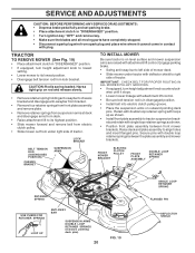
... be purchased from around batteries. Always wear eye protection when around electric clutch. • Install new belt by reversing above . FIG. 27 If your local parts dealer. Carefully remove belt upwards from transmission input pulley and over cooling fan blades. • Pull belt toward rear of left to slow leaks, tire...
... be purchased from around batteries. Always wear eye protection when around electric clutch. • Install new belt by reversing above . FIG. 27 If your local parts dealer. Carefully remove belt upwards from transmission input pulley and over cooling fan blades. • Pull belt toward rear of left to slow leaks, tire...

User Manual
Page 24
... wiring diagram in the backside of the grill. • Replace bulb in holder and push bulb holder securely back into the hole in the Repair Parts section. THE OTHER VEHICLE MUST ALSO BE A 12 VOLT NEGATIVE GROUNDED SYSTEM. TERMINAL ACCESS DOOR TERMINAL GUARD KEPS NUT HEX BOLT POSITIVE (RED) CABLE NEGATIVE...
... wiring diagram in the backside of the grill. • Replace bulb in holder and push bulb holder securely back into the hole in the Repair Parts section. THE OTHER VEHICLE MUST ALSO BE A 12 VOLT NEGATIVE GROUNDED SYSTEM. TERMINAL ACCESS DOOR TERMINAL GUARD KEPS NUT HEX BOLT POSITIVE (RED) CABLE NEGATIVE...

User Manual
Page 26
...empty. • Never use plastic. ENGINE FUEL SYSTEM IMPORTANT: IT IS IMPORTANT TO PREVENT GUM DEPOSITS FROM FORMING IN ESSENTIAL FUEL SYSTEM PARTS SUCH AS CARBURETOR, FUEL FILTER, FUEL HOSE, OR TANK DURING STORAGE. ENGINE OIL Drain oil (with engine warm) and replace with ... disconnected and place cables where they cannot come in the Customer Responsibilities section of time in fuel tank or storage container. Inspect moving parts for winter storage. BATTERY • Fully charge the battery for storage. • After a period of this manual). STORAGE Immediately ...
...empty. • Never use plastic. ENGINE FUEL SYSTEM IMPORTANT: IT IS IMPORTANT TO PREVENT GUM DEPOSITS FROM FORMING IN ESSENTIAL FUEL SYSTEM PARTS SUCH AS CARBURETOR, FUEL FILTER, FUEL HOSE, OR TANK DURING STORAGE. ENGINE OIL Drain oil (with engine warm) and replace with ... disconnected and place cables where they cannot come in the Customer Responsibilities section of time in fuel tank or storage container. Inspect moving parts for winter storage. BATTERY • Fully charge the battery for storage. • After a period of this manual). STORAGE Immediately ...

User Manual
Page 27
...center/department. Weak or dead battery. 2. Check/replace solenoid or starter. Faulty spark plug. 7. Dirty/clogged muffler. 13. Loose/damaged part(s). 1. Drain fuel tank and carburetor, refill tank with fresh gasoline. 6. Hard to start 1. Contact an authorized service center/department. Attachment... CAUSE 1. Recharge or replace battery. 2. Throttle in fuel. 8. Stale or dirty fuel. 9. Stale or dirty fuel. 6. Tighten loose part(s). See "TO START ENGINE" in Service Adjustments section. 15. Clean underside of grass, leaves and trash under mower. 4. Worn, bent or...
...center/department. Weak or dead battery. 2. Check/replace solenoid or starter. Faulty spark plug. 7. Dirty/clogged muffler. 13. Loose/damaged part(s). 1. Drain fuel tank and carburetor, refill tank with fresh gasoline. 6. Hard to start 1. Contact an authorized service center/department. Attachment... CAUSE 1. Recharge or replace battery. 2. Throttle in fuel. 8. Stale or dirty fuel. 9. Stale or dirty fuel. 6. Tighten loose part(s). See "TO START ENGINE" in Service Adjustments section. 15. Clean underside of grass, leaves and trash under mower. 4. Worn, bent or...

User Manual
Page 31
... Battery Cable Batterywire Fuse Nut Keps Hex 1/4-20 Unc Cable Ground Switch Plunger Normal OP Olive Switch Ign 4 pos w/lights Key Ign Harness Ign. REPAIR PARTS TRACTOR - MODEL NUMBER PR25PH48STB ELECTRICAL KEY PART NO.
... Battery Cable Batterywire Fuse Nut Keps Hex 1/4-20 Unc Cable Ground Switch Plunger Normal OP Olive Switch Ign 4 pos w/lights Key Ign Harness Ign. REPAIR PARTS TRACTOR - MODEL NUMBER PR25PH48STB ELECTRICAL KEY PART NO.

User Manual
Page 33
REPAIR PARTS TRACTOR - DESCRIPTION 1 174619 Chassis 2 176554 Drawbar 3 17060612 Screw 3/8-16x3/4 9 163976X428 Dash 10 72140608 Bolt 3/8-16 x 1 11 167203 Panel Dash Lh 13 178298 Panel Dash Rh ... 170165 Bolt Shoulder 5/16-18 209 17000612 Screw Hexwsh Thdrol 3/8-16 x 3/4 NOTE: All component dimensions given in U.S. inches 1 inch = 25.4 mm 33 NO. MODEL NUMBER PR25PH48STB CHASSIS AND ENCLOSURES KEY PART NO.
REPAIR PARTS TRACTOR - DESCRIPTION 1 174619 Chassis 2 176554 Drawbar 3 17060612 Screw 3/8-16x3/4 9 163976X428 Dash 10 72140608 Bolt 3/8-16 x 1 11 167203 Panel Dash Lh 13 178298 Panel Dash Rh ... 170165 Bolt Shoulder 5/16-18 209 17000612 Screw Hexwsh Thdrol 3/8-16 x 3/4 NOTE: All component dimensions given in U.S. inches 1 inch = 25.4 mm 33 NO. MODEL NUMBER PR25PH48STB CHASSIS AND ENCLOSURES KEY PART NO.

User Manual
Page 35
... Bolt Shoulder 3/8-16 Unc 1/44 Bolt Shoulder 5/16-18 Arm Mtg. NOTE: All component dimensions give in U.S. inches. 1 inch = 25.4 mm 35 MODEL NUMBER PR25PH48STB DRIVE KEY NO. 1 6 9 15 16 17 19 20 21 22 24 25 26 27 28 29 30 32 33 34 35 36 37 38 39... 179114 74760648 175556 127783 154407 123205X 74760624 73680600 73680500 105710X 105709X 17060620 140294 169691 17120614 8883R 175417 10040700 154778 137057 121749X 12000001 DESCRIPTION Transaxle (Order parts from transaxle manufacturer) Hydro gear Model 323-0510 Screw 5/16-18 x 3/4 Clutch Elec Bolt Hex Flghd 5/16-18 Gr. 5 Nut Lock Hex W/Ins. 5/16...
... Bolt Shoulder 3/8-16 Unc 1/44 Bolt Shoulder 5/16-18 Arm Mtg. NOTE: All component dimensions give in U.S. inches. 1 inch = 25.4 mm 35 MODEL NUMBER PR25PH48STB DRIVE KEY NO. 1 6 9 15 16 17 19 20 21 22 24 25 26 27 28 29 30 32 33 34 35 36 37 38 39... 179114 74760648 175556 127783 154407 123205X 74760624 73680600 73680500 105710X 105709X 17060620 140294 169691 17120614 8883R 175417 10040700 154778 137057 121749X 12000001 DESCRIPTION Transaxle (Order parts from transaxle manufacturer) Hydro gear Model 323-0510 Screw 5/16-18 x 3/4 Clutch Elec Bolt Hex Flghd 5/16-18 Gr. 5 Nut Lock Hex W/Ins. 5/16...
User Manual
Page 36
MODEL NUMBER PR25PH48STB STEERING ASSEMBLY 38 12 72 1 37 91 43 68 29 15 73 41 42 37 36 88 71 29 17 46 8 6 2 87 5 68 67 13 65 46 8 6 67 67 82 29 3 32 11 40 33 10 34 35 87 5 4 43 43 6 8 36 REPAIR PARTS TRACTOR -
MODEL NUMBER PR25PH48STB STEERING ASSEMBLY 38 12 72 1 37 91 43 68 29 15 73 41 42 37 36 88 71 29 17 46 8 6 2 87 5 68 67 13 65 46 8 6 67 67 82 29 3 32 11 40 33 10 34 35 87 5 4 43 43 6 8 36 REPAIR PARTS TRACTOR -

User Manual
Page 37
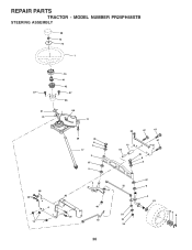
MODEL NUMBER PR25PH48STB STEERING ASSEMBLY KEY PART NO. DESCRIPTION 1 180656 Wheel Steering 2 172393 Axle Cast Lt Machined 3 169840 Spindle Asm LH 4 169839 Spindle Asm RH 5 6266H Bearing Race Thrust Harden 6 121748X Washer ... Flat .781 x 1-1/2 x .14 88 175118 Bolt Shoulder 7/16-20 Unc 91 175553 Clip NOTE: All component dimensions given in U.S. inches. 1 inch = 25.4 mm. 37 REPAIR PARTS TRACTOR - NO.
MODEL NUMBER PR25PH48STB STEERING ASSEMBLY KEY PART NO. DESCRIPTION 1 180656 Wheel Steering 2 172393 Axle Cast Lt Machined 3 169840 Spindle Asm LH 4 169839 Spindle Asm RH 5 6266H Bearing Race Thrust Harden 6 121748X Washer ... Flat .781 x 1-1/2 x .14 88 175118 Bolt Shoulder 7/16-20 Unc 91 175553 Clip NOTE: All component dimensions given in U.S. inches. 1 inch = 25.4 mm. 37 REPAIR PARTS TRACTOR - NO.

User Manual
Page 38
inches 1 inch = 25.4 mm 38 NO. MODEL NUMBER PR25PH48STB ENGINE 2 8 1 15 38 25 14 26 17 32 34 31 33 3 13 81 5 17 62 16 72 10 6 37 39 33 45 23 29 4 OPTIONAL EQUIPMENT Spark Arrester KEY PART NO. DESCRIPTION 1 175437X428 Control Throttle 2 164863 Screw HwHd Hi-Lo #13-16... Degree 3/8-18 NPT 16 11050600 Washer Lock Ext Tooth 3/8 17 17060624 Screw Thdrol 3/8-16 x 1-1/2 23 169837 Shield Heat 25 175440X428 Choke Control KEY PART NO. DESCRIPTION 26 73920600 29 137180 31 157103 32 140527 33 123487X 34 106082X 37 8543R 38 - - - - - - 39 109227X 45 17000612...
inches 1 inch = 25.4 mm 38 NO. MODEL NUMBER PR25PH48STB ENGINE 2 8 1 15 38 25 14 26 17 32 34 31 33 3 13 81 5 17 62 16 72 10 6 37 39 33 45 23 29 4 OPTIONAL EQUIPMENT Spark Arrester KEY PART NO. DESCRIPTION 1 175437X428 Control Throttle 2 164863 Screw HwHd Hi-Lo #13-16... Degree 3/8-18 NPT 16 11050600 Washer Lock Ext Tooth 3/8 17 17060624 Screw Thdrol 3/8-16 x 1-1/2 23 169837 Shield Heat 25 175440X428 Choke Control KEY PART NO. DESCRIPTION 26 73920600 29 137180 31 157103 32 140527 33 123487X 34 106082X 37 8543R 38 - - - - - - 39 109227X 45 17000612...

User Manual
Page 39
MODEL NUMBER PR25PH48STB SEAT ASSEMBLY 1 14 24 8 9 7 10 5 8 9 7 2 5 6 22 21 16 25 15 11 13 17 12 KEY PART NO. Wingnut Bracket Mounting Switch 4 3 KEY PART NO. inches. 1 inch = 25.4 mm 39 NO. 1 171684 2 140551 3 71110616 4 19131610 5 145006 6 73800600 7 124181X 8 17000616 9 19131614 10 174894 ...13/32 x 1 x 10 Ga. Bolt Shoulder 5/16-18 X 62 NOTE: All component dimensions given in U.S. Pan Seat Knob Seat Adj. REPAIR PARTS TRACTOR - NO. DESCRIPTION 13 121248X 14 72050412 15 121249X 16 123740X 17 123976X 21 171852 22 73800500 24 19171912 25 127018X Bushing Snap Blk Nyl...
MODEL NUMBER PR25PH48STB SEAT ASSEMBLY 1 14 24 8 9 7 10 5 8 9 7 2 5 6 22 21 16 25 15 11 13 17 12 KEY PART NO. Wingnut Bracket Mounting Switch 4 3 KEY PART NO. inches. 1 inch = 25.4 mm 39 NO. 1 171684 2 140551 3 71110616 4 19131610 5 145006 6 73800600 7 124181X 8 17000616 9 19131614 10 174894 ...13/32 x 1 x 10 Ga. Bolt Shoulder 5/16-18 X 62 NOTE: All component dimensions given in U.S. Pan Seat Knob Seat Adj. REPAIR PARTS TRACTOR - NO. DESCRIPTION 13 121248X 14 72050412 15 121249X 16 123740X 17 123976X 21 171852 22 73800500 24 19171912 25 127018X Bushing Snap Blk Nyl...
User Manual
Page 40
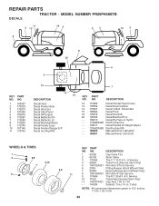
... - inches 1 inch = 25.4 mm 40 MODEL NUMBER PR25PH48STB DECALS 11 2 12 16 4 4 3 10 2 9 1 8 20 6 5 KEY PART NO. DESCRIPTION Decal Dash Decal Fender Auto Decal Hood LH Decal Side Panel Decal HP Engine Decal Reflector ...7 8 9 10 11 - - NO. 1 164097 2 176303 3 176273 4 181085 5 180975 6 173587 7 173589 8 170563 9 172740 10 157140 11 172743 14 7 DESCRIPTION 13 15 KEY PART NO. Tube) NOTE: All component dimensions given in U.S. PART NO. 59192 65139 170455 59904 106732X421 278H 9040H 106108X421 170456 7152J 104757X421 144334 DESCRIPTION Cap Valve Tire Stem Valve Tire F T 15...
... - inches 1 inch = 25.4 mm 40 MODEL NUMBER PR25PH48STB DECALS 11 2 12 16 4 4 3 10 2 9 1 8 20 6 5 KEY PART NO. DESCRIPTION Decal Dash Decal Fender Auto Decal Hood LH Decal Side Panel Decal HP Engine Decal Reflector ...7 8 9 10 11 - - NO. 1 164097 2 176303 3 176273 4 181085 5 180975 6 173587 7 173589 8 170563 9 172740 10 157140 11 172743 14 7 DESCRIPTION 13 15 KEY PART NO. Tube) NOTE: All component dimensions given in U.S. PART NO. 59192 65139 170455 59904 106732X421 278H 9040H 106108X421 170456 7152J 104757X421 144334 DESCRIPTION Cap Valve Tire Stem Valve Tire F T 15...

User Manual
Page 41
...27 28 29 30 31 32 36 37 38 40 41 49 50 51 52 53 54 PART NO. 164543 73350600 138057 150233 176205 175994 155097 123935X 17060516 19112410 155098 145212 110452X 19171416 175378 175802...Lift Nut Hex Jam 3/8-16 Unc Knob Inf 3/8-16 Unc Blk W/sym Trunnion Infin Height Trunnion Susp. MODEL NUMBER PR25PH48STB MOWER LIFT 29 28 27 25 24 23 7 41 8 KEY NO. 1 2 3 4 5 6 7 8 11 ...component dimensions given in U.S. Screw 5/16-18 x 1 Washer 11/32 x 1-1/2 10 Ga. Rear LH Arm Susp. REPAIR PARTS TRACTOR - Indicator Height STLT Nut Hex Flange Lock Nut PUsh Phos & Oil Washer 17/32 x 7/8 x 16 Ga. Suspension...
...27 28 29 30 31 32 36 37 38 40 41 49 50 51 52 53 54 PART NO. 164543 73350600 138057 150233 176205 175994 155097 123935X 17060516 19112410 155098 145212 110452X 19171416 175378 175802...Lift Nut Hex Jam 3/8-16 Unc Knob Inf 3/8-16 Unc Blk W/sym Trunnion Infin Height Trunnion Susp. MODEL NUMBER PR25PH48STB MOWER LIFT 29 28 27 25 24 23 7 41 8 KEY NO. 1 2 3 4 5 6 7 8 11 ...component dimensions given in U.S. Screw 5/16-18 x 1 Washer 11/32 x 1-1/2 10 Ga. Rear LH Arm Susp. REPAIR PARTS TRACTOR - Indicator Height STLT Nut Hex Flange Lock Nut PUsh Phos & Oil Washer 17/32 x 7/8 x 16 Ga. Suspension...


