
User Manual
Page 2
... Practices for holes, ruts, or bumps. I. presence of objects such as rocks, tree limbs, etc. • Watch for Ride-On Mowers IMPORTANT: THIS CUTTING MACHINE IS CAPABLE OF AMPUTATING HANDS AND FEET AND THROWING OBJECTS. They may obscure vision. SERVICE • Use extra care... blades and proceed slowly straight down slopes, not across. • Remove obstacles such as rocks, toys, wire, etc., which can cut. The mower could overturn the machine. Do • Keep machine free of riding mowerrelated injuries. All slopes require extra caution. Choose a low gear so that...
... Practices for holes, ruts, or bumps. I. presence of objects such as rocks, tree limbs, etc. • Watch for Ride-On Mowers IMPORTANT: THIS CUTTING MACHINE IS CAPABLE OF AMPUTATING HANDS AND FEET AND THROWING OBJECTS. They may obscure vision. SERVICE • Use extra care... blades and proceed slowly straight down slopes, not across. • Remove obstacles such as rocks, toys, wire, etc., which can cut. The mower could overturn the machine. Do • Keep machine free of riding mowerrelated injuries. All slopes require extra caution. Choose a low gear so that...
User Manual
Page 3
... spark plug wire and place wire where it cannot contact spark plug. Always look behind before mowing. SAFETY RULES Safe Operation Practices for Ride-On Mowers • Be sure the area is dangerous. YOUR SAFETY IS INVOLVED. Tall grass can lose traction with safe machine operation. • Keep children out of...
... spark plug wire and place wire where it cannot contact spark plug. Always look behind before mowing. SAFETY RULES Safe Operation Practices for Ride-On Mowers • Be sure the area is dangerous. YOUR SAFETY IS INVOLVED. Tall grass can lose traction with safe machine operation. • Keep children out of...
User Manual
Page 6
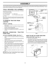
... securely. • Snap steering wheel insert into center of those parts left hand is put into bottom of carton, and lay panels flat. • Remove mower and packing materials. • Check for minimum of one hour at the factory with locknut and large flat washer previously removed. STEERING WHEEL EXTENTION STEERING...
... securely. • Snap steering wheel insert into center of those parts left hand is put into bottom of carton, and lay panels flat. • Remove mower and packing materials. • Check for minimum of one hour at the factory with locknut and large flat washer previously removed. STEERING WHEEL EXTENTION STEERING...

User Manual
Page 8
...EQUIPPED WITH HIGH PERFORMANCE BLADES, WHICH ARE THE BEST BLADES FOR BAGGING AND DISCHARGING. TO USE YOUR MOWER WITH THE HIGH PERFORMANCE BLADES THE MULCHER PLATE MUST BE REMOVED FROM THE MOWER (SEE FIG. 4). Raise and hold deflector shield in the Maintenance section of optional grass catcher accessory... mulcher plate and allow it to rest on back of this manual). .• Store mulcher blades and mulcher plate in operation. Your mower is now ready for best bagging and discharging install the high performance blades. • Remove mulcher plate and mulcher blades and install high...
...EQUIPPED WITH HIGH PERFORMANCE BLADES, WHICH ARE THE BEST BLADES FOR BAGGING AND DISCHARGING. TO USE YOUR MOWER WITH THE HIGH PERFORMANCE BLADES THE MULCHER PLATE MUST BE REMOVED FROM THE MOWER (SEE FIG. 4). Raise and hold deflector shield in the Maintenance section of optional grass catcher accessory... mulcher plate and allow it to rest on back of this manual). .• Store mulcher blades and mulcher plate in operation. Your mower is now ready for best bagging and discharging install the high performance blades. • Remove mulcher plate and mulcher blades and install high...
User Manual
Page 9
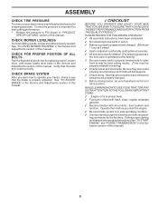
...ALL BELTS See the figures that the brake is important to -rear for best cutting results. (Tires must be properly inflated for leveling). 3 Check mower and drive belts. PLEASE REVIEW THE FOLLOWING CHECKLIST: 3 All assembly instructions have been completed. 3 No remaining loose parts in carton. 3 Battery ... with all controls - ing your tractor, check to PSI shown in the Service and Adjustments section of this manual. See "TO LEVEL MOWER HOUSING" in the Service and Adjustments section of this manual. 3CHECKLIST BEFORE YOU OPERATE AND ENJOY YOUR NEW TRACTOR, WE WISH TO ASSURE THAT...
...ALL BELTS See the figures that the brake is important to -rear for best cutting results. (Tires must be properly inflated for leveling). 3 Check mower and drive belts. PLEASE REVIEW THE FOLLOWING CHECKLIST: 3 All assembly instructions have been completed. 3 No remaining loose parts in carton. 3 Battery ... with all controls - ing your tractor, check to PSI shown in the Service and Adjustments section of this manual. See "TO LEVEL MOWER HOUSING" in the Service and Adjustments section of this manual. 3CHECKLIST BEFORE YOU OPERATE AND ENJOY YOUR NEW TRACTOR, WE WISH TO ASSURE THAT...
User Manual
Page 10
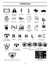
BATTERY CAUTION OR WARNING REVERSE FORWARD FAST SLOW ENGINE ON ENGINE OFF OIL PRESSURE LIGHTS ON OVER TEMP LIGHT FUEL CHOKE MOWER HEIGHT PARKING BRAKE LOCKED UNLOCKED MOWER LIFT ATTACHMENT REVERSE CLUTCH ENGAGED NEUTRAL HIGH P LOW PARKING BRAKE 15 15 15 IGNITION ATTACHMENT CLUTCH DISENGAGED KEEP AREA CLEAR SLOPE HAZARDS (SEE SAFETY RULES SECTION) DANGER, KEEP HANDS AND FEET AWAY 10 FREE WHEEL (Automatic Models only) Learn and understand their meaning. OPERATION These symbols may appear on your tractor or in literature supplied with the product.
BATTERY CAUTION OR WARNING REVERSE FORWARD FAST SLOW ENGINE ON ENGINE OFF OIL PRESSURE LIGHTS ON OVER TEMP LIGHT FUEL CHOKE MOWER HEIGHT PARKING BRAKE LOCKED UNLOCKED MOWER LIFT ATTACHMENT REVERSE CLUTCH ENGAGED NEUTRAL HIGH P LOW PARKING BRAKE 15 15 15 IGNITION ATTACHMENT CLUTCH DISENGAGED KEEP AREA CLEAR SLOPE HAZARDS (SEE SAFETY RULES SECTION) DANGER, KEEP HANDS AND FEET AWAY 10 FREE WHEEL (Automatic Models only) Learn and understand their meaning. OPERATION These symbols may appear on your tractor or in literature supplied with the product.
User Manual
Page 11
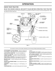
...for pushing or slowly towing the tractor with the locations of tractor. HEIGHT ADJUSTMENT KNOB - Used to raise and lower the mower deck or other attachments mounted to your tractor. IGNITION SWITCH - Save this manual for starting and stopping the engine. ATTACHMENT CLUTCH... SWITCH: Used to engage the mower blades, or other attachments mounted to your tractor. Used to set forward movement of battery. Disengages transmission for braking the tractor...
...for pushing or slowly towing the tractor with the locations of tractor. HEIGHT ADJUSTMENT KNOB - Used to raise and lower the mower deck or other attachments mounted to your tractor. IGNITION SWITCH - Save this manual for starting and stopping the engine. ATTACHMENT CLUTCH... SWITCH: Used to engage the mower blades, or other attachments mounted to your tractor. Used to set forward movement of battery. Disengages transmission for braking the tractor...

User Manual
Page 12
...• Turn knob clockwise ( ) to raise cutting height. • Turn knob counterclockwise ( ) to empty grass catcher, etc. TO ADJUST MOWER CUTTING HEIGHT (See Fig. 6) IMPORTANT: FORWARD AND REVERSE DRIVE PEDALS RETURN TO NEUTRAL POSITION WHEN NOT DEPRESSED. Always remove key when leaving tractor to... The heights are starting a cold engine. the second to prevent unauthorized use to slow position. FIG. 6 STOPPING (See Fig. 6) MOWER BLADES - • With forward drive pedal depressed to desired speed, move throttle control to slow position and allowing engine to idle before ...
...• Turn knob clockwise ( ) to raise cutting height. • Turn knob counterclockwise ( ) to empty grass catcher, etc. TO ADJUST MOWER CUTTING HEIGHT (See Fig. 6) IMPORTANT: FORWARD AND REVERSE DRIVE PEDALS RETURN TO NEUTRAL POSITION WHEN NOT DEPRESSED. Always remove key when leaving tractor to... The heights are starting a cold engine. the second to prevent unauthorized use to slow position. FIG. 6 STOPPING (See Fig. 6) MOWER BLADES - • With forward drive pedal depressed to desired speed, move throttle control to slow position and allowing engine to idle before ...

User Manual
Page 13
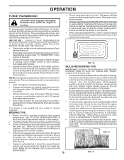
...with slopes greater than two (2) MPH. • To reengage transmission, reverse above procedure. Use an appropriate means of cut. • Lower mower with tractor on hills. • If stopping is absolutely necessary, push brake pedal quickly to brake position and engage parking brake. • .... • Pull freewheel control out and into clevis pin. • Be sure all turns slowly. RETAINER SPRING CLEVIS PIN FIG. 7 TO OPERATE MOWER (See Fig. 8) Your tractor is closed and secured to ground. TO TRANSPORT (See Figs. 5 and 9) When pushing or towing your tractor. FIG...
...with slopes greater than two (2) MPH. • To reengage transmission, reverse above procedure. Use an appropriate means of cut. • Lower mower with tractor on hills. • If stopping is absolutely necessary, push brake pedal quickly to brake position and engage parking brake. • .... • Pull freewheel control out and into clevis pin. • Be sure all turns slowly. RETAINER SPRING CLEVIS PIN FIG. 7 TO OPERATE MOWER (See Fig. 8) Your tractor is closed and secured to ground. TO TRANSPORT (See Figs. 5 and 9) When pushing or towing your tractor. FIG...
User Manual
Page 15
... reverse position, hold for normal operation. This will not be exposed to the direct sun. • For best results, adjust the mower cutting height so that the transmission be properly leveled for trimming. • Drive so that clippings are discharged onto the area that clippings... parking brake. • Drive tractor forward for approximately five feet then backwards for the first time. Also, the mulched grass will plug mower and leave undesirable clumps. Depress reverse drive pedal to reduce load and possible fire hazard from hydraulic drive system. • Shut- The ...
... reverse position, hold for normal operation. This will not be exposed to the direct sun. • For best results, adjust the mower cutting height so that the transmission be properly leveled for trimming. • Drive so that clippings are discharged onto the area that clippings... parking brake. • Drive tractor forward for approximately five feet then backwards for the first time. Also, the mulched grass will plug mower and leave undesirable clumps. Depress reverse drive pedal to reduce load and possible fire hazard from hydraulic drive system. • Shut- The ...

User Manual
Page 16
... IN DATES AS YOU COMPLETE REGULAR SERVICE Check Brake Operation Check Tire Pressure Check Operator Presence and T Interlock Systems R Check for Loose Fasteners A Sharpen/Replace Mower Blades C T Lubrication Chart 0 Check Battery Level R Clean Battery and Terminals Check Transaxle Cooling Check V-Belts BEFOREEEVAECRHYU8ESVHEEORUYRS2E5VHEROYUR5E0SVEHROYUR1E0SV0EHROYUBSREESFAOSROEN STORAGE SERVICE DATES 5 3 4 Check Engine Oil Level Change Engine...
... IN DATES AS YOU COMPLETE REGULAR SERVICE Check Brake Operation Check Tire Pressure Check Operator Presence and T Interlock Systems R Check for Loose Fasteners A Sharpen/Replace Mower Blades C T Lubrication Chart 0 Check Battery Level R Clean Battery and Terminals Check Transaxle Cooling Check V-Belts BEFOREEEVAECRHYU8ESVHEEORUYRS2E5VHEROYUR5E0SVEHROYUR1E0SV0EHROYUBSREESFAOSROEN STORAGE SERVICE DATES 5 3 4 Check Engine Oil Level Change Engine...
User Manual
Page 17
...the blade is balanced. TRAILING EDGE UP BLADE MANDREL ASSEMBLY CENTER HOLE FLAT WASHER LOCK WASHER STAR NOTE: The original equipment battery on the mower. • To check blade balance, you do not recommend sharpening blade - Adding or checking level of electrolyte is not necessary. FIG....8226; Avoid stumps, stones, deep ruts, sharp objects and other hazards that may cause tire damage. Lbs. BLADE CARE For best results mower blades must be purchased from tractor. • Rinse the battery with plain water and dry. CUSTOMER RESPONSIBILITIES TRACTOR Always observe safety rules ...
...the blade is balanced. TRAILING EDGE UP BLADE MANDREL ASSEMBLY CENTER HOLE FLAT WASHER LOCK WASHER STAR NOTE: The original equipment battery on the mower. • To check blade balance, you do not recommend sharpening blade - Adding or checking level of electrolyte is not necessary. FIG....8226; Avoid stumps, stones, deep ruts, sharp objects and other hazards that may cause tire damage. Lbs. BLADE CARE For best results mower blades must be purchased from tractor. • Rinse the battery with plain water and dry. CUSTOMER RESPONSIBILITIES TRACTOR Always observe safety rules ...
User Manual
Page 20
...retainer springs. • Disconnect front links from deck by removing retainer springs. • Raise lift lever to raise suspension arms. Slide mower out from spark plug and place wire where it cannot come in "DISENGAGED" position. • Move attachment lift lever forward to lower... mower to its lowest position. • Connect front links to mower deck and secure with retainer springs.. • Connect suspension arms to rear deck brackets and secure with retainer springs....
...retainer springs. • Disconnect front links from deck by removing retainer springs. • Raise lift lever to raise suspension arms. Slide mower out from spark plug and place wire where it cannot come in "DISENGAGED" position. • Move attachment lift lever forward to lower... mower to its lowest position. • Connect front links to mower deck and secure with retainer springs.. • Connect suspension arms to rear deck brackets and secure with retainer springs....

User Manual
Page 21
...in length, adjust one link to its highest position. To obtain the best cutting results, the mower housing should be replaced without tools. Measure distance "D" directly in this manual). BELT REMOVAL • Remove mower from mower. 21 MANDREL "D" "D" FIG. 20 BOTH FRONT LINKS MUST BE EQUAL IN LENGTH A GROUND ... ADJUSTMENT (See Figs. 20 and 21) IMPORTANT: DECK MUST BE LEVEL SIDE-TO-SIDE. FRONT LINKS TRUNNION FIG. 21 TO REPLACE MOWER BLADE DRIVE BELT (See Fig. 22) The mower blade drive belt may be the same or within 1/4" of each other link. • To lower front of...
...in length, adjust one link to its highest position. To obtain the best cutting results, the mower housing should be replaced without tools. Measure distance "D" directly in this manual). BELT REMOVAL • Remove mower from mower. 21 MANDREL "D" "D" FIG. 20 BOTH FRONT LINKS MUST BE EQUAL IN LENGTH A GROUND ... ADJUSTMENT (See Figs. 20 and 21) IMPORTANT: DECK MUST BE LEVEL SIDE-TO-SIDE. FRONT LINKS TRUNNION FIG. 21 TO REPLACE MOWER BLADE DRIVE BELT (See Fig. 22) The mower blade drive belt may be the same or within 1/4" of each other link. • To lower front of...

User Manual
Page 22
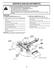
...side of the transaxle. If damage has occurred to right) when wheels are not horizontal (left footrest. • Remove mower (See "TO REMOVE MOWER" in or camber, contact your transmission require removal for proper stopping distance as stated above procedure. SERVICE AND ADJUSTMENTS BELT INSTALLATION...is equipped with an adjustable brake system which is in all pulley grooves and inside all belt guides. • Install mower (See "To Install Mower" in the Assembly section of manual). Readjust if necessary. IF FURTHER BRAKE ADJUSTMENT IS NECESSARY CONTACT YOUR NEAREST AUTHORIZED SERVICE ...
...side of the transaxle. If damage has occurred to right) when wheels are not horizontal (left footrest. • Remove mower (See "TO REMOVE MOWER" in or camber, contact your transmission require removal for proper stopping distance as stated above procedure. SERVICE AND ADJUSTMENTS BELT INSTALLATION...is equipped with an adjustable brake system which is in all pulley grooves and inside all belt guides. • Install mower (See "To Install Mower" in the Assembly section of manual). Readjust if necessary. IF FURTHER BRAKE ADJUSTMENT IS NECESSARY CONTACT YOUR NEAREST AUTHORIZED SERVICE ...

User Manual
Page 26
... require recharging. • To help prevent corrosion and power leakage during storage. Do not drain the gas tank and carburetor if using fuel stabilizer. When mower is to rust. ACIDIC GAS CAN DAMAGE THE FUEL SYSTEM OF AN ENGINE WHILE IN STORAGE. • Drain the fuel tank. • Start the engine... section of oil through spark plug hole(s) into cylinder(s). • Turn ignition key to "START" position for a few seconds to cool before painting. TRACTOR Remove mower from tractor for damage, breakage and wear.
... require recharging. • To help prevent corrosion and power leakage during storage. Do not drain the gas tank and carburetor if using fuel stabilizer. When mower is to rust. ACIDIC GAS CAN DAMAGE THE FUEL SYSTEM OF AN ENGINE WHILE IN STORAGE. • Drain the fuel tank. • Start the engine... section of oil through spark plug hole(s) into cylinder(s). • Turn ignition key to "START" position for a few seconds to cool before painting. TRACTOR Remove mower from tractor for damage, breakage and wear.

User Manual
Page 27
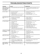
.... 4. Replace fuel filter. 7. Check all wiring. 7. Hard to start 1. Dirty air filter. 2. Dirty fuel filter. 5. Engine valves out of mower housing. 4. Replace fuel filter. 5. Check all wiring. 9. Recharge or replace battery. 4. Loose or damaged wiring. 4. Check all wiring. 7. Throttle...battery terminals. 6. Check/replace solenoid or starter. 9. Contact an authorized service center/department. Loss of grass, leaves and trash under mower. 4. Build-up of power 1. Water in Service Adjustments section. 8. Spark plug wire loose. 11. Loose or damaged wiring....
.... 4. Replace fuel filter. 7. Check all wiring. 7. Hard to start 1. Dirty air filter. 2. Dirty fuel filter. 5. Engine valves out of mower housing. 4. Replace fuel filter. 5. Check all wiring. 9. Recharge or replace battery. 4. Loose or damaged wiring. 4. Check all wiring. 7. Throttle...battery terminals. 6. Check/replace solenoid or starter. 9. Contact an authorized service center/department. Loss of grass, leaves and trash under mower. 4. Build-up of power 1. Water in Service Adjustments section. 8. Spark plug wire loose. 11. Loose or damaged wiring....
User Manual
Page 28
... Freewheel control in "FAST" position. 2. Place freewheel control in this manual. 11. Replace motion drive belt. 3. Replace blade. Worn/damaged mower drive belt. 3. Replace idler pulley. 4. Poor grass discharge 1. Engine speed too slow. 2. Worn, bent or loose blade. 7. Clean ...ON". 2. Check/replace light switch. 4. Replace battery. 2. Purge transmission. 1. Worn, bent or loose blade. 2. Bent blade mandrel. 5. Level mower deck. 3. Wet grass. 4. Blades improperly installed. 10. Switch is "OFF". 2. Air trapped in clutch mechanism. 2. Check wiring, switches and ...
... Freewheel control in "FAST" position. 2. Place freewheel control in this manual. 11. Replace motion drive belt. 3. Replace blade. Worn/damaged mower drive belt. 3. Replace idler pulley. 4. Poor grass discharge 1. Engine speed too slow. 2. Worn, bent or loose blade. 7. Clean ...ON". 2. Check/replace light switch. 4. Replace battery. 2. Purge transmission. 1. Worn, bent or loose blade. 2. Bent blade mandrel. 5. Level mower deck. 3. Wet grass. 4. Blades improperly installed. 10. Switch is "OFF". 2. Air trapped in clutch mechanism. 2. Check wiring, switches and ...
User Manual
Page 33
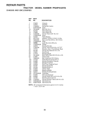
... W/Lens 30 175692X428 Fender 31 139976 Bracket Fender 37 17490508 Screw Thdrol 6/16-18 x 1/2 TYT 38 175710 Bracket, Asm. inches 1 inch = 25.4 mm 33 Pivot Mower Rear 54 161464 Screw Hex Wshd 8-18 x 7/8 58 175351 Duct Hood 59 177579 Bushing Snap 60 72140606 Bolt RdHd Sqnk 3/8-16 Unc x 3/4 64 174997 Dash... 209 17000612 Screw Hexwsh Thdrol 3/8-16 x 3/4 213 169848X428 Skirt Grille Lh 214 169847X428 Skirt Grille Rh NOTE: All component dimensions given in U.S. NO. MODEL NUMBER PR20PH42STA CHASSIS AND ENCLOSURES KEY PART NO. REPAIR PARTS TRACTOR -
... W/Lens 30 175692X428 Fender 31 139976 Bracket Fender 37 17490508 Screw Thdrol 6/16-18 x 1/2 TYT 38 175710 Bracket, Asm. inches 1 inch = 25.4 mm 33 Pivot Mower Rear 54 161464 Screw Hex Wshd 8-18 x 7/8 58 175351 Duct Hood 59 177579 Bushing Snap 60 72140606 Bolt RdHd Sqnk 3/8-16 Unc x 3/4 64 174997 Dash... 209 17000612 Screw Hexwsh Thdrol 3/8-16 x 3/4 213 169848X428 Skirt Grille Lh 214 169847X428 Skirt Grille Rh NOTE: All component dimensions given in U.S. NO. MODEL NUMBER PR20PH42STA CHASSIS AND ENCLOSURES KEY PART NO. REPAIR PARTS TRACTOR -
User Manual
Page 40
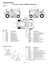
... (Front Wheel Only) Rim Asm 8"rear Service Tire R T 20x10 -8 C Service Tube Rear (Service Item Only) Cap Axle 1 50 X 1 00 Sealant, Tire ( 10 oz. MODEL NUMBER PR20PH42STA 11 2 12 16 4 4 3 13 10 2 9 1 8 15 20 6 5 14 KEY PART NO. NO. 1 164095 2 176303 3 176273 4 177020 5 170851 6 173587 7 173589 8 170563 9 172740 10 157140 ... DESCRIPTION Decal Dash Decal Fender Auto Decal Hood LH Decal Side Panel Decal HP Engine Decal Reflector Rh Decal Reflector Lh Decal Warning Mower Decal Fender Logo Decal Fender Danger E/F Decal Ins Strg Whl 7 KEY PART NO. REPAIR PARTS DECALS TRACTOR -
... (Front Wheel Only) Rim Asm 8"rear Service Tire R T 20x10 -8 C Service Tube Rear (Service Item Only) Cap Axle 1 50 X 1 00 Sealant, Tire ( 10 oz. MODEL NUMBER PR20PH42STA 11 2 12 16 4 4 3 13 10 2 9 1 8 15 20 6 5 14 KEY PART NO. NO. 1 164095 2 176303 3 176273 4 177020 5 170851 6 173587 7 173589 8 170563 9 172740 10 157140 ... DESCRIPTION Decal Dash Decal Fender Auto Decal Hood LH Decal Side Panel Decal HP Engine Decal Reflector Rh Decal Reflector Lh Decal Warning Mower Decal Fender Logo Decal Fender Danger E/F Decal Ins Strg Whl 7 KEY PART NO. REPAIR PARTS DECALS TRACTOR -


