
User Manual
Page 2
...before and while backing. • Beawareofthemowerdischargedirectionanddonotpoint it . These can occur if the operator is clear of other people before refueling. The mower could overturn the machine. III. Never remove gas cap or add fuel with the engine running. • Grass catcher components are...anddown for wheel weights or counterweights to improve stability. • Use extra care with manufacturer's recommended parts, when necessary. • Mower blades are subject to wear, damage, and deterioration, which could be picked up to cool before mowing. They are flammable and ...
...before and while backing. • Beawareofthemowerdischargedirectionanddonotpoint it . These can occur if the operator is clear of other people before refueling. The mower could overturn the machine. III. Never remove gas cap or add fuel with the engine running. • Grass catcher components are...anddown for wheel weights or counterweights to improve stability. • Use extra care with manufacturer's recommended parts, when necessary. • Mower blades are subject to wear, damage, and deterioration, which could be picked up to cool before mowing. They are flammable and ...

User Manual
Page 3
.... • Use slow speed. Always look behind and down and behind before mowing. Wash hands after handling. 3 SAFETY RULES Safe Operation Practices for Ride-On Mowers • Be sure the area is dangerous. Tall grass can lose traction with safe machine operation. • Keep children out of the mowing area and...
.... • Use slow speed. Always look behind and down and behind before mowing. Wash hands after handling. 3 SAFETY RULES Safe Operation Practices for Ride-On Mowers • Be sure the area is dangerous. Tall grass can lose traction with safe machine operation. • Keep children out of the mowing area and...
User Manual
Page 8
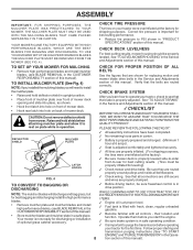
... SHIELD MULCHER PLATE ✓ All assembly instructions have been completed. ✓ No remaining loose parts in "PRODUCT SPECIFICATIONS" section of mower deck. Operate them before you learn how to install the mulcher plate. • Raise and hold shield when attaching mulcher plate and...TO START ENGINE" and "PURGE TRANSMISSION" in the Service and Adjustments section of this manual). Be sure they are routed correctly. Your mower is filled with fresh, clean, regular unleaded gasoline. ✓ Become familiar with all belt keepers. See that the belts are routed...
... SHIELD MULCHER PLATE ✓ All assembly instructions have been completed. ✓ No remaining loose parts in "PRODUCT SPECIFICATIONS" section of mower deck. Operate them before you learn how to install the mulcher plate. • Raise and hold shield when attaching mulcher plate and...TO START ENGINE" and "PURGE TRANSMISSION" in the Service and Adjustments section of this manual). Be sure they are routed correctly. Your mower is filled with fresh, clean, regular unleaded gasoline. ✓ Become familiar with all belt keepers. See that the belts are routed...

User Manual
Page 9
OPERATION These symbols may appear on your tractor or in literature supplied with the product. BATTERY CAUTION OR WARNING REVERSE FORWARD FAST SLOW ENGINE ON ENGINE OFF OIL PRESSURE LIGHTS ON OVER TEMP LIGHT FUEL CHOKE MOWER HEIGHT PARKING BRAKE LOCKED UNLOCKED MOWER LIFT ATTACHMENT REVERSE CLUTCH ENGAGED NEUTRAL HIGH P LOW PARKING BRAKE 15 15 15 IGNITION ATTACHMENT CLUTCH DISENGAGED KEEP AREA CLEAR SLOPE HAZARDS (SEE SAFETY RULES SECTION) DANGER, KEEP HANDS AND FEET AWAY 9 FREE WHEEL (Automatic Models only) Learn and understand their meaning.
OPERATION These symbols may appear on your tractor or in literature supplied with the product. BATTERY CAUTION OR WARNING REVERSE FORWARD FAST SLOW ENGINE ON ENGINE OFF OIL PRESSURE LIGHTS ON OVER TEMP LIGHT FUEL CHOKE MOWER HEIGHT PARKING BRAKE LOCKED UNLOCKED MOWER LIFT ATTACHMENT REVERSE CLUTCH ENGAGED NEUTRAL HIGH P LOW PARKING BRAKE 15 15 15 IGNITION ATTACHMENT CLUTCH DISENGAGED KEEP AREA CLEAR SLOPE HAZARDS (SEE SAFETY RULES SECTION) DANGER, KEEP HANDS AND FEET AWAY 9 FREE WHEEL (Automatic Models only) Learn and understand their meaning.

User Manual
Page 10
... headlights on and off . AMMETER - FREEWHEEL CONTROL: Disengages transmission for starting the engine. LIFT LEVER PLUNGER: Used to adjust the mower cutting height. 10 Used to release attachment lift lever when changing its position. CHOKE CONTROL - PARKING BRAKE: Locks clutch/brake pedal.... MOTION CONTROL LEVER: Selects the speed and direction of various controls and adjustments. ATTACHMENT CLUTCH LEVER: Used to engage the mower blades, or other attachments mounted to your tractor. OPERATION KNOW YOUR TRACTOR READ THIS OWNER'S MANUAL AND SAFETY RULES BEFORE OPERATING...
... headlights on and off . AMMETER - FREEWHEEL CONTROL: Disengages transmission for starting the engine. LIFT LEVER PLUNGER: Used to adjust the mower cutting height. 10 Used to release attachment lift lever when changing its position. CHOKE CONTROL - PARKING BRAKE: Locks clutch/brake pedal.... MOTION CONTROL LEVER: Selects the speed and direction of various controls and adjustments. ATTACHMENT CLUTCH LEVER: Used to engage the mower blades, or other attachments mounted to your tractor. OPERATION KNOW YOUR TRACTOR READ THIS OWNER'S MANUAL AND SAFETY RULES BEFORE OPERATING...

User Manual
Page 11
... control, pull knob out. TO USE CHOKE CONTROL (See Fig. 6) Use choke control whenever you are approximate and ENGINE - TO ADJUST MOWER CUTTING HEIGHT (See Fig. 6) The cutting height is approximately 1-1/2" to empty grass catcher, etc. Make sure parking brake will shut off .... CLUTCH/BRAKE PEDAL "DRIVE" HEIGHT POSITION ADJUSTMENT KNOB MOTION CONTROL LEVER PARKING BRAKE "DISENGAGED" POSITION FIG. 6 STOPPING (See Fig. 6) MOWER BLADES • To stop ground drive, depress clutch/brake pedal into the eyes, which can result in foreign objects thrown into full "BRAKE...
... control, pull knob out. TO USE CHOKE CONTROL (See Fig. 6) Use choke control whenever you are approximate and ENGINE - TO ADJUST MOWER CUTTING HEIGHT (See Fig. 6) The cutting height is approximately 1-1/2" to empty grass catcher, etc. Make sure parking brake will shut off .... CLUTCH/BRAKE PEDAL "DRIVE" HEIGHT POSITION ADJUSTMENT KNOB MOTION CONTROL LEVER PARKING BRAKE "DISENGAGED" POSITION FIG. 6 STOPPING (See Fig. 6) MOWER BLADES • To stop ground drive, depress clutch/brake pedal into the eyes, which can result in foreign objects thrown into full "BRAKE...
User Manual
Page 12
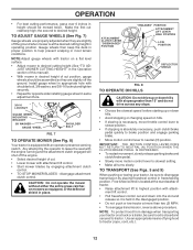
...ADJUST GAUGE WHEELS (See Fig. 7) Gauge wheels are properly adjusted when they are slightly off the ground. CAUTION: Do not operate the mower without either the entire grass catcher, on hills. • If slowing is necessary, move motion control lever to help prevent scalping in... opposite side installing gauge wheel in same adjustment hole. 3/8-16 LOCKNUT GUAGE WHEEL MOUNTING BRACKET 3/8 WASHER GAUGE WHEEL SHOULDER BOLT FIG. 7 TO OPERATE MOWER (See Fig. 8) Your tractor is equipped with tractor on a truck or a trailer, be sure to desired height. ATTACHMENT CLUTCH LEVER "DISENGAGED"...
...ADJUST GAUGE WHEELS (See Fig. 7) Gauge wheels are properly adjusted when they are slightly off the ground. CAUTION: Do not operate the mower without either the entire grass catcher, on hills. • If slowing is necessary, move motion control lever to help prevent scalping in... opposite side installing gauge wheel in same adjustment hole. 3/8-16 LOCKNUT GUAGE WHEEL MOUNTING BRACKET 3/8 WASHER GAUGE WHEEL SHOULDER BOLT FIG. 7 TO OPERATE MOWER (See Fig. 8) Your tractor is equipped with tractor on a truck or a trailer, be sure to desired height. ATTACHMENT CLUTCH LEVER "DISENGAGED"...
User Manual
Page 14
... the cut desired. • When operating attachments, select a ground speed that has been cut relatively high; This procedure will plug mower and leave undesirable clumps. Repeat this procedure there will result in neutral (N) position, slowly disengage clutch/brake pedal. • Move ...; Drive so that clippings are discharged onto the area that will discharge away from shrubs, fences, driveways, etc. See "TO LEVEL MOWER HOUSING" in neutral (N) position, slowly disengage clutch/brake pedal. • Slowly move motion control lever forward, after the tractor moves approximately...
... the cut desired. • When operating attachments, select a ground speed that has been cut relatively high; This procedure will plug mower and leave undesirable clumps. Repeat this procedure there will result in neutral (N) position, slowly disengage clutch/brake pedal. • Move ...; Drive so that clippings are discharged onto the area that will discharge away from shrubs, fences, driveways, etc. See "TO LEVEL MOWER HOUSING" in neutral (N) position, slowly disengage clutch/brake pedal. • Slowly move motion control lever forward, after the tractor moves approximately...

User Manual
Page 15
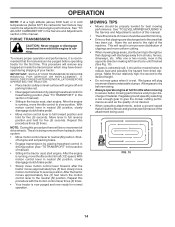
... the mulching action. This will biodegrade quickly to west the next week. MAX 1/3 FIG. 11 15 OPERATION MULCHING MOWING TIPS IMPORTANT: FOR BEST PERFORMANCE, KEEP MOWER HOUSING FREE OF BUILT-UP GRASS AND TRASH. Wet grass tends to completely hide the clippings. When doing a second cut, mow across or perpendicular to... grass clippings many times and reduce them in size so that an area be exposed to the direct sun. • For best results, adjust the mower cutting height so that the mower cuts off only the top one week then change to east to provide nutrients for the lawn.
... the mulching action. This will biodegrade quickly to west the next week. MAX 1/3 FIG. 11 15 OPERATION MULCHING MOWING TIPS IMPORTANT: FOR BEST PERFORMANCE, KEEP MOWER HOUSING FREE OF BUILT-UP GRASS AND TRASH. Wet grass tends to completely hide the clippings. When doing a second cut, mow across or perpendicular to... grass clippings many times and reduce them in size so that an area be exposed to the direct sun. • For best results, adjust the mower cutting height so that the mower cuts off only the top one week then change to east to provide nutrients for the lawn.
User Manual
Page 16
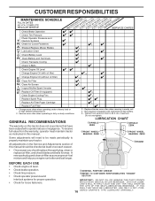
... IN DATES AS YOU COMPLETE REGULAR SERVICE Check Brake Operation Check Tire Pressure Check Operator Presence and T Interlock Systems R Check for Loose Fasteners A Sharpen/Replace Mower Blades C T Lubrication Chart 0 Check Battery Level R Clean Battery and Terminals Check Transaxle Cooling Check V-Belts BEFOREEEVAECRHYU8ESVHEEORUYRS2E5VHEROYUR5E0SVEHROYUR1E0SV0EHROYUBSREESFAOSROENSSTEORRAVGEICE DATES 5 3 4 Check Engine Oil Level Change Engine Oil (with...
... IN DATES AS YOU COMPLETE REGULAR SERVICE Check Brake Operation Check Tire Pressure Check Operator Presence and T Interlock Systems R Check for Loose Fasteners A Sharpen/Replace Mower Blades C T Lubrication Chart 0 Check Battery Level R Clean Battery and Terminals Check Transaxle Cooling Check V-Belts BEFOREEEVAECRHYU8ESVHEEORUYRS2E5VHEROYUR5E0SVEHROYUR1E0SV0EHROYUBSREESFAOSROENSSTEORRAVGEICE DATES 5 3 4 Check Engine Oil Level Change Engine Oil (with...
User Manual
Page 17
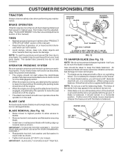
... eventual damage to keep the blade balanced. torque). The lobes of the center hole may appear to be sharpened with a file or on the mower. • To check blade balance, you do not recommend sharpening blade - TIRES • Maintain proper air pressure in all tires (See "PRODUCT...damage. Tire sealant also prevents tire dry rot and corrosion. NOTE: Do not use a nail for balancing blade. BLADE CARE For best results mower blades must be kept sharp. BRAKE OPERATION If tractor requires more than six (6) feet stopping distance at high speed in the disengaged position. &#...
... eventual damage to keep the blade balanced. torque). The lobes of the center hole may appear to be sharpened with a file or on the mower. • To check blade balance, you do not recommend sharpening blade - TIRES • Maintain proper air pressure in all tires (See "PRODUCT...damage. Tire sealant also prevents tire dry rot and corrosion. NOTE: Do not use a nail for balancing blade. BLADE CARE For best results mower blades must be kept sharp. BRAKE OPERATION If tractor requires more than six (6) feet stopping distance at high speed in the disengaged position. &#...
User Manual
Page 20
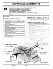
...spark plug wire from spark plug and place wire where it cannot come in "DISENGAGED" position. • Move attachment lift lever forward to lower mower to its lowest position. • Roll belt off engine pulley. • Remove small retainer spring, and lift clutch spring off pulley bolt....of bracket. • Disconnect anti-swaybar from chassis bracket by removing retainer springs. • Raise lift lever to raise suspension arms. Slide mower out from under tractor with deflector shield to right side of tractor. • Place attachment clutch in contact with retainer springs. • ...
...spark plug wire from spark plug and place wire where it cannot come in "DISENGAGED" position. • Move attachment lift lever forward to lower mower to its lowest position. • Roll belt off engine pulley. • Remove small retainer spring, and lift clutch spring off pulley bolt....of bracket. • Disconnect anti-swaybar from chassis bracket by removing retainer springs. • Raise lift lever to raise suspension arms. Slide mower out from under tractor with deflector shield to right side of tractor. • Place attachment clutch in contact with retainer springs. • ...

User Manual
Page 21
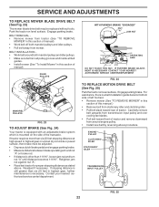
... any necessary adjustments, check that both front links are equal in length. • If links are not equal in length, adjust one side of mower, loosen lift link adjustment nut on both front links. Tighten nut "E" on both front links an equal number of turns. • When distance ...of tractor. Distance "A" on level ground or driveway. Measure distance "D" directly in its highest position. • At the midpoint of both sides of mower, measure height from trunnion on that side. MANDREL "D" "D" FIG. 21 BOTH FRONT LINKS MUST BE EQUAL IN LENGTH SUSPENSION ARM LIFT LINK ADJUSTMENT ...
... any necessary adjustments, check that both front links are equal in length. • If links are not equal in length, adjust one side of mower, loosen lift link adjustment nut on both front links. Tighten nut "E" on both front links an equal number of turns. • When distance ...of tractor. Distance "A" on level ground or driveway. Measure distance "D" directly in its highest position. • At the midpoint of both sides of mower, measure height from trunnion on that side. MANDREL "D" "D" FIG. 21 BOTH FRONT LINKS MUST BE EQUAL IN LENGTH SUSPENSION ARM LIFT LINK ADJUSTMENT ...
User Manual
Page 22
...If distance is other than 1-9/16", loosen jam nut and turn nut "A" until distance becomes 1-9/16". BELT REMOVAL • Remove mower from tractor (See "TO REMOVE MOWER" in this section of manual). Readjust if necessary. Park the tractor on level surface. Engage parking brake. BELT INSTALLATION • ... pulleys and idler pulleys. • Make sure belt is in all pulley grooves and inside all belt guides. • Install mower (See "To Install Mower" in highest gear, further maintenance is mounted on a level dry concrete or paved surface, then brake must be replaced without tools...
...If distance is other than 1-9/16", loosen jam nut and turn nut "A" until distance becomes 1-9/16". BELT REMOVAL • Remove mower from tractor (See "TO REMOVE MOWER" in this section of manual). Readjust if necessary. Park the tractor on level surface. Engage parking brake. BELT INSTALLATION • ... pulleys and idler pulleys. • Make sure belt is in all pulley grooves and inside all belt guides. • Install mower (See "To Install Mower" in highest gear, further maintenance is mounted on a level dry concrete or paved surface, then brake must be replaced without tools...

User Manual
Page 23
... corrosion. SERVICE AND ADJUSTMENTS TRANSMISSION REMOVAL/REPLACEMENT Should your transmission require removal for service or replacement, it is needed to get to adjustment bolt, move mower deck height to slow leaks, tire sealant may be purchased from your nearest authorized service center/department. NOTE: If additional clearance is trying to right...
... corrosion. SERVICE AND ADJUSTMENTS TRANSMISSION REMOVAL/REPLACEMENT Should your transmission require removal for service or replacement, it is needed to get to adjustment bolt, move mower deck height to slow leaks, tire sealant may be purchased from your nearest authorized service center/department. NOTE: If additional clearance is trying to right...
User Manual
Page 26
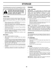
...your tractor with new spark plug(s). Plastic cannot breathe which allows condensation to form and will cause your tractor to reach the carburetor. When mower is to "START" position for storage, do not store battery directly on stabilizer container. Replace if necessary. • Touch up all ...nuts, bolts and screws are empty. • Never use plastic. TRACTOR Remove mower from tractor for a few seconds to gasoline in any enclosure. NOTE: Fuel stabilizer is removed from tractor for 30 days or more. Add ...
...your tractor with new spark plug(s). Plastic cannot breathe which allows condensation to form and will cause your tractor to reach the carburetor. When mower is to "START" position for storage, do not store battery directly on stabilizer container. Replace if necessary. • Touch up all ...nuts, bolts and screws are empty. • Never use plastic. TRACTOR Remove mower from tractor for a few seconds to gasoline in any enclosure. NOTE: Fuel stabilizer is removed from tractor for 30 days or more. Add ...

User Manual
Page 27
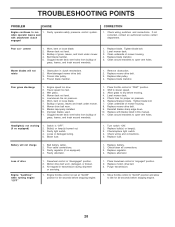
... 6. See "To Adjust Carburetor" in Service Adjustments section. 8. Dirty air filter. 2. Dirty fuel filter. 5. Engine valves out of mower housing. 4. Drain fuel tank and refill with fresh gasoline and replace fuel filter. 8. See "To Adjust Carburetor" in Service Adjustments section...or dead battery. 4. Engine will not start CAUSE 1. Blown fuse. 5. Check/replace ignition switch. 8. Loss of grass, leaves and trash under mower. 4. Build-up of power 1. Dirty air filter. 5. Faulty spark plug. 7. Clean and regap or change oil. 6. Contact an authorized ...
... 6. See "To Adjust Carburetor" in Service Adjustments section. 8. Dirty air filter. 2. Dirty fuel filter. 5. Engine valves out of mower housing. 4. Drain fuel tank and refill with fresh gasoline and replace fuel filter. 8. See "To Adjust Carburetor" in Service Adjustments section...or dead battery. 4. Engine will not start CAUSE 1. Blown fuse. 5. Check/replace ignition switch. 8. Loss of grass, leaves and trash under mower. 4. Build-up of power 1. Dirty air filter. 5. Faulty spark plug. 7. Clean and regap or change oil. 6. Contact an authorized ...
User Manual
Page 28
...in "disengaged" position. 2. If not corrected, contact an authorized service center/ department. Worn, bent or loose blade. 2. Level mower deck. 3. Clean around mandrels. 1. Frozen idler pulley. 4. Remove obstruction. 2. Blades improperly installed. 10. Improper blades used. ... 11. Place freewheel control in clutch mechanism. 2. Replace motion drive belt. 3. Tighten blade bolt. 2. Clean underside of mower housing. 8. Replace blade mandrel. Mower deck not level. 5. Tighten blade bolt. 7. Bulb(s) or lamp(s) burned out. 3. Check/replace light switch. 4....
...in "disengaged" position. 2. If not corrected, contact an authorized service center/ department. Worn, bent or loose blade. 2. Level mower deck. 3. Clean around mandrels. 1. Frozen idler pulley. 4. Remove obstruction. 2. Blades improperly installed. 10. Improper blades used. ... 11. Place freewheel control in clutch mechanism. 2. Replace motion drive belt. 3. Tighten blade bolt. 2. Clean underside of mower housing. 8. Replace blade mandrel. Mower deck not level. 5. Tighten blade bolt. 7. Bulb(s) or lamp(s) burned out. 3. Check/replace light switch. 4....

User Manual
Page 33
... Lh 34 179717X428 Footrest Pnt Rh 35 72110606 Bolt Rdhd Sht Sqnk 3/8-16 x 3/4 37 17490508 Screw Thdrol 6/16-18 x 1/2 TYT 38 175710 Bracket Asm Pivot Mower Rear 51 73800400 Nut Lock Hex W/Ins 1/4-20 52 19091416 Washer 9/32 x 7/8 x 16 Ga. 53 144697 Bracjet Grukke Lh 54 161464 Screw Hex Wshd 8-18... Thdrol 3/8-16 x 1/2 212 156229 Insert Lens Relect 219 17000512 Screw 5/16-18 x 3/4 NOTE: All component dimensions given in U.S. inches 1 inch = 25.4 mm 33 MODEL NUMBER PR185H42STE KEY PART NO.
... Lh 34 179717X428 Footrest Pnt Rh 35 72110606 Bolt Rdhd Sht Sqnk 3/8-16 x 3/4 37 17490508 Screw Thdrol 6/16-18 x 1/2 TYT 38 175710 Bracket Asm Pivot Mower Rear 51 73800400 Nut Lock Hex W/Ins 1/4-20 52 19091416 Washer 9/32 x 7/8 x 16 Ga. 53 144697 Bracjet Grukke Lh 54 161464 Screw Hex Wshd 8-18... Thdrol 3/8-16 x 1/2 212 156229 Insert Lens Relect 219 17000512 Screw 5/16-18 x 3/4 NOTE: All component dimensions given in U.S. inches 1 inch = 25.4 mm 33 MODEL NUMBER PR185H42STE KEY PART NO.
User Manual
Page 39
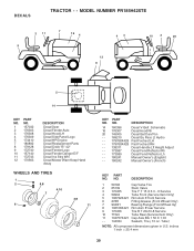
... (Service Item Only) 11 104757X421 Cap Axle Blk 1 50 X 1 00 - - 144334 Sealant, Tire ( 10 oz. inches 1 inch = 25.4 mm 39 NO. DECALS TRACTOR - - MODEL NUMBER PR185H42STE 2 11 7 16 4 9 43 12 8 10 2 20 1 5 14 KEY NO. 1 2 3 4 5 7 8 9 10 11 12 PART NO. 157032 176303 176308 176309 174410 180892 179128...Logo Decal HP Engine Decal Replacement Parts Decal Deck "B" 42" Decal Fender Logo Decal Fender Danger E/F Decal Ins Strg Whl Decal Mower Warn Keep Hand Away WHEELS AND TIRES 1 2 5,8 4,10 7 6 3,9 11 KEY PART NO. Tube) NOTE: All component dimensions given in U.S. NO...
... (Service Item Only) 11 104757X421 Cap Axle Blk 1 50 X 1 00 - - 144334 Sealant, Tire ( 10 oz. inches 1 inch = 25.4 mm 39 NO. DECALS TRACTOR - - MODEL NUMBER PR185H42STE 2 11 7 16 4 9 43 12 8 10 2 20 1 5 14 KEY NO. 1 2 3 4 5 7 8 9 10 11 12 PART NO. 157032 176303 176308 176309 174410 180892 179128...Logo Decal HP Engine Decal Replacement Parts Decal Deck "B" 42" Decal Fender Logo Decal Fender Danger E/F Decal Ins Strg Whl Decal Mower Warn Keep Hand Away WHEELS AND TIRES 1 2 5,8 4,10 7 6 3,9 11 KEY PART NO. Tube) NOTE: All component dimensions given in U.S. NO...


