
User Manual
Page 2
...be picked up . SAFETY RULES Safe Operation Practices for wheel weights or counterweights to improve stability. • Use extra care with manufacturer's recommended parts, when necessary. • Mower blades are subject to wear, damage, and deterioration, which can result in a large percentage of the mower... low gear so that may fall off and be thrown. Do not make adjustments or repairs with safety devices. Reduced traction could expose moving parts or allow children to the presence of the machine. • Keep all instructions in place. • Slow down slopes, not across. ...
...be picked up . SAFETY RULES Safe Operation Practices for wheel weights or counterweights to improve stability. • Use extra care with manufacturer's recommended parts, when necessary. • Mower blades are subject to wear, damage, and deterioration, which can result in a large percentage of the mower... low gear so that may fall off and be thrown. Do not make adjustments or repairs with safety devices. Reduced traction could expose moving parts or allow children to the presence of the machine. • Keep all instructions in place. • Slow down slopes, not across. ...

User Manual
Page 4
... tools to service or repair this manual). TRACTOR 30-45 WARRANTY 46 4 A spark arrester for and using your nearest authorized service center/department (See REPAIR PARTS section of this manual. LBS. CCA: 240 CASE SIZE: U1R BLADE BOLT TORQUE: 27-35 FT. The instructions will enable you to give you cannot... SAFETY RULES 2-3 PRODUCT SPECIFICATIONS 4 CUSTOMER RESPONSIBILITIES 4, 16-19 ASSEMBLY 6-8 OPERATION 9-15 MAINTENANCE SCHEDULE 16 SERVICE AND ADJUSTMENTS 20-25 STORAGE 26 TROUBLESHOOTING 27-28 REPAIR PARTS -
... tools to service or repair this manual). TRACTOR 30-45 WARRANTY 46 4 A spark arrester for and using your nearest authorized service center/department (See REPAIR PARTS section of this manual. LBS. CCA: 240 CASE SIZE: U1R BLADE BOLT TORQUE: 27-35 FT. The instructions will enable you to give you cannot... SAFETY RULES 2-3 PRODUCT SPECIFICATIONS 4 CUSTOMER RESPONSIBILITIES 4, 16-19 ASSEMBLY 6-8 OPERATION 9-15 MAINTENANCE SCHEDULE 16 SERVICE AND ADJUSTMENTS 20-25 STORAGE 26 TROUBLESHOOTING 27-28 REPAIR PARTS -

User Manual
Page 5
UNASSEMBLED PARTS Steering Wheel Seat Steering Sleeve Steering Wheel Insert Steering Extension Shaft (1) Hex Bolt 3/8-16 x 1 Steering Adapter (1) Large Flat Washer (1) Washer 17/32 x 1-3/16 x 12 Gauge (1) Knob (1) Oil Drain Tube For Future Use Slope Sheet (1) Lock washer 3/8 (1) Locknut 5/16-18 (1) Hex Bolt 5/16-18 x 1-1/4 (2) Mulch Blades 5 (2) Keys
UNASSEMBLED PARTS Steering Wheel Seat Steering Sleeve Steering Wheel Insert Steering Extension Shaft (1) Hex Bolt 3/8-16 x 1 Steering Adapter (1) Large Flat Washer (1) Washer 17/32 x 1-3/16 x 12 Gauge (1) Knob (1) Oil Drain Tube For Future Use Slope Sheet (1) Lock washer 3/8 (1) Locknut 5/16-18 (1) Hex Bolt 5/16-18 x 1-1/4 (2) Mulch Blades 5 (2) Keys

User Manual
Page 6
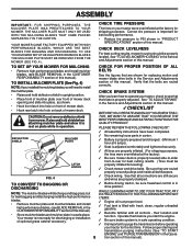
...wrench sizes are listed. INSERT 3/8 HEX BOLT 3/8 LOCK WASHER LARGE FLAT WASHER TO REMOVE TRACTOR FROM CARTON UNPACK CARTON • Remove all parts and hardware you are in the operating position (seated behind the steering wheel). Align mounting holes in dash and push down to bottom, along... lines on label (label located between terminals) charge battery for minimum of one hour at the factory with exception of those parts left hand is put into center of steering wheel. • Remove protective materials from top to secure. STEERING WHEEL STEERING BOOT TABS BEFORE...
...wrench sizes are listed. INSERT 3/8 HEX BOLT 3/8 LOCK WASHER LARGE FLAT WASHER TO REMOVE TRACTOR FROM CARTON UNPACK CARTON • Remove all parts and hardware you are in the operating position (seated behind the steering wheel). Align mounting holes in dash and push down to bottom, along... lines on label (label located between terminals) charge battery for minimum of one hour at the factory with exception of those parts left hand is put into center of steering wheel. • Remove protective materials from top to secure. STEERING WHEEL STEERING BOOT TABS BEFORE...
User Manual
Page 8
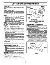
.... • Hook front latch into hole on front of optional grass catcher accessory. DEFLECTOR SHIELD MULCHER PLATE PLEASE REVIEW THE FOLLOWING CHECKLIST: ! No remaining loose parts in drive position. Seat is filled with all belt keepers. ! Check mower and drive belts. Your mower is in carton. ! Before driving tractor, be sure...
.... • Hook front latch into hole on front of optional grass catcher accessory. DEFLECTOR SHIELD MULCHER PLATE PLEASE REVIEW THE FOLLOWING CHECKLIST: ! No remaining loose parts in drive position. Seat is filled with all belt keepers. ! Check mower and drive belts. Your mower is in carton. ! Before driving tractor, be sure...
User Manual
Page 17
... is fully depressed and attachement clutch control is in exact order as shown. TIRES • Maintain proper air pressure in a horizontal position. If your local parts dealer. Replace bent or damaged blades. BLADE REMOVAL (See Fig. 12) • Raise mower to highest position to allow access to leave the seat should...
... is fully depressed and attachement clutch control is in exact order as shown. TIRES • Maintain proper air pressure in a horizontal position. If your local parts dealer. Replace bent or damaged blades. BLADE REMOVAL (See Fig. 12) • Raise mower to highest position to allow access to leave the seat should...
User Manual
Page 20
TO INSTALL MOWER (See Fig. 18) • Raise attachment lift lever to its highest position. • Slide mower under tractor with plug. moving parts have completely stopped. • Disconnect spark plug wire from spark plug and place wire where it cannot come in reverse order of removal instructions. TO ...
TO INSTALL MOWER (See Fig. 18) • Raise attachment lift lever to its highest position. • Slide mower under tractor with plug. moving parts have completely stopped. • Disconnect spark plug wire from spark plug and place wire where it cannot come in reverse order of removal instructions. TO ...

User Manual
Page 23
After above steps until satisfied. If damage has occurred to affect the front wheel toein or camber, contact your local parts dealer. Insert square key. • Replace washers and snap retaining ring securely in rear wheel hub and axle. NOTE: If additional clearance is needed to ...
After above steps until satisfied. If damage has occurred to affect the front wheel toein or camber, contact your local parts dealer. Insert square key. • Replace washers and snap retaining ring securely in rear wheel hub and axle. NOTE: If additional clearance is needed to ...

User Manual
Page 25
...; Check that swivel is against stop . See electrical wiring diagram in fuse. TO REPLACE FUSE Replace with 20 amp automotive-type plug-in the Repair Parts section. Tighten casing clamp screw securely. • Replace air cleaner cover assembly and tighten knob. OVERSPEEDING THE ENGINE ABOVE THE FACTORY HIGH SPEED SETTING CAN...
...; Check that swivel is against stop . See electrical wiring diagram in fuse. TO REPLACE FUSE Replace with 20 amp automotive-type plug-in the Repair Parts section. Tighten casing clamp screw securely. • Replace air cleaner cover assembly and tighten knob. OVERSPEEDING THE ENGINE ABOVE THE FACTORY HIGH SPEED SETTING CAN...

User Manual
Page 26
When mower is removed from one ounce of this manual. • Be sure that does not retain moisture. Inspect moving parts for a few seconds to gasoline in the fuel tank or permanent damage may reach an open flame or spark. ENGINE FUEL SYSTEM IMPORTANT: IT IS ...IMPORTANT TO PREVENT GUM DEPOSITS FROM FORMING IN ESSENTIAL FUEL SYSTEM PARTS SUCH AS CARBURETOR, FUEL FILTER, FUEL HOSE, OR TANK DURING STORAGE. NOTE: Fuel stabilizer is an acceptable alternative in minimizing the formation of fuel gum...
When mower is removed from one ounce of this manual. • Be sure that does not retain moisture. Inspect moving parts for a few seconds to gasoline in the fuel tank or permanent damage may reach an open flame or spark. ENGINE FUEL SYSTEM IMPORTANT: IT IS ...IMPORTANT TO PREVENT GUM DEPOSITS FROM FORMING IN ESSENTIAL FUEL SYSTEM PARTS SUCH AS CARBURETOR, FUEL FILTER, FUEL HOSE, OR TANK DURING STORAGE. NOTE: Fuel stabilizer is an acceptable alternative in minimizing the formation of fuel gum...

User Manual
Page 27
... Dirty/clogged muffler. 13. Check oil level/change spark plug. 7. Connect and tighten spark plug wire. 11. Replace blade. Tighten loose part(s). Stale or dirty fuel. 6. Engine valves out of adjustment. 8. Replace spark plug. 3. Check all wiring. 9. See "To Adjust Carburetor...Stale or dirty fuel. 9. Dirty engine air screen/fins. 12. Clean/replace muffler. 13. Contact an authorized service center/department. Loose/damaged part(s). 1. Replace blade mandrel. 3. Engine not "CHOKED" properly. 3. See "TO START ENGINE" in "Higher Cut" position/reduce speed. ...
... Dirty/clogged muffler. 13. Check oil level/change spark plug. 7. Connect and tighten spark plug wire. 11. Replace blade. Tighten loose part(s). Stale or dirty fuel. 6. Engine valves out of adjustment. 8. Replace spark plug. 3. Check all wiring. 9. See "To Adjust Carburetor...Stale or dirty fuel. 9. Dirty engine air screen/fins. 12. Clean/replace muffler. 13. Contact an authorized service center/department. Loose/damaged part(s). 1. Replace blade mandrel. 3. Engine not "CHOKED" properly. 3. See "TO START ENGINE" in "Higher Cut" position/reduce speed. ...

User Manual
Page 31
inches 1 inch = 25.4 mm 31 ELECTRICAL TRACTOR - - MODEL NUMBER PR185H42STD KEY NO. 1 2 8 16 21 22 24 25 26 27 28 29 30 33 40 41 42 43 45 52 PART NO. 163465 74760412 156417 153664 166181 4152J 4799J 146147 175158 73510400 4207J 121305X 175566 140401 170217 71110408 131563 175141 121433X 141940 DESCRIPTION Battery...
inches 1 inch = 25.4 mm 31 ELECTRICAL TRACTOR - - MODEL NUMBER PR185H42STD KEY NO. 1 2 8 16 21 22 24 25 26 27 28 29 30 33 40 41 42 43 45 52 PART NO. 163465 74760412 156417 153664 166181 4152J 4799J 146147 175158 73510400 4207J 121305X 175566 140401 170217 71110408 131563 175141 121433X 141940 DESCRIPTION Battery...
User Manual
Page 33
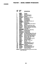
MODEL NUMBER PR185H42STD KEY PART NO. CHASSIS TRACTOR - - NO. DESCRIPTION 1 174619 Chassis 2 176554 Drawbar 3 17060612 Screw 3/8-16 X .75 5 155272 Bumper Hood/Dash 9 168337X012 Dash P/L 10 72140608 Bolt Carriage 3/8-16 x 1 11 ...
MODEL NUMBER PR185H42STD KEY PART NO. CHASSIS TRACTOR - - NO. DESCRIPTION 1 174619 Chassis 2 176554 Drawbar 3 17060612 Screw 3/8-16 X .75 5 155272 Bumper Hood/Dash 9 168337X012 Dash P/L 10 72140608 Bolt Carriage 3/8-16 x 1 11 ...
User Manual
Page 35
...3/8-16 x 1.0 V-Belt, Ground Drive Keeper, Center Span Screw Thdrol. 3/8-16 x .75 Cover, Pedal Pulley, Engine KEY PART NO. Cross Hydro 82 123782X Spring Torsion T/A 83 19171216 Washer 17/32 x 3/4 x 16 Ga. 84 169594 Link Transaxle...56 17060616 57 140294 59 169691 61 17060612 62 8883R 63 175410 DESCRIPTION Transaxle Hydro Gear 314-0510 (Order Parts From Transaxle Manufacturer) Rod Shift Hydro LT Pin Cotter 1/8 x 1 CAD Washer Lock Hvy Helical Bolt, ... 25/32 x 1-5/8 x 16 Gauge 81 165596 Shaft Asm. MODEL NUMBER PR185H42STD KEY PART NO. DRIVE TRACTOR - - NO. inches 1 inch = 25.4 mm 35
...3/8-16 x 1.0 V-Belt, Ground Drive Keeper, Center Span Screw Thdrol. 3/8-16 x .75 Cover, Pedal Pulley, Engine KEY PART NO. Cross Hydro 82 123782X Spring Torsion T/A 83 19171216 Washer 17/32 x 3/4 x 16 Ga. 84 169594 Link Transaxle...56 17060616 57 140294 59 169691 61 17060612 62 8883R 63 175410 DESCRIPTION Transaxle Hydro Gear 314-0510 (Order Parts From Transaxle Manufacturer) Rod Shift Hydro LT Pin Cotter 1/8 x 1 CAD Washer Lock Hvy Helical Bolt, ... 25/32 x 1-5/8 x 16 Gauge 81 165596 Shaft Asm. MODEL NUMBER PR185H42STD KEY PART NO. DRIVE TRACTOR - - NO. inches 1 inch = 25.4 mm 35

User Manual
Page 37
... 87 173966 Washer Flat .781 x 1-1/2 x .14 88 175118 Bolt Shoulder 7/16-20 Unc 91 175553 Clip Steering NOTE: All component dimensions given in U.S. MODEL NUMBER PR185H42STD STEERING ASSEMBLY KEY PART NO. TRACTOR - -
... 87 173966 Washer Flat .781 x 1-1/2 x .14 88 175118 Bolt Shoulder 7/16-20 Unc 91 175553 Clip Steering NOTE: All component dimensions given in U.S. MODEL NUMBER PR185H42STD STEERING ASSEMBLY KEY PART NO. TRACTOR - -

User Manual
Page 38
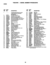
... Washer 13/32 X 1 X 14 Ga. Bolt Shoulder 5/16-18 X 62 NOTE: All component dimensions given in U.S. TRACTOR - - Pan Seat Knob Seat Bracket Mounting Switch KEY PART NO. inches 1 inch = 25.4 mm 38 MODEL NUMBER PR185H42STD SEAT ASSEMBLY 1 14 24 8 9 7 10 5 8 9 7 5 6 22 2 21 16 25 15 11 4 13 17 12 3 KEY...
... Washer 13/32 X 1 X 14 Ga. Bolt Shoulder 5/16-18 X 62 NOTE: All component dimensions given in U.S. TRACTOR - - Pan Seat Knob Seat Bracket Mounting Switch KEY PART NO. inches 1 inch = 25.4 mm 38 MODEL NUMBER PR185H42STD SEAT ASSEMBLY 1 14 24 8 9 7 10 5 8 9 7 5 6 22 2 21 16 25 15 11 4 13 17 12 3 KEY...

User Manual
Page 39
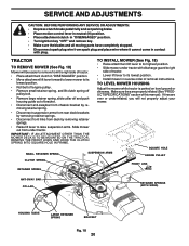
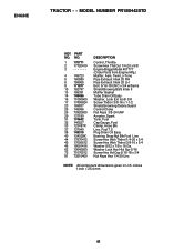
MODEL NUMBER PR185H42STD 2 11 9 6 16 4 43 8 10 2 20 1 5 14 KEY NO. 1 2 3 4 5 6 8 PART NO. 157032 176303 176308 176309 174410 169210 170563 9 172740 10 157140 DESCRIPTION Decal Oper Decal Fender Auto Decal Hood LH Decal Side Panel Logo ... HP Engine Decal By Pass Lt Hydro Decal Mower Warn Keep Hand Away Decal Fender Logo Decal Fender Danger E/F WHEELS AND TIRES 1 2 5,8 4,10 7 3,9 6 11 KEY PART NO. DESCRIPTION 1 59192 Cap Valve Tire 2 65139 Stem Valve 3 170455 Tire F T 15 X 6 0 - 6 Service 4 59904 Tube Front (Service Item Only) 5 106732X421 Rim Asm 6"front Service 6...
MODEL NUMBER PR185H42STD 2 11 9 6 16 4 43 8 10 2 20 1 5 14 KEY NO. 1 2 3 4 5 6 8 PART NO. 157032 176303 176308 176309 174410 169210 170563 9 172740 10 157140 DESCRIPTION Decal Oper Decal Fender Auto Decal Hood LH Decal Side Panel Logo ... HP Engine Decal By Pass Lt Hydro Decal Mower Warn Keep Hand Away Decal Fender Logo Decal Fender Danger E/F WHEELS AND TIRES 1 2 5,8 4,10 7 3,9 6 11 KEY PART NO. DESCRIPTION 1 59192 Cap Valve Tire 2 65139 Stem Valve 3 170455 Tire F T 15 X 6 0 - 6 Service 4 59904 Tube Front (Service Item Only) 5 106732X421 Rim Asm 6"front Service 6...
User Manual
Page 41
...44 17670412 45 17000612 46 19091416 62 10040500 72 71070512 81 73510400 DESCRIPTION Control, Throttle Screw Hex Thd Cut 1/4-20 x 5/8 Engine Briggs Model 407777 (Order Parts from Engine Mfg.) Muffler, Asm. Washer Lock Hvy Hlcl Spr 5/16 Screw Hex Hd Cap 5/16-18 x 3/4 Nut Keps Hex 1/4-20 Unc NOTE...: All component dimensions given in U.S. inches 1 inch = 25.4 mm 41 MODEL NUMBER PR185H42STD KEY PART NO. ENGINE TRACTOR - - Twin Lo-Tone Pipe Exhaust Intek 20 RH Pipe Exhaust Intek 20 LH Bolt 5/16-18 UNC x 3/4 w/Sems Shield Browing B&S ...
...44 17670412 45 17000612 46 19091416 62 10040500 72 71070512 81 73510400 DESCRIPTION Control, Throttle Screw Hex Thd Cut 1/4-20 x 5/8 Engine Briggs Model 407777 (Order Parts from Engine Mfg.) Muffler, Asm. Washer Lock Hvy Hlcl Spr 5/16 Screw Hex Hd Cap 5/16-18 x 3/4 Nut Keps Hex 1/4-20 Unc NOTE...: All component dimensions given in U.S. inches 1 inch = 25.4 mm 41 MODEL NUMBER PR185H42STD KEY PART NO. ENGINE TRACTOR - - Twin Lo-Tone Pipe Exhaust Intek 20 RH Pipe Exhaust Intek 20 LH Bolt 5/16-18 UNC x 3/4 w/Sems Shield Browing B&S ...

User Manual
Page 43
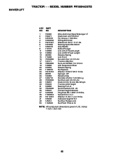
MODEL NUMBER PR185H42STD KEY NO. 1 2 3 4 5 6 8 9 10 11 13 14 15 16 18 19 20 21 22 23 24 25 26 27 28 29 30 31 32 33 34 35 36 37 40 44 45 46 48 49 50 51 52 53 54 55 56 59 PART NO. DESCRIPTION 165892X421 72140506 138017 ... Bolt Rdhd Sqn 3/8-16 UNC x 1-3/4 Mandrel Assembly (Includes Key Numbers 8-10,13-15, 31 and 33) Mower Deck, Complete NOTE: All component dimensions given in U.S. PART NO. 171598 144959 74760616 132274 73800600 19171416 132264 132273 136420 71081010 19061216 10071000 160793 2029J 155197X421 155198X421 17060514 73510500 72110504 4898H 165746 73930600 19121414 173986...
MODEL NUMBER PR185H42STD KEY NO. 1 2 3 4 5 6 8 9 10 11 13 14 15 16 18 19 20 21 22 23 24 25 26 27 28 29 30 31 32 33 34 35 36 37 40 44 45 46 48 49 50 51 52 53 54 55 56 59 PART NO. DESCRIPTION 165892X421 72140506 138017 ... Bolt Rdhd Sqn 3/8-16 UNC x 1-3/4 Mandrel Assembly (Includes Key Numbers 8-10,13-15, 31 and 33) Mower Deck, Complete NOTE: All component dimensions given in U.S. PART NO. 171598 144959 74760616 132274 73800600 19171416 132264 132273 136420 71081010 19061216 10071000 160793 2029J 155197X421 155198X421 17060514 73510500 72110504 4898H 165746 73930600 19121414 173986...
User Manual
Page 45
MODEL NUMBER PR185H42STD KEY PART NO. NO. DESCRIPTION 1 159460 2 159471 3 105767X 4 12000002 5 19211621 6 120183X 7 125631X 8 170770 11 139865 12 139866 13 4939M 15 173288 16 73350800 17 130171 18 73800800 ...
MODEL NUMBER PR185H42STD KEY PART NO. NO. DESCRIPTION 1 159460 2 159471 3 105767X 4 12000002 5 19211621 6 120183X 7 125631X 8 170770 11 139865 12 139866 13 4939M 15 173288 16 73350800 17 130171 18 73800800 ...


