

User Manual
Page 2
...Always look behind before mowing. Children are explosive. - Use only an approved container. - Check their ability to operate the riding mower safely enough to be seriously injured or interfere with grass catchers or other debris buildup. These operators should evaluate their proper operation regularly...8226; Use slow speed. They may obscure vision. II. Do not smoke. - SAFETY RULES SAFE OPERATION PRACTICES FOR RIDE-ON MOWERS IMPORTANT: THIS CUTTING MACHINE IS CAPABLE OF AMPUTATING HANDS AND FEET AND THROWING OBJECTS. GENERAL OPERATION • Read, understand, and ...
...Always look behind before mowing. Children are explosive. - Use only an approved container. - Check their ability to operate the riding mower safely enough to be seriously injured or interfere with grass catchers or other debris buildup. These operators should evaluate their proper operation regularly...8226; Use slow speed. They may obscure vision. II. Do not smoke. - SAFETY RULES SAFE OPERATION PRACTICES FOR RIDE-ON MOWERS IMPORTANT: THIS CUTTING MACHINE IS CAPABLE OF AMPUTATING HANDS AND FEET AND THROWING OBJECTS. GENERAL OPERATION • Read, understand, and ...
User Manual
Page 3
... of the mowing area and under the watchful care of California to point out important safety precautions. SAFETY RULES Safe Operation Practices for Ride-On Mowers • Be sure the area is dangerous. Always look behind before mowing. Uneven terrain could overturn the machine. CAUTION: In order to prevent accidental starting...
... of the mowing area and under the watchful care of California to point out important safety precautions. SAFETY RULES Safe Operation Practices for Ride-On Mowers • Be sure the area is dangerous. Always look behind before mowing. Uneven terrain could overturn the machine. CAUTION: In order to prevent accidental starting...

User Manual
Page 8
...with fresh, clean, regular unleaded gasoline. ! Raise and hold deflector shield in "PRODUCT SPECIFICATIONS" section of this manual. See "TO LEVEL MOWER HOUSING" in the Service and Adjustments section of this manual. CHECK BRAKE SYSTEM After you learn how to rest on back of this manual...amps). ! See that the belts are routed properly around pulleys and inside all controls - CAUTION: Do not remove deflector shield from mower. CHECK FOR PROPER POSITION OF ALL BELTS See the figures that the brake is adjusted comfortably and tightened securely. ! Check wiring. TO ...
...with fresh, clean, regular unleaded gasoline. ! Raise and hold deflector shield in "PRODUCT SPECIFICATIONS" section of this manual. See "TO LEVEL MOWER HOUSING" in the Service and Adjustments section of this manual. CHECK BRAKE SYSTEM After you learn how to rest on back of this manual...amps). ! See that the belts are routed properly around pulleys and inside all controls - CAUTION: Do not remove deflector shield from mower. CHECK FOR PROPER POSITION OF ALL BELTS See the figures that the brake is adjusted comfortably and tightened securely. ! Check wiring. TO ...

User Manual
Page 9
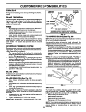
BATTERY CAUTION OR WARNING REVERSE FORWARD FAST SLOW ENGINE ON ENGINE OFF OIL PRESSURE LIGHTS ON OVER TEMP LIGHT FUEL CHOKE MOWER HEIGHT PARKING BRAKE LOCKED UNLOCKED MOWER LIFT ATTACHMENT REVERSE CLUTCH ENGAGED NEUTRAL HIGH LOW P PARKING BRAKE 15 15 15 IGNITION ATTACHMENT CLUTCH DISENGAGED KEEP AREA CLEAR SLOPE HAZARDS (SEE SAFETY RULES SECTION) DANGER, KEEP HANDS AND FEET AWAY 9 FREE WHEEL (Automatic Models only) Learn and understand their meaning. OPERATION These symbols may appear on your tractor or in literature supplied with the product.
BATTERY CAUTION OR WARNING REVERSE FORWARD FAST SLOW ENGINE ON ENGINE OFF OIL PRESSURE LIGHTS ON OVER TEMP LIGHT FUEL CHOKE MOWER HEIGHT PARKING BRAKE LOCKED UNLOCKED MOWER LIFT ATTACHMENT REVERSE CLUTCH ENGAGED NEUTRAL HIGH LOW P PARKING BRAKE 15 15 15 IGNITION ATTACHMENT CLUTCH DISENGAGED KEEP AREA CLEAR SLOPE HAZARDS (SEE SAFETY RULES SECTION) DANGER, KEEP HANDS AND FEET AWAY 9 FREE WHEEL (Automatic Models only) Learn and understand their meaning. OPERATION These symbols may appear on your tractor or in literature supplied with the product.

User Manual
Page 10
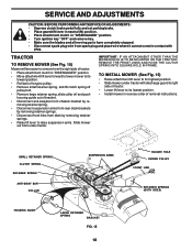
... BRAKE LEVER GEARSHIFT LEVER FIG. 5 Our tractors conform to your tractor. ATTACHMENT LIFT LEVER: Used to raise and lower the mower deck or other attachments mounted to your tractor. OPERATION KNOW YOUR TRACTOR READ THIS OWNER'S MANUAL AND SAFETY RULES BEFORE OPERATING YOUR... for future reference. AMMETER: Indicates charging (+) or discharging (-) of tractor. 10 HEIGHT ADJUSTMENT KNOB: Used to adjust the mower cutting height ATTACHMENT CLUTCH LEVER: Used to engage the mower blades, or other attachments mounted to the safety standards of various controls and adjustments.
... BRAKE LEVER GEARSHIFT LEVER FIG. 5 Our tractors conform to your tractor. ATTACHMENT LIFT LEVER: Used to raise and lower the mower deck or other attachments mounted to your tractor. OPERATION KNOW YOUR TRACTOR READ THIS OWNER'S MANUAL AND SAFETY RULES BEFORE OPERATING YOUR... for future reference. AMMETER: Indicates charging (+) or discharging (-) of tractor. 10 HEIGHT ADJUSTMENT KNOB: Used to adjust the mower cutting height ATTACHMENT CLUTCH LEVER: Used to engage the mower blades, or other attachments mounted to the safety standards of various controls and adjustments.

User Manual
Page 11
... pedal. CLUTCH/BRAKE PEDAL "DRIVE" POSITION HEIGHT ADJUSTMENT KNOB GEAR SHIFT LEVER PARKING BRAKE "DISENGAGED" POSITION FIG. 6 STOPPING (See Fig. 6) MOWER BLADES - • To stop engine. The cutting height range is running, any attempt by the operator to neutral (N) position. TO ADJUST GAUGE... 6) The cutting height is at less than full throttle reduces the battery charging rate. • Full throttle offers the best bagging and mower perfor- TO MOVE FORWARD AND BACKWARD (See Fig. 6) "BRAKE" POSITION PARKING BRAKE "ENGAGED" POSITION The direction and speed of movement ...
... pedal. CLUTCH/BRAKE PEDAL "DRIVE" POSITION HEIGHT ADJUSTMENT KNOB GEAR SHIFT LEVER PARKING BRAKE "DISENGAGED" POSITION FIG. 6 STOPPING (See Fig. 6) MOWER BLADES - • To stop engine. The cutting height range is running, any attempt by the operator to neutral (N) position. TO ADJUST GAUGE... 6) The cutting height is at less than full throttle reduces the battery charging rate. • Full throttle offers the best bagging and mower perfor- TO MOVE FORWARD AND BACKWARD (See Fig. 6) "BRAKE" POSITION PARKING BRAKE "ENGAGED" POSITION The direction and speed of movement ...

User Manual
Page 12
... storage. Install gauge wheel in same adjustment hole. 3/8-16 LOCKNUT GAUGE WHEEL MOUNTING BRACKET 3/8 WASHER GAUGE WHEEL FIG. 6B SHOULDER BOLT TO OPERATE MOWER (See Fig. 7) Your tractor is dangerous. disengage attachment clutch control. Use common sense when towing. Do not overfill. • For cold ... wait for easier starting up or down fuel system should change engine oil, see the Customer Responsibilities section in this manual). • With mower in place. Drain the gas tank, start the engine and let it run until "FULL" mark on a slope, is equipped with an...
... storage. Install gauge wheel in same adjustment hole. 3/8-16 LOCKNUT GAUGE WHEEL MOUNTING BRACKET 3/8 WASHER GAUGE WHEEL FIG. 6B SHOULDER BOLT TO OPERATE MOWER (See Fig. 7) Your tractor is dangerous. disengage attachment clutch control. Use common sense when towing. Do not overfill. • For cold ... wait for easier starting up or down fuel system should change engine oil, see the Customer Responsibilities section in this manual). • With mower in place. Drain the gas tank, start the engine and let it run until "FULL" mark on a slope, is equipped with an...
User Manual
Page 13
... on the temperature. If engine still does not start after several seconds to the right of material. Make first cut area to the mower cuts off any spilled oil or fuel. OPERATION season. reduce your cutting pattern from several attempts, push choke control in, wait a few... • When operating attachments, select a ground speed that clippings will help prevent matting and graining MOWING TIPS of the lawn. • Mower should be used for one -third of the blades. If the engine starts to assure better mowing performance and proper discharge of the machine....
... on the temperature. If engine still does not start after several seconds to the right of material. Make first cut area to the mower cuts off any spilled oil or fuel. OPERATION season. reduce your cutting pattern from several attempts, push choke control in, wait a few... • When operating attachments, select a ground speed that clippings will help prevent matting and graining MOWING TIPS of the lawn. • Mower should be used for one -third of the blades. If the engine starts to assure better mowing performance and proper discharge of the machine....

User Manual
Page 14
.... • Check brake operation. • Check tire pressure. • Check operator presence and interlock systems for proper operation. • Check for Loose Fasteners A Sharpen/Replace Mower Blades C T Lubrication Chart 0 Check Battery Level R Clean Battery and Terminals Check Transaxle Cooling BEFOREEEVAECRHYU8ESVHEEORUYRS2E5VHEROYUR5E0SVEHROYUR1E0SV0EHROYUSBREESAFOSORNE STORAGE SERVICE DATES 7 4 6 Adjust Blade Belt(s) Tension Adjust Motion Drive Belt...
.... • Check brake operation. • Check tire pressure. • Check operator presence and interlock systems for proper operation. • Check for Loose Fasteners A Sharpen/Replace Mower Blades C T Lubrication Chart 0 Check Battery Level R Clean Battery and Terminals Check Transaxle Cooling BEFOREEEVAECRHYU8ESVHEEORUYRS2E5VHEROYUR5E0SVEHROYUR1E0SV0EHROYUSBREESAFOSORNE STORAGE SERVICE DATES 7 4 6 Adjust Blade Belt(s) Tension Adjust Motion Drive Belt...
User Manual
Page 15
... local parts dealer. The lobes of the center hole may appear to be centered, but if you will cause excessive vibration and eventual damage to mower and engine. • The blade can harm rubber. • Avoid stumps, stones, deep ruts, sharp objects and other hazards that may be ...sharpened with the ground. Replace bent or damaged blades. 5/8" BOLT OR PIN BLADE BLADE REMOVAL (See Fig. 10) • Raise mower to highest position to allow access to blades. • Remove hex bolt, lock washer and flat washer securing blade. • Install new or resharpened ...
... local parts dealer. The lobes of the center hole may appear to be centered, but if you will cause excessive vibration and eventual damage to mower and engine. • The blade can harm rubber. • Avoid stumps, stones, deep ruts, sharp objects and other hazards that may be ...sharpened with the ground. Replace bent or damaged blades. 5/8" BOLT OR PIN BLADE BLADE REMOVAL (See Fig. 10) • Raise mower to highest position to allow access to blades. • Remove hex bolt, lock washer and flat washer securing blade. • Install new or resharpened ...
User Manual
Page 18
... Raise attachment lift lever to its lowest position. • Install mower in "DISENGAGED" position. • Move attachment lift lever forward to lower mower to its highest position. • Slide mower under tractor. TRACTOR TO REMOVE MOWER (See Fig. 15) Mower will be easier to remove from the right side of tractor.... bracket by removing retainer springs. • Raise lift lever to raise suspension arms. Slide mower out from under tractor with plug. IMPORTANT: IF AN ATTACHMENT OTHER THAN THE MOWER DECK IS TO BE MOUNTED ON THE TRACTOR, REMOVE THE FRONT LINKS AND HOOK THE CLUTCH...
... Raise attachment lift lever to its lowest position. • Install mower in "DISENGAGED" position. • Move attachment lift lever forward to lower mower to its highest position. • Slide mower under tractor. TRACTOR TO REMOVE MOWER (See Fig. 15) Mower will be easier to remove from the right side of tractor.... bracket by removing retainer springs. • Raise lift lever to raise suspension arms. Slide mower out from under tractor with plug. IMPORTANT: IF AN ATTACHMENT OTHER THAN THE MOWER DECK IS TO BE MOUNTED ON THE TRACTOR, REMOVE THE FRONT LINKS AND HOOK THE CLUTCH...

User Manual
Page 19
...18 and 19) IMPORTANT: DECK MUST BE LEVEL SIDE-TO-SIDE. Tighten nut "E" on both front links are over or underinflated, you will change mower height about 1/8". • Recheck measurements after adjusting. MANDREL "A" GROUND LINE "A" FIG. 16 "D" "D" FIG. 18 SUSPENSION ARM BOTH FRONT LINKS MUST... be approximately 10-3/8". • If links are properly inflated (See "PRODUCT SPECIFICATIONS" section of adjustment nut will not properly adjust your mower. Make sure tires are not equal in front and behind the mandrel at front than rear, tighten nuts "F" against trunnion on both ...
...18 and 19) IMPORTANT: DECK MUST BE LEVEL SIDE-TO-SIDE. Tighten nut "E" on both front links are over or underinflated, you will change mower height about 1/8". • Recheck measurements after adjusting. MANDREL "A" GROUND LINE "A" FIG. 16 "D" "D" FIG. 18 SUSPENSION ARM BOTH FRONT LINKS MUST... be approximately 10-3/8". • If links are properly inflated (See "PRODUCT SPECIFICATIONS" section of adjustment nut will not properly adjust your mower. Make sure tires are not equal in front and behind the mandrel at front than rear, tighten nuts "F" against trunnion on both ...
User Manual
Page 20
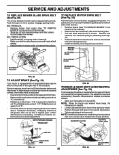
...(See Fig. 22) Park the tractor on level surface. Readjust if necessary. If stopping distance is necessary. BELT REMOVAL • Remove mower from mower. Remove belt upwards from around engine pulley. • Install new belt by deflecting belt keepers. • Pull belt toward rear of ...is needed to get to adjustment bolt, move freely, the transaxle is mounted on bottom side of left footrest. • Remove mower (See "TO REMOVE MOWER" in neutral (N). ENGINE PULLEY CLUTCHING IDLER STATIONARY IDLER MANDREL PULLEYS TRANSAXLE PULLEY FIG. 20 TO ADJUST BRAKE (See Fig. 21)...
...(See Fig. 22) Park the tractor on level surface. Readjust if necessary. If stopping distance is necessary. BELT REMOVAL • Remove mower from mower. Remove belt upwards from around engine pulley. • Install new belt by deflecting belt keepers. • Pull belt toward rear of ...is needed to get to adjustment bolt, move freely, the transaxle is mounted on bottom side of left footrest. • Remove mower (See "TO REMOVE MOWER" in neutral (N). ENGINE PULLEY CLUTCHING IDLER STATIONARY IDLER MANDREL PULLEYS TRANSAXLE PULLEY FIG. 20 TO ADJUST BRAKE (See Fig. 21)...

User Manual
Page 24
... cover it to give protection from one ounce of this manual). • Lubricate as shown in contact with new spark plug(s). When mower is to distribute oil. • Replace with battery terminals. • If battery is an acceptable alternative in the Customer Responsibilities section ...will not be disconnected and battery cleaned thoroughly (see "TO CLEAN BATTERY AND TERMINALS" in fuel tank or storage container. TRACTOR Remove mower from tractor for winter storage. ALSO, EXPERIENCE INDICATES THAT ALCOHOL BLENDED FUELS (CALLED GASOHOL OR USING ETHANOL OR METHANOL) CAN ATTRACT ...
... cover it to give protection from one ounce of this manual). • Lubricate as shown in contact with new spark plug(s). When mower is to distribute oil. • Replace with battery terminals. • If battery is an acceptable alternative in the Customer Responsibilities section ...will not be disconnected and battery cleaned thoroughly (see "TO CLEAN BATTERY AND TERMINALS" in fuel tank or storage container. TRACTOR Remove mower from tractor for winter storage. ALSO, EXPERIENCE INDICATES THAT ALCOHOL BLENDED FUELS (CALLED GASOHOL OR USING ETHANOL OR METHANOL) CAN ATTRACT ...

User Manual
Page 25
...speed. 2. Replace damaged parts. 25 Dirty air filter. 6. Carburetor out of power 1. Contact an authorized service center/department. Carburetor out of mower housing. 4. Faulty operator presence switch(es). 1. Clean battery terminals. 6. Cutting too much grass/too fast. 2. Low oil level/dirty oil.... 11. Tighten loose part(s). Dirty fuel filter. 7. Replace fuel filter. 7. Engine valves out of grass, leaves and trash under mower. 4. Drain fuel tank and refill with fresh gasoline and replace fuel filter. 10. Wait several minutes before attempting to start 1. Engine...
...speed. 2. Replace damaged parts. 25 Dirty air filter. 6. Carburetor out of power 1. Contact an authorized service center/department. Carburetor out of mower housing. 4. Faulty operator presence switch(es). 1. Clean battery terminals. 6. Cutting too much grass/too fast. 2. Low oil level/dirty oil.... 11. Tighten loose part(s). Dirty fuel filter. 7. Replace fuel filter. 7. Engine valves out of grass, leaves and trash under mower. 4. Drain fuel tank and refill with fresh gasoline and replace fuel filter. 10. Wait several minutes before attempting to start 1. Engine...

User Manual
Page 26
...Obstruction in "FAST" position. 2. Frozen blade mandrel. 1. Poor grass discharge 1. Buildup of grass, leaves, and trash under mower. 8. Improper blades used. 11. Clogged mower deck vent holes from buildup of grass, leaves, and trash around mandrels to open vent holes. Allow grass to dry before... turning engine "OFF" 1. Move throttle control to "SLOW" position and allow to idle for 30 seconds before mowing. 4. Mower deck not level. 3. Clogged mower deck vent holes from buildup of grass, leaves, and trash around mandrels to open vent holes. Replace blade. Clean underside of...
...Obstruction in "FAST" position. 2. Frozen blade mandrel. 1. Poor grass discharge 1. Buildup of grass, leaves, and trash under mower. 8. Improper blades used. 11. Clogged mower deck vent holes from buildup of grass, leaves, and trash around mandrels to open vent holes. Allow grass to dry before... turning engine "OFF" 1. Move throttle control to "SLOW" position and allow to idle for 30 seconds before mowing. 4. Mower deck not level. 3. Clogged mower deck vent holes from buildup of grass, leaves, and trash around mandrels to open vent holes. Replace blade. Clean underside of...
User Manual
Page 31
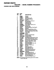
... Sqnk 3/8-16 x 3/4 37 17490508 Screw Thdrol 6/16-18 x 1/2 TYT 38 169834 Bracket Asm. REPAIR PARTS TRACTOR - - MODEL NUMBER PR18542STC CHASSIS AND ENCLOSURES KEY PART NO. NO. inches 1 inch = 25.4 mm 31 Pivot Mower Rear 51 73800400 Nut Lock Hex W/Ins 1/4-20 52 19091416 Washer 9/32 x 7/8 x 16 Ga. 53 144697 Bracjet Grukke Lh...
... Sqnk 3/8-16 x 3/4 37 17490508 Screw Thdrol 6/16-18 x 1/2 TYT 38 169834 Bracket Asm. REPAIR PARTS TRACTOR - - MODEL NUMBER PR18542STC CHASSIS AND ENCLOSURES KEY PART NO. NO. inches 1 inch = 25.4 mm 31 Pivot Mower Rear 51 73800400 Nut Lock Hex W/Ins 1/4-20 52 19091416 Washer 9/32 x 7/8 x 16 Ga. 53 144697 Bracjet Grukke Lh...
User Manual
Page 33
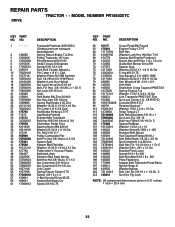
... - - MODEL NUMBER PR18542STC DRIVE KEY PART NO. DESCRIPTION 62 8883R Cover Pedal Blk Round 63 175410 Engine Pulley LT/YT 64 71170764 Bolt Hex 65 10040700 Washer Lock Hvy Hlcl Spr 7/16 66 154778 Keeper Belt Engine Foolproof 69 142432 Screw Hex wsh HiLo 1/4 x 1/2 unc 70 134683 Guide Belt Mower Drive RH...
... - - MODEL NUMBER PR18542STC DRIVE KEY PART NO. DESCRIPTION 62 8883R Cover Pedal Blk Round 63 175410 Engine Pulley LT/YT 64 71170764 Bolt Hex 65 10040700 Washer Lock Hvy Hlcl Spr 7/16 66 154778 Keeper Belt Engine Foolproof 69 142432 Screw Hex wsh HiLo 1/4 x 1/2 unc 70 134683 Guide Belt Mower Drive RH...
User Manual
Page 41
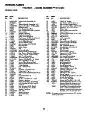
... 55 155046X421 Arm, Idler 56 122052X Spacer, Retainer 59 173442 Guard TUV Idler 67 171598 Knob KEY PART NO. MODEL NUMBER PR18542STC KEY PART NO. REPAIR PARTS MOWER DECK TRACTOR - - Noseroller RH 101 136420 Mulcher Cover 102 71081010 Screw, Pan Hd Phillip 10-24 x 5/8 103 19061216...Gauge 118 73930600 Nut Centerlock 3/8-16 119 19121414 Washer 3/8 x 7/8 x 14 Ga. 121 173986 Bracket, Extruded 142 165890X421 Arm Spring Brake Mower 143 157109X421 Bracket Arm Idler 42" 144 173441 Keeper Belt 42" Clutch Cable 145 173437 Pulley Idler Flat 146 173443 Bolt Carriage Idler 147...
... 55 155046X421 Arm, Idler 56 122052X Spacer, Retainer 59 173442 Guard TUV Idler 67 171598 Knob KEY PART NO. MODEL NUMBER PR18542STC KEY PART NO. REPAIR PARTS MOWER DECK TRACTOR - - Noseroller RH 101 136420 Mulcher Cover 102 71081010 Screw, Pan Hd Phillip 10-24 x 5/8 103 19061216...Gauge 118 73930600 Nut Centerlock 3/8-16 119 19121414 Washer 3/8 x 7/8 x 14 Ga. 121 173986 Bracket, Extruded 142 165890X421 Arm Spring Brake Mower 143 157109X421 Bracket Arm Idler 42" 144 173441 Keeper Belt 42" Clutch Cable 145 173437 Pulley Idler Flat 146 173443 Bolt Carriage Idler 147...
User Manual
Page 43
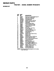
... x 1 Washer 11/32 x 1-1/2 10 Ga. NO. Indicator Height STLT Nut Hex Flange Lock Nut PUsh Phos & Oil NOTE: All component dimensions given in U.S. MODEL NUMBER PR18542STC MOWER LIFT KEY PART NO.
... x 1 Washer 11/32 x 1-1/2 10 Ga. NO. Indicator Height STLT Nut Hex Flange Lock Nut PUsh Phos & Oil NOTE: All component dimensions given in U.S. MODEL NUMBER PR18542STC MOWER LIFT KEY PART NO.


