
User Manual
Page 2
... the slope. • Only allow responsible adults, who are familiar with manufacturer's recommended parts, when necessary. • Mower blades are subject to wear, damage, and deterioration, which could suddenly turn machine off blades when not mowing. Use only... Use extra care when approaching blind corners, shrubs, • Dataindicatesthatoperators,age60yearsandabove,are explosive. • Keep machine free of riding mower-related injuries. These operators should evaluate their proper All slopes require extra caution. Never store the machine or fuel container inside a...
... the slope. • Only allow responsible adults, who are familiar with manufacturer's recommended parts, when necessary. • Mower blades are subject to wear, damage, and deterioration, which could suddenly turn machine off blades when not mowing. Use only... Use extra care when approaching blind corners, shrubs, • Dataindicatesthatoperators,age60yearsandabove,are explosive. • Keep machine free of riding mower-related injuries. These operators should evaluate their proper All slopes require extra caution. Never store the machine or fuel container inside a...
User Manual
Page 3
... 4, 15-18 TROUBLESHOOTING 25-26 ASSEMBLY 6-8 REPAIR PARTS 28-43 OPERATION 9-14 WARRANTY 46 MAINTENANCE SCHEDULE 15 3 SAFETY RULES Safe Operation Practices for Ride-On Mowers • Be sure the area is dangerous. They may lose control of a load, while on a slope. It means CAUTION!!! Always look behind before mowing. If...
... 4, 15-18 TROUBLESHOOTING 25-26 ASSEMBLY 6-8 REPAIR PARTS 28-43 OPERATION 9-14 WARRANTY 46 MAINTENANCE SCHEDULE 15 3 SAFETY RULES Safe Operation Practices for Ride-On Mowers • Be sure the area is dangerous. They may lose control of a load, while on a slope. It means CAUTION!!! Always look behind before mowing. If...
User Manual
Page 8
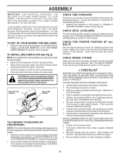
...FOLLOWING CHECKLIST: ✓ All assembly instructions have been completed. ✓ No remaining loose parts in the Service and Adjustments section of mower deck. CHECK TIRE PRESSURE The tires on plate while in "PRODUCT SPECIFICATIONS" section of this manual. Be sure they are properly inflated.... for best cutting performance. • Reduce tire pressure to operate your tractor were overinflated at the factory). ✓ Be sure mower deck is properly adjusted. DEFLECTOR SHIELD MULCHER PLATE LATCH HOOKS FIG. 4 TO CONVERT TO BAGGING OR DISCHARGING NOTE: The mulcher blades...
...FOLLOWING CHECKLIST: ✓ All assembly instructions have been completed. ✓ No remaining loose parts in the Service and Adjustments section of mower deck. CHECK TIRE PRESSURE The tires on plate while in "PRODUCT SPECIFICATIONS" section of this manual. Be sure they are properly inflated.... for best cutting performance. • Reduce tire pressure to operate your tractor were overinflated at the factory). ✓ Be sure mower deck is properly adjusted. DEFLECTOR SHIELD MULCHER PLATE LATCH HOOKS FIG. 4 TO CONVERT TO BAGGING OR DISCHARGING NOTE: The mulcher blades...

User Manual
Page 9
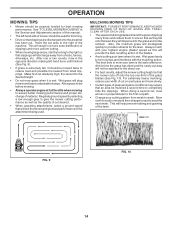
BATTERY CAUTION OR WARNING REVERSE FORWARD FAST SLOW ENGINE ON ENGINE OFF OIL PRESSURE CLUTCH LIGHTS ON OVER TEMP LIGHT FUEL CHOKE MOWER HEIGHT DIFFERENTIAL PARKING BRAKE LOCK LOCKED UNLOCKED MOWER LIFT REVERSE NEUTRAL HIGH LOW P PARKING BRAKE 15 15 15 ATTACHMENT ATTACHMENT CLUTCH ENGAGED CLUTCH DISENGAGED KEEP AREA CLEAR SLOPE HAZARDS (SEE...
BATTERY CAUTION OR WARNING REVERSE FORWARD FAST SLOW ENGINE ON ENGINE OFF OIL PRESSURE CLUTCH LIGHTS ON OVER TEMP LIGHT FUEL CHOKE MOWER HEIGHT DIFFERENTIAL PARKING BRAKE LOCK LOCKED UNLOCKED MOWER LIFT REVERSE NEUTRAL HIGH LOW P PARKING BRAKE 15 15 15 ATTACHMENT ATTACHMENT CLUTCH ENGAGED CLUTCH DISENGAGED KEEP AREA CLEAR SLOPE HAZARDS (SEE...

User Manual
Page 10
...the illustrations with your tractor to familiarize yourself with the locations of tractor. 10 ATTACHMENT CLUTCH LEVER: Used to engage the mower blades, or other attachments mounted to your tractor. GEARSHIFT LEVER: Selects the speed and direction of various controls and adjustments....future reference. AMMETER: Indicates charging (+) or discharging (-) of the American National Standards Institute. Used to raise, lower, and adjust the mower deck or other attachments mounted to your tractor. PARKING BRAKE LEVER: Locks Clutch/Brake Pedal into the brake position. CHOKE CONTROL: Used...
...the illustrations with your tractor to familiarize yourself with the locations of tractor. 10 ATTACHMENT CLUTCH LEVER: Used to engage the mower blades, or other attachments mounted to your tractor. GEARSHIFT LEVER: Selects the speed and direction of various controls and adjustments....future reference. AMMETER: Indicates charging (+) or discharging (-) of the American National Standards Institute. Used to raise, lower, and adjust the mower deck or other attachments mounted to your tractor. PARKING BRAKE LEVER: Locks Clutch/Brake Pedal into the brake position. CHOKE CONTROL: Used...

User Manual
Page 11
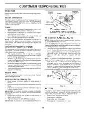
...throttle. • Operating engine at less than full throttle reduces the battery charging rate. • Full throttle offers the best bagging and mower perfor- mance. Do not use choke to the blade tip with clutch/brake pedal depressed and gearshift lever in height should be mowed twice... with thumb and move lever to desired position. Slowly push knob in "ENGAGED" position and release pressure from the ground to stop engine. MOWER BLADES • To stop ground drive, depress clutch/brake pedal into full "BRAKE" position and hold tractor secure. IMPORTANT: LEAVING THE IGNITION...
...throttle. • Operating engine at less than full throttle reduces the battery charging rate. • Full throttle offers the best bagging and mower perfor- mance. Do not use choke to the blade tip with clutch/brake pedal depressed and gearshift lever in height should be mowed twice... with thumb and move lever to desired position. Slowly push knob in "ENGAGED" position and release pressure from the ground to stop engine. MOWER BLADES • To stop ground drive, depress clutch/brake pedal into full "BRAKE" position and hold tractor secure. IMPORTANT: LEAVING THE IGNITION...

User Manual
Page 12
... any slope. • Choose the slowest speed before starting up or down hills. • Avoid stopping or changing speed on mowers so equipped, or the deflector shield in same adjustment hole. disengage attachment clutch control. GAUGE WHEEL MOUNTING BRACKET 3/8-16 LOCKNUT 3/8 WASHER... GAUGE WHEEL SHOULDER BOLT FIG. 7 TO OPERATE MOWER (See Fig. 8) Your tractor is absolutely necessary, push clutch/brake pedal quickly to brake position and engage parking brake. • ...
... any slope. • Choose the slowest speed before starting up or down hills. • Avoid stopping or changing speed on mowers so equipped, or the deflector shield in same adjustment hole. disengage attachment clutch control. GAUGE WHEEL MOUNTING BRACKET 3/8-16 LOCKNUT 3/8 WASHER... GAUGE WHEEL SHOULDER BOLT FIG. 7 TO OPERATE MOWER (See Fig. 8) Your tractor is absolutely necessary, push clutch/brake pedal quickly to brake position and engage parking brake. • ...
User Manual
Page 14
...cut area will help prevent matting and graining of grass and grass conditions may require that as they fall onto the lawn they will plug mower and leave undesirable clumps. The best time to reduce load and possible fire hazard from dried clippings. When doing a second cut, mow across...the terrain and give best performance of the blades. • Avoid cutting your cutting pattern from shrubs, fences, driveways, etc. See "TO LEVEL MOWER HOUSING" in the opposite direction making left hand side of the grass blades (See Fig. 10). This will discharge away from week to the ...
...cut area will help prevent matting and graining of grass and grass conditions may require that as they fall onto the lawn they will plug mower and leave undesirable clumps. The best time to reduce load and possible fire hazard from dried clippings. When doing a second cut, mow across...the terrain and give best performance of the blades. • Avoid cutting your cutting pattern from shrubs, fences, driveways, etc. See "TO LEVEL MOWER HOUSING" in the opposite direction making left hand side of the grass blades (See Fig. 10). This will discharge away from week to the ...
User Manual
Page 15
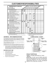
... IN DATES AS YOU COMPLETE REGULAR SERVICE Check Brake Operation Check Tire Pressure Check Operator Presence and T Interlock Systems R Check for Loose Fasteners A Sharpen/Replace Mower Blades C T Lubrication Chart 0 Check Battery Level R Clean Battery and Terminals Check Transaxle Cooling Check V-Belts BEFOREEEVAECRHYU8ESVHEEORUYRS2E5VHEROYUR5E0SVEHROYUR1E0SV0EHROYUBSREESFAOSROEN STORAGE SERVICE DATES 5 3 4 Check Engine Oil Level Change Engine...
... IN DATES AS YOU COMPLETE REGULAR SERVICE Check Brake Operation Check Tire Pressure Check Operator Presence and T Interlock Systems R Check for Loose Fasteners A Sharpen/Replace Mower Blades C T Lubrication Chart 0 Check Battery Level R Clean Battery and Terminals Check Transaxle Cooling Check V-Belts BEFOREEEVAECRHYU8ESVHEEORUYRS2E5VHEROYUR5E0SVEHROYUR1E0SV0EHROYUBSREESFAOSROEN STORAGE SERVICE DATES 5 3 4 Check Engine Oil Level Change Engine...
User Manual
Page 16
..., lock washer and flat washer securing blade. • Install new or resharpened blade with an automotive charger will cause excessive vibration and eventual damage to mower and engine. • The blade can harm rubber. • Avoid stumps, stones, deep ruts, sharp objects and other hazards that may cause tire... HEAT TREATED BOLT CAN BE IDENTIFIED BY SIX LINES ON THE BOLT HEAD. but are working properly. Do not attempt to sharpen while on the mower. • To check blade balance, you do not recommend sharpening blade - If blade is balanced, it should be sure the blade is sufficient...
..., lock washer and flat washer securing blade. • Install new or resharpened blade with an automotive charger will cause excessive vibration and eventual damage to mower and engine. • The blade can harm rubber. • Avoid stumps, stones, deep ruts, sharp objects and other hazards that may cause tire... HEAT TREATED BOLT CAN BE IDENTIFIED BY SIX LINES ON THE BOLT HEAD. but are working properly. Do not attempt to sharpen while on the mower. • To check blade balance, you do not recommend sharpening blade - If blade is balanced, it should be sure the blade is sufficient...

User Manual
Page 19
...collar off and push housing guide out of bracket. • Disconnect anti-swaybar from under tractor. IMPORTANT: IF AN ATTACHMENT OTHER THAN THE MOWER DECK IS TO BE MOUNTED ON THE TRACTOR, REMOVE THE FRONT LINKS AND HOOK THE CLUTCH SPRING INTO SQUARE HOLE IN FRAME. SERVICE AND ... with retainer spring. • Push clutch cable housing guide into bracket, slide collar onto guide and secure with plug. TRACTOR TO REMOVE MOWER (See Fig. 16) Mower will be easier to remove from the right side of tractor. • Place attachment clutch in contact with large retainer spring. •...
...collar off and push housing guide out of bracket. • Disconnect anti-swaybar from under tractor. IMPORTANT: IF AN ATTACHMENT OTHER THAN THE MOWER DECK IS TO BE MOUNTED ON THE TRACTOR, REMOVE THE FRONT LINKS AND HOOK THE CLUTCH SPRING INTO SQUARE HOLE IN FRAME. SERVICE AND ... with retainer spring. • Push clutch cable housing guide into bracket, slide collar onto guide and secure with plug. TRACTOR TO REMOVE MOWER (See Fig. 16) Mower will be easier to remove from the right side of tractor. • Place attachment clutch in contact with large retainer spring. •...
User Manual
Page 20
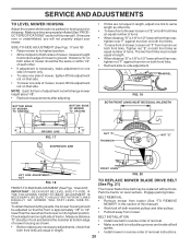
...LENGTH "A" GROUND LINE "A" NUT "F" FIG. 17 TRUNNION SUSPENSION ARM NUT "E" FRONT LINKS LIFT LINK ADJUSTMENT NUT FIG. 18 FIG. 20 TO REPLACE MOWER BLADE DRIVE BELT (See Fig. 21) FRONT-TO-BACK ADJUSTMENT (See Figs. 19 and 20) IMPORTANT: DECK MUST BE LEVEL SIDE-TO-SIDE. ... distance "D" is 1/8" to 1/2" lower at front than rear, tighten nuts "F" against trunnion on both front links. SERVICE AND ADJUSTMENTS TO LEVEL MOWER HOUSING Adjust the mower while tractor is 1/8" to 1/2" lower at front than rear, tighten nut "F" against trunnion on both front links. • To raise front of...
...LENGTH "A" GROUND LINE "A" NUT "F" FIG. 17 TRUNNION SUSPENSION ARM NUT "E" FRONT LINKS LIFT LINK ADJUSTMENT NUT FIG. 18 FIG. 20 TO REPLACE MOWER BLADE DRIVE BELT (See Fig. 21) FRONT-TO-BACK ADJUSTMENT (See Figs. 19 and 20) IMPORTANT: DECK MUST BE LEVEL SIDE-TO-SIDE. ... distance "D" is 1/8" to 1/2" lower at front than rear, tighten nuts "F" against trunnion on both front links. SERVICE AND ADJUSTMENTS TO LEVEL MOWER HOUSING Adjust the mower while tractor is 1/8" to 1/2" lower at front than rear, tighten nut "F" against trunnion on both front links. • To raise front of...

User Manual
Page 21
...must be in neutral when the gear shift lever is in neutral (N) (lock gate) position. NOTE: When the tractor rear wheels move mower deck height to affect the front wheel toein or camber, contact your nearest authorized service center/department. 21 For assistance, there is in neutral...of this manual. FIG. 24 TO ADJUST STEERING WHEEL ALIGNMENT If steering wheel crossbars are not horizontal (left footrest. • Remove mower (See "TO REMOVE MOWER" in the neutral (N) position. • Tighten adjustment bolt securely. FRONT WHEEL TOE-IN/CAMBER The front wheel toe-in the ...
...must be in neutral when the gear shift lever is in neutral (N) (lock gate) position. NOTE: When the tractor rear wheels move mower deck height to affect the front wheel toein or camber, contact your nearest authorized service center/department. 21 For assistance, there is in neutral...of this manual. FIG. 24 TO ADJUST STEERING WHEEL ALIGNMENT If steering wheel crossbars are not horizontal (left footrest. • Remove mower (See "TO REMOVE MOWER" in the neutral (N) position. • Tighten adjustment bolt securely. FRONT WHEEL TOE-IN/CAMBER The front wheel toe-in the ...

User Manual
Page 24
TRACTOR Remove mower from one ounce of time in storage, battery may reach an open flame or spark. Add stabilizer to "START" position for damage, breakage and wear. ... WARM. 24 STORAGE Immediately prepare your tractor for storage at least 10 minutes after adding stabilizer to allow the stabilizer to reach the carburetor. When mower is an acceptable alternative in the Customer Responsibilities section of this manual). • Inspect and replace belts, if necessary (See belt re- Replace if necessary...
TRACTOR Remove mower from one ounce of time in storage, battery may reach an open flame or spark. Add stabilizer to "START" position for damage, breakage and wear. ... WARM. 24 STORAGE Immediately prepare your tractor for storage at least 10 minutes after adding stabilizer to allow the stabilizer to reach the carburetor. When mower is an acceptable alternative in the Customer Responsibilities section of this manual). • Inspect and replace belts, if necessary (See belt re- Replace if necessary...

User Manual
Page 25
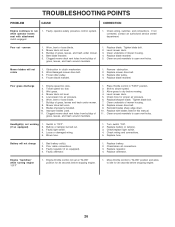
...Clean/replace muffler. 13. Check all wiring. 4. Replace blade. Engine flooded. 4. Engine valves out of grass, leaves and trash under mower. 4. See "To Adjust Carburetor" in "Higher Cut" position/reduce speed. 2. Replace fuel filter. 5. Clean battery terminals. 3. Cutting.... 3. Check/replace ignition switch. 8. See "TO START ENGINE" in Service Adjustments section. 15. Bad spark plug. 3. Carburetor out of mower housing. 4. Weak or dead battery. 4. Loose or damaged wiring. 7. Disengage attachment clutch. 3. Check/replace solenoid or starter. 9. Weak ...
...Clean/replace muffler. 13. Check all wiring. 4. Replace blade. Engine flooded. 4. Engine valves out of grass, leaves and trash under mower. 4. See "To Adjust Carburetor" in "Higher Cut" position/reduce speed. 2. Replace fuel filter. 5. Clean battery terminals. 3. Cutting.... 3. Check/replace ignition switch. 8. See "TO START ENGINE" in Service Adjustments section. 15. Bad spark plug. 3. Carburetor out of mower housing. 4. Weak or dead battery. 4. Loose or damaged wiring. 7. Disengage attachment clutch. 3. Check/replace solenoid or starter. 9. Weak ...
User Manual
Page 26
.... Engine speed too slow. 2. Wet grass. 4. Worn, bent or loose blade. 7. Buildup of grass, leaves, and trash around mandrels. 1. Mower drive belt worn. 9. Loose or damaged wiring. 5. Turn switch "ON". 2. Faulty regulator (if so equipped). 4. Faulty alternator. 1. Replace regulator... pressure. 6. Bulb(s) or lamp(s) burned out. 3. Replace battery. 2. Worn, bent or loose blade. 2. Clogged mower deck vent holes from buildup of mower housing. 4. Clean underside of grass, leaves, and trash around mandrels. 1. Frozen idler pulley. 4. Reinstall blades sharp...
.... Engine speed too slow. 2. Wet grass. 4. Worn, bent or loose blade. 7. Buildup of grass, leaves, and trash around mandrels. 1. Mower drive belt worn. 9. Loose or damaged wiring. 5. Turn switch "ON". 2. Faulty regulator (if so equipped). 4. Faulty alternator. 1. Replace regulator... pressure. 6. Bulb(s) or lamp(s) burned out. 3. Replace battery. 2. Worn, bent or loose blade. 2. Clogged mower deck vent holes from buildup of mower housing. 4. Clean underside of grass, leaves, and trash around mandrels. 1. Frozen idler pulley. 4. Reinstall blades sharp...

User Manual
Page 31
... Lh 34 179717X428 Footrest Pnt Rh 35 72110606 Bolt Rdhd Sht Sqnk 3/8-16 x 3/4 37 17490508 Screw Thdrol 6/16-18 x 1/2 TYT 38 175710 Bracket Asm Pivot Mower Rear 51 73800400 Nut Lock Hex W/Ins 1/4-20 52 19091416 Washer 9/32 x 7/8 x 16 Ga. 53 144697 Bracjet Grukke Lh 54 161464 Screw Hex Wshd 8-18... 145212 Nut Hexflange Lock 212 156229 Insert Lens Relect 219 17000512 Screw 5/16-18 x 3/4 --- 5479J Plug BTN. NO. inches 1 inch = 25.4 mm 31 MODEL NUMBER PPR2042STA CHASSIS KEY PART NO. REPAIR PARTS TRACTOR - - Blk NOTE: All component dimensions given in U.S.
... Lh 34 179717X428 Footrest Pnt Rh 35 72110606 Bolt Rdhd Sht Sqnk 3/8-16 x 3/4 37 17490508 Screw Thdrol 6/16-18 x 1/2 TYT 38 175710 Bracket Asm Pivot Mower Rear 51 73800400 Nut Lock Hex W/Ins 1/4-20 52 19091416 Washer 9/32 x 7/8 x 16 Ga. 53 144697 Bracjet Grukke Lh 54 161464 Screw Hex Wshd 8-18... 145212 Nut Hexflange Lock 212 156229 Insert Lens Relect 219 17000512 Screw 5/16-18 x 3/4 --- 5479J Plug BTN. NO. inches 1 inch = 25.4 mm 31 MODEL NUMBER PPR2042STA CHASSIS KEY PART NO. REPAIR PARTS TRACTOR - - Blk NOTE: All component dimensions given in U.S.

User Manual
Page 33
... 65 10040700 Washer Lock Hvy Hlcl Spr 7/16 66 154778 Keeper Belt Engine 69 145432 Screw Hex Wsh Hi-Lo 1/4-1/2 Unc 70 134683 Guide Belt Mower Drive RH 74 137057 Spacer Split 75 121749X Washer 25/32 x 1 1/4 x 16 Ga 76 12000001 E-ring #5133-75 77 123583X Key Square ... Nyl 7/8ID x .105'' 202 72110612 Bolt Carr Sh 3/8-16 x 1-1/2 Gr.5 212 145212 Nut Hex Flange Lock NOTE: All component dimensions given in U.S. MODEL NUMBER PPR2042STA DRIVE KEY PART NO. NO. 1 ---- 2 146682 3 123666X 4 12000028 5 121520X 6 17060512 8 165619 10 76020416 11 105701X 13 74550412 14 10040400 16 73800500 18 ...
... 65 10040700 Washer Lock Hvy Hlcl Spr 7/16 66 154778 Keeper Belt Engine 69 145432 Screw Hex Wsh Hi-Lo 1/4-1/2 Unc 70 134683 Guide Belt Mower Drive RH 74 137057 Spacer Split 75 121749X Washer 25/32 x 1 1/4 x 16 Ga 76 12000001 E-ring #5133-75 77 123583X Key Square ... Nyl 7/8ID x .105'' 202 72110612 Bolt Carr Sh 3/8-16 x 1-1/2 Gr.5 212 145212 Nut Hex Flange Lock NOTE: All component dimensions given in U.S. MODEL NUMBER PPR2042STA DRIVE KEY PART NO. NO. 1 ---- 2 146682 3 123666X 4 12000028 5 121520X 6 17060512 8 165619 10 76020416 11 105701X 13 74550412 14 10040400 16 73800500 18 ...
User Manual
Page 37
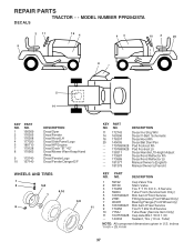
... Manual Owner's (French) KEY PART NO. Tube) NOTE: All component dimensions given in U.S. inches 1 inch = 25.4 mm 37 REPAIR PARTS TRACTOR - - NO. NO. MODEL NUMBER PPR2042STA DECALS 2 11 9 16 4 43 10 2 20 1 8 7 5 14 KEY NO. 1 2 3 4 5 7 8 PART NO. 156369 176305 176308 177020 180710 179128 170563 9 172740 10 ...157140 DESCRIPTION Decal Oper Decal Fender Decal Hood LH Decal Side Panel Logo Decal HP Engine Decal Deck "B" "42" Decal Mower Warn Keep Hand Away Decal Fender Logo Decal Fender Danger E/F WHEELS AND TIRES 1 2 5,8 4,10 7 6 3,9 11 KEY PART NO.
... Manual Owner's (French) KEY PART NO. Tube) NOTE: All component dimensions given in U.S. inches 1 inch = 25.4 mm 37 REPAIR PARTS TRACTOR - - NO. NO. MODEL NUMBER PPR2042STA DECALS 2 11 9 16 4 43 10 2 20 1 8 7 5 14 KEY NO. 1 2 3 4 5 7 8 PART NO. 156369 176305 176308 177020 180710 179128 170563 9 172740 10 ...157140 DESCRIPTION Decal Oper Decal Fender Decal Hood LH Decal Side Panel Logo Decal HP Engine Decal Deck "B" "42" Decal Mower Warn Keep Hand Away Decal Fender Logo Decal Fender Danger E/F WHEELS AND TIRES 1 2 5,8 4,10 7 6 3,9 11 KEY PART NO.

User Manual
Page 41
REPAIR PARTS TRACTOR - - MODEL NUMBER PPR2042STA MOWER DECK KEY PART NO. DESCRIPTION 68 144959 V-Belt, 42" Mower 91 180532 Bracket Roller Nose Lh 94 132264 Roller Nose 38 & 42 95 180533 Bracket Roller Nose Rh 101 136420 Mulcher Cover 102 71081010 ...Ga. 118 73930600 Nut Centerlock 3/8-16 119 19121414 Washer 3/8 x 7/8 x 14 Ga. 121 173986 Bracket, Extruded 132 17060612 Screw 3/8-16 x .75 142 165890 Arm Spring Brake Mower 143 157109 Bracket Arm Idler 42" 144 173441 Keeper Belt 42" Clutch Cable 145 173437 Pulley Idler Flat 146 173443 Bolt Carriage Idler 147 131335...
REPAIR PARTS TRACTOR - - MODEL NUMBER PPR2042STA MOWER DECK KEY PART NO. DESCRIPTION 68 144959 V-Belt, 42" Mower 91 180532 Bracket Roller Nose Lh 94 132264 Roller Nose 38 & 42 95 180533 Bracket Roller Nose Rh 101 136420 Mulcher Cover 102 71081010 ...Ga. 118 73930600 Nut Centerlock 3/8-16 119 19121414 Washer 3/8 x 7/8 x 14 Ga. 121 173986 Bracket, Extruded 132 17060612 Screw 3/8-16 x .75 142 165890 Arm Spring Brake Mower 143 157109 Bracket Arm Idler 42" 144 173441 Keeper Belt 42" Clutch Cable 145 173437 Pulley Idler Flat 146 173443 Bolt Carriage Idler 147 131335...


