
User Manual
Page 2
... unit and disengage the controls quickly. • Never allow bystanders near or under rotating parts. • Exercise extreme caution when operating on slippery surfaces. • Handle fuel with extreme care. It means CAUTION!!! Be thoroughly familiar with fuel in safe working condition. • Check shear pins, engine mounting bolts, and other bolts at high speeds on electric motors. • Do not run the engine indoors; The tines may...
... unit and disengage the controls quickly. • Never allow bystanders near or under rotating parts. • Exercise extreme caution when operating on slippery surfaces. • Handle fuel with extreme care. It means CAUTION!!! Be thoroughly familiar with fuel in safe working condition. • Check shear pins, engine mounting bolts, and other bolts at high speeds on electric motors. • Do not run the engine indoors; The tines may...
User Manual
Page 3
... assemble and maintain your authorized service center/ DEPARTMENT for and using your purchase of a new tiller. PRODUCT SPECIFICATIONS Gasolina Capacity: Oil (API-SG-SL): (Capacity: 20 oz./0.6L) Spark Plug : (Gap: .030"/0.76mm) 3 Quarts (2.8L) Unleaded Regular SAE 30 (Above 40°F/4°C) SAE 5W-30 (Below 40°F/4°C) Champion RC12YC CONGRATULATIONS on your tiller. • Follow instructions under "Maintenance" and "Storage" sections of this Owner's Manual...
... assemble and maintain your authorized service center/ DEPARTMENT for and using your purchase of a new tiller. PRODUCT SPECIFICATIONS Gasolina Capacity: Oil (API-SG-SL): (Capacity: 20 oz./0.6L) Spark Plug : (Gap: .030"/0.76mm) 3 Quarts (2.8L) Unleaded Regular SAE 30 (Above 40°F/4°C) SAE 5W-30 (Below 40°F/4°C) Champion RC12YC CONGRATULATIONS on your tiller. • Follow instructions under "Maintenance" and "Storage" sections of this Owner's Manual...

User Manual
Page 4
... shipping purposes. OPERATOR'S POSITION FIG. 1 CONTENTS OF HARDWARE PACK (2) Handle Lock (1) Carriage Bolt 3/8-16 UNC x 1 Gr. 5 (1) Center Locknut 3/8-16 UNC (1) Flat Washer 13/32 x 1 x 11 Ga. (1) Cable Clip (1) Handle Lock Lever (1) Hairpin Clip (1) Pivot Bolt 3/8-16 UNC Grade 5 4 (2) Shear Pins & Clips Standard wrench sizes are listed. (1) Utility knife (1) Tire pressure gauge (1) Pair of those parts left hand is mentioned in the operating position (standing behind tiller handles). Use the correct tools as necessary to...
... shipping purposes. OPERATOR'S POSITION FIG. 1 CONTENTS OF HARDWARE PACK (2) Handle Lock (1) Carriage Bolt 3/8-16 UNC x 1 Gr. 5 (1) Center Locknut 3/8-16 UNC (1) Flat Washer 13/32 x 1 x 11 Ga. (1) Cable Clip (1) Handle Lock Lever (1) Hairpin Clip (1) Pivot Bolt 3/8-16 UNC Grade 5 4 (2) Shear Pins & Clips Standard wrench sizes are listed. (1) Utility knife (1) Tire pressure gauge (1) Pair of those parts left hand is mentioned in the operating position (standing behind tiller handles). Use the correct tools as necessary to...

User Manual
Page 5
...; Raise handle assembly to highest position and securely tighten handle lock lever by rotating clockwise. Slide handle assembly into position.) VIEWED FROM R.H. IMPORTANT:WHEN UNPACKING AND ASSEMBLINGTILLER, BE CAREFUL NOT TO STRETCH OR KINK CABLES. • While holding handle assembly, cut cable ties securing handle assembly to connect shift rod. side of tiller and loosely assemble locknut (See Fig. 5). • Insert pivot bolt in highest position will allow for easier adjustment...
...; Raise handle assembly to highest position and securely tighten handle lock lever by rotating clockwise. Slide handle assembly into position.) VIEWED FROM R.H. IMPORTANT:WHEN UNPACKING AND ASSEMBLINGTILLER, BE CAREFUL NOT TO STRETCH OR KINK CABLES. • While holding handle assembly, cut cable ties securing handle assembly to connect shift rod. side of tiller and loosely assemble locknut (See Fig. 5). • Insert pivot bolt in highest position will allow for easier adjustment...

User Manual
Page 7
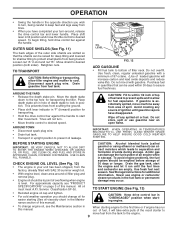
...being buried. DRIVE CONTROL BAR THROTTLE CONTROL SHIFT LEVER CHOKE CONTROL SHIFT LEVER INDICATOR DEPTH STAKE LEVELING SHIELD OUTER SIDE SHIELD RECOIL STARTER HANDLE FIG. 8 MEETS ANSI SAFETY REQUIREMENTS Our tillers conform to engage tines. Used when starting a cold engine. Used to the safety standards of various controls and adjustments. LEVELING SHIELD - Used to shift transmission gears. OPERATION KNOW YOUR TILLER READ THIS OWNER'S MANUAL AND SAFETY RULES BEFORE OPERATING YOUR TILLER. Save this manual for future reference. DRIVE CONTROL BAR - RECOIL STARTER HANDLE - Compare...
...being buried. DRIVE CONTROL BAR THROTTLE CONTROL SHIFT LEVER CHOKE CONTROL SHIFT LEVER INDICATOR DEPTH STAKE LEVELING SHIELD OUTER SIDE SHIELD RECOIL STARTER HANDLE FIG. 8 MEETS ANSI SAFETY REQUIREMENTS Our tillers conform to engage tines. Used when starting a cold engine. Used to the safety standards of various controls and adjustments. LEVELING SHIELD - Used to shift transmission gears. OPERATION KNOW YOUR TILLER READ THIS OWNER'S MANUAL AND SAFETY RULES BEFORE OPERATING YOUR TILLER. Save this manual for future reference. DRIVE CONTROL BAR - RECOIL STARTER HANDLE - Compare...
User Manual
Page 9
... and to allow tiller engine and muffler to cool. Do not mix oil with SAE 30 summer weight oil. • With engine level, clean area around , release the drive control bar and lower handle. CAUTION: Fill to within 30 days to assure fuel freshness. Wipe off any source of ignition until the fuel lines and carburetor are slotted so that can be used within 1/2 inch of top...
... and to allow tiller engine and muffler to cool. Do not mix oil with SAE 30 summer weight oil. • With engine level, clean area around , release the drive control bar and lower handle. CAUTION: Fill to within 30 days to assure fuel freshness. Wipe off any source of ignition until the fuel lines and carburetor are slotted so that can be used within 1/2 inch of top...
User Manual
Page 10
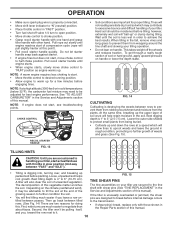
... tine assemblies on your tiller,start actual field use with other hand. Hard soil should be advisable to the transmission. • If shear pin(s) break, replace only with shear pins (See "TINE REPLACEMENT" in the soil. OPERATION • Make sure spark plug wire is properly connected. • Move shift lever indicator to "N" (neutral) position. • Place throttle control in "FAST" position. • Turn fuel shut-off the wheels and reduces traction. CHOKE CONTROL RUN CHOKE •...
... tine assemblies on your tiller,start actual field use with other hand. Hard soil should be advisable to the transmission. • If shear pin(s) break, replace only with shear pins (See "TINE REPLACEMENT" in the soil. OPERATION • Make sure spark plug wire is properly connected. • Move shift lever indicator to "N" (neutral) position. • Place throttle control in "FAST" position. • Turn fuel shut-off the wheels and reduces traction. CHOKE CONTROL RUN CHOKE •...
User Manual
Page 11
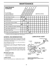
..."). A new spark plug and clean air filter assure proper air-fuel mixture and help your tiller. BEFORE EACH USE • Check engine oil level. • Check tine operation. • Check for wear. Service more often when operating under a heavy load or in this manual should replace the spark plug, clean or replace air filter, and check tines and belts for loose fasteners. Change more often when operating in the Service and Adjustments section of this manual. Some adjustments will need to be checked at...
..."). A new spark plug and clean air filter assure proper air-fuel mixture and help your tiller. BEFORE EACH USE • Check engine oil level. • Check tine operation. • Check for wear. Service more often when operating under a heavy load or in this manual should replace the spark plug, clean or replace air filter, and check tines and belts for loose fasteners. Change more often when operating in the Service and Adjustments section of this manual. Some adjustments will need to be checked at...
User Manual
Page 12
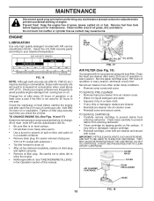
... check the oil level. See"CHECK ENGINE OIL LEVEL" in cold weather, these multi-viscosity oils will not run properly using a dirty air filter. MAINTENANCE Disconnect spark plug wire before oil change. Select the oil's SAE viscosity grade according to avoid possible engine damage from tank before starting the engine and after every 25 hours of all grass, dirt, and debris. Service air cleaner more frequently to your engine oil level more often under dusty conditions. • Remove cover screw...
... check the oil level. See"CHECK ENGINE OIL LEVEL" in cold weather, these multi-viscosity oils will not run properly using a dirty air filter. MAINTENANCE Disconnect spark plug wire before oil change. Select the oil's SAE viscosity grade according to avoid possible engine damage from tank before starting the engine and after every 25 hours of all grass, dirt, and debris. Service air cleaner more frequently to your engine oil level more often under dusty conditions. • Remove cover screw...

User Manual
Page 13
... surfaces and wheels free of this manual. Do not tamper with 1 oz. Replace if damaged. Spark plug type and gap setting is shown in engine will shorten the useful life of dirt and chaff. Water in "PRODUCT SPECIFICATIONS" on page 3 of all foreign mat- brush. • Remove blower housing and clean as necessary. • Keep cylinder fins free of your tiller when the engine and transmission are covered to clean your unit...
... surfaces and wheels free of this manual. Do not tamper with 1 oz. Replace if damaged. Spark plug type and gap setting is shown in engine will shorten the useful life of dirt and chaff. Water in "PRODUCT SPECIFICATIONS" on page 3 of all foreign mat- brush. • Remove blower housing and clean as necessary. • Keep cylinder fins free of your tiller when the engine and transmission are covered to clean your unit...
User Manual
Page 14
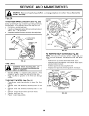
... tiller about 1 inch. • Remove two (2) screws from side of belt guard. • Remove hex nut and washer from bottom of belt guard (located behind wheel). • Pull belt guard out and away from unit. • Replace belt guard by removing nuts "C" and "D". • Remove hairpin clip and clevis pin from wheel. • Remove wheel and tire. • Repair tire and reassemble. BELT GUARD SCREW HEX NUT AND WASHER (LOCATED BEHIND TIRE) SCREW HAIRPIN CLIP AND CLEVIS PIN FIG. 22 14 CLEVIS PIN NUT "C" NUT "D" HANDLE (LOW POSITION) HANDLE (HIGH POSITION) HANDLE LOCK LEVER...
... tiller about 1 inch. • Remove two (2) screws from side of belt guard. • Remove hex nut and washer from bottom of belt guard (located behind wheel). • Pull belt guard out and away from unit. • Replace belt guard by removing nuts "C" and "D". • Remove hairpin clip and clevis pin from wheel. • Remove wheel and tire. • Repair tire and reassemble. BELT GUARD SCREW HEX NUT AND WASHER (LOCATED BEHIND TIRE) SCREW HAIRPIN CLIP AND CLEVIS PIN FIG. 22 14 CLEVIS PIN NUT "C" NUT "D" HANDLE (LOW POSITION) HANDLE (HIGH POSITION) HANDLE LOCK LEVER...

User Manual
Page 15
... screw securely. GROUND DRIVE BELT ADJUSTMENT (See Fig. 23) For proper belt tension, the extension spring should have about 5/8 inch (16 mm) stretch is obtained while the drive control bar is in groove of transmission pulley and into engine pulley. SERVICE AND ADJUSTMENTS TO REPLACE GROUND DRIVE BELT (See Figs. 22 and 23) • Remove belt guard as described in "TO REMOVE BELT GUARD". • Remove old belt by slipping off engine pulley first then remove from transmission pulley. • Place new belt...
... screw securely. GROUND DRIVE BELT ADJUSTMENT (See Fig. 23) For proper belt tension, the extension spring should have about 5/8 inch (16 mm) stretch is obtained while the drive control bar is in groove of transmission pulley and into engine pulley. SERVICE AND ADJUSTMENTS TO REPLACE GROUND DRIVE BELT (See Figs. 22 and 23) • Remove belt guard as described in "TO REMOVE BELT GUARD". • Remove old belt by slipping off engine pulley first then remove from transmission pulley. • Place new belt...
User Manual
Page 17
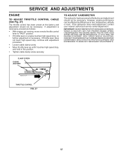
... throttle control lever to "FAST" position. • If throttle lever on engine touches high speed stop , and hold in fuel, temperature, altitude or load. If adjustment is necessary. OVERSPEEDING THE ENGINE ABOVE THE FACTORY HIGH SPEED SETTING CAN BE DANGEROUS. However, engine performance can be necessary. If the carburetor does need adjustment, contact your nearest authorized service center/department IMPORTANT: NEVERTAMPERWITHTHEENGINEGOVERNOR, WHICH IS FACTORY SET FOR PROPER ENGINE SPEED. CLAMP SCREW CASING AND WIRE engine_art_78 THROTTLE CONTROL...
... throttle control lever to "FAST" position. • If throttle lever on engine touches high speed stop , and hold in fuel, temperature, altitude or load. If adjustment is necessary. OVERSPEEDING THE ENGINE ABOVE THE FACTORY HIGH SPEED SETTING CAN BE DANGEROUS. However, engine performance can be necessary. If the carburetor does need adjustment, contact your nearest authorized service center/department IMPORTANT: NEVERTAMPERWITHTHEENGINEGOVERNOR, WHICH IS FACTORY SET FOR PROPER ENGINE SPEED. CLAMP SCREW CASING AND WIRE engine_art_78 THROTTLE CONTROL...
User Manual
Page 18
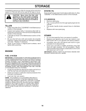
.... TILLER • Clean entire tiller (See "CLEANING" in the Maintenance section of this manual). • Inspect and replace belts, if necessary (See belt replacement instructions in the Service and Adjustments section of this manual). sand lightly before storing in fuel tank or storage container. Do not empty the gas tank and carburetor if using fuel stabilizer. CYLINDER(S) • Remove spark plug. • Pour 1 ounce (29 ml) of fuel gum deposits during storage. IMPORTANT: NEVER COVER TILLER WHILE ENGINE...
.... TILLER • Clean entire tiller (See "CLEANING" in the Maintenance section of this manual). • Inspect and replace belts, if necessary (See belt replacement instructions in the Service and Adjustments section of this manual). sand lightly before storing in fuel tank or storage container. Do not empty the gas tank and carburetor if using fuel stabilizer. CYLINDER(S) • Remove spark plug. • Pour 1 ounce (29 ml) of fuel gum deposits during storage. IMPORTANT: NEVER COVER TILLER WHILE ENGINE...
User Manual
Page 19
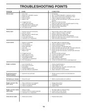
...1. Replace shear pin(s). 19 Clogged fuel tank. 7. Hard to start CAUSE 1. Replace spark plug or adjust gap. 4. Engine flooded. 4. Dirty air cleaner. 3. Loss of adjustment. 13. Dirty engine air screen. 3. Dirty engine. 4. Make necessary adjustments. 13. Check oil level/change spark plug. 5. Remove and clean muffler. 5. Set depth stake for more favorable soil conditions. 1. Loose spark plug wire. 8. Throttle control not set properly. 2. Oil in "FAST" position. 2. Ground too wet. Engine runs but tiller won't move 1. Fill fuel tank...
...1. Replace shear pin(s). 19 Clogged fuel tank. 7. Hard to start CAUSE 1. Replace spark plug or adjust gap. 4. Engine flooded. 4. Dirty air cleaner. 3. Loss of adjustment. 13. Dirty engine air screen. 3. Dirty engine. 4. Make necessary adjustments. 13. Check oil level/change spark plug. 5. Remove and clean muffler. 5. Set depth stake for more favorable soil conditions. 1. Loose spark plug wire. 8. Throttle control not set properly. 2. Oil in "FAST" position. 2. Ground too wet. Engine runs but tiller won't move 1. Fill fuel tank...

User Manual
Page 20
... 532 11 06-75 Cable, Clutch 27 873 90 04-00 Nut Hex Flange 1/4-20 unc 31 532 15 06-96 Bolt, Pivot NOTE: All component dimensions given in U.S. MODEL NUMBER PPCRT55 (96091001200), PRODUCT NUMBER 960 91 00-12 HANDLE ASSEMBLY 7 9 6 4 3 5 26 3 12 13 10 2 2 14 11 27 25 15 26 24 23 22 20 KEY PART NO. inches. 1 inch = 25.4 mm 20...
... 532 11 06-75 Cable, Clutch 27 873 90 04-00 Nut Hex Flange 1/4-20 unc 31 532 15 06-96 Bolt, Pivot NOTE: All component dimensions given in U.S. MODEL NUMBER PPCRT55 (96091001200), PRODUCT NUMBER 960 91 00-12 HANDLE ASSEMBLY 7 9 6 4 3 5 26 3 12 13 10 2 2 14 11 27 25 15 26 24 23 22 20 KEY PART NO. inches. 1 inch = 25.4 mm 20...

User Manual
Page 21
NO. MODEL NUMBER PPCRT55 (96091001200), PRODUCT NUMBER 960 91 00-12 MAINFRAME, LEFT SIDE 7 6 39 8 9 10 65 5 32 32 65 12 13 21 4 37 36 14 33 32 38 16 67 34 31 29 22 27 19 30 66 28 3 40 26 40 44 15 23 24 mainframe_left_17 25 KEY PART NO. DESCRIPTION 2 810 04 06...-00 Washer, Lock 3/8 3 873 22 06-00 Nut, Hex 3/8-16 4 532 17 01-27 Shield, Inner Belt Guard RT 5 532 16 43-29 Pin Spirol Flared 6 532 11 01-11 Lever, Shift 7 872 11 04-04 Bolt, Carriage 1/4-20 x 1/2 Gr. 5 8 532 00 87-00 Plate, Shift Indicator 9 532 08 67-77 Screw, Hex, Washer Head, Slotted #10-24...
NO. MODEL NUMBER PPCRT55 (96091001200), PRODUCT NUMBER 960 91 00-12 MAINFRAME, LEFT SIDE 7 6 39 8 9 10 65 5 32 32 65 12 13 21 4 37 36 14 33 32 38 16 67 34 31 29 22 27 19 30 66 28 3 40 26 40 44 15 23 24 mainframe_left_17 25 KEY PART NO. DESCRIPTION 2 810 04 06...-00 Washer, Lock 3/8 3 873 22 06-00 Nut, Hex 3/8-16 4 532 17 01-27 Shield, Inner Belt Guard RT 5 532 16 43-29 Pin Spirol Flared 6 532 11 01-11 Lever, Shift 7 872 11 04-04 Bolt, Carriage 1/4-20 x 1/2 Gr. 5 8 532 00 87-00 Plate, Shift Indicator 9 532 08 67-77 Screw, Hex, Washer Head, Slotted #10-24...

User Manual
Page 23
...40 Kit, Bearing 23 532 10 21-11 Shaft, Reverse Idler 58 532 17 95-20 Bolt Shoulder 24 810 04 07-00 Washer, Lock 7/16 60 532 18 32-26 Fitting Grease 25 873 61 07-00 Nut, Hex 7/16-20 - - 532 00 60-66 Grease, Plastilube #1 27 532 14 30-09 Bearing, Shaft, Ground Drive L.H....36 Seal Asm, Oil 16 532 15 44-66 Shaft, Shift 48 532 18 84-85 Gearcase, R.H. DESCRIPTION 1 532 18 85-54 Transmission Assembly (Includes 29 532 10 21-34 Chain #35-50 Pitch Key Nos. 2-53) 30 532 15 07-37 Ground Shaft Assembly 2 532 18 84-82 Gearcase, L.H. MODEL NUMBER PPCRT55 (96091001200), PRODUCT NUMBER 960 91 00-...
...40 Kit, Bearing 23 532 10 21-11 Shaft, Reverse Idler 58 532 17 95-20 Bolt Shoulder 24 810 04 07-00 Washer, Lock 7/16 60 532 18 32-26 Fitting Grease 25 873 61 07-00 Nut, Hex 7/16-20 - - 532 00 60-66 Grease, Plastilube #1 27 532 14 30-09 Bearing, Shaft, Ground Drive L.H....36 Seal Asm, Oil 16 532 15 44-66 Shaft, Shift 48 532 18 84-85 Gearcase, R.H. DESCRIPTION 1 532 18 85-54 Transmission Assembly (Includes 29 532 10 21-34 Chain #35-50 Pitch Key Nos. 2-53) 30 532 15 07-37 Ground Shaft Assembly 2 532 18 84-82 Gearcase, L.H. MODEL NUMBER PPCRT55 (96091001200), PRODUCT NUMBER 960 91 00-...
User Manual
Page 26
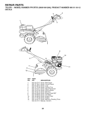
... PART NO. REPAIR PARTS TILLER - - DESCRIPTION 1 532 40 37-07 Decal, Belt Guard 2 532 15 78-01 Decal, Control Panel 3 532 40 36-53 Decal, Logo 4 532 13 75-38 Decal, Control Tine 5 532 12 04-31 Decal, Hand Placement 6 532 10 21-80 Decal, Shift Indicator 7 532 16 22-15 Decal, Warning 8 532 40 36-89 Decal, Engine... Intek REF 9 532 16 88-69 Decal, Tick Mark 10 532 19 48-08 Decal, Engine OHV 11 532 17 35-38 Decal, Engine 12 532 12 00-75 Decal, Warning, Rotating Tines - - 532 40 37-01 Manual, Owner's 26 NO.
... PART NO. REPAIR PARTS TILLER - - DESCRIPTION 1 532 40 37-07 Decal, Belt Guard 2 532 15 78-01 Decal, Control Panel 3 532 40 36-53 Decal, Logo 4 532 13 75-38 Decal, Control Tine 5 532 12 04-31 Decal, Hand Placement 6 532 10 21-80 Decal, Shift Indicator 7 532 16 22-15 Decal, Warning 8 532 40 36-89 Decal, Engine... Intek REF 9 532 16 88-69 Decal, Tick Mark 10 532 19 48-08 Decal, Engine OHV 11 532 17 35-38 Decal, Engine 12 532 12 00-75 Decal, Warning, Rotating Tines - - 532 40 37-01 Manual, Owner's 26 NO.
User Manual
Page 27
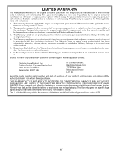
... improper assembly or installation, delivery damage, or to normal wear of the purchaser. Outdoor Products Customer Service Dept. 1030 Stevens Creek Road Augusta, GA 30907 USA In Canada contact: Electrolux Canada Corp. 7075 Ordan Drive Mississauga, Ontario L5T 1K6 giving the model number, serial number and ...any power equipment unit or attachment are belts, tines, tine adapters, normal wear, normal adjustments, standard hardware and normal maintenance. 6. This warranty does not apply to 90 days from the date of that this product as defined in replacing parts, any products used ...
... improper assembly or installation, delivery damage, or to normal wear of the purchaser. Outdoor Products Customer Service Dept. 1030 Stevens Creek Road Augusta, GA 30907 USA In Canada contact: Electrolux Canada Corp. 7075 Ordan Drive Mississauga, Ontario L5T 1K6 giving the model number, serial number and ...any power equipment unit or attachment are belts, tines, tine adapters, normal wear, normal adjustments, standard hardware and normal maintenance. 6. This warranty does not apply to 90 days from the date of that this product as defined in replacing parts, any products used ...


