Owner Manual
Page 1
ALWAYS WEAR EYE PROTECTION DURING OPERATION Visit our website: www.poulanpro.com Gasoline containing up to do so can result in serious injury. The use in U.S.A. IMPORTANT MANUAL Do Not Throw Away OPERATOR'S MANUAL MODEL: PPCRT14 REAR TINE TILLER WARNING: Read this machine. Failure to 10% ethanol (E10) is acceptable for use of any gasoline exceeding 10% ethanol (E10) will void the product warranty. 115 78 58-32 12.15.15 BY Printed in this Manual and follow all Warnings and Safety Instructions.
ALWAYS WEAR EYE PROTECTION DURING OPERATION Visit our website: www.poulanpro.com Gasoline containing up to do so can result in serious injury. The use in U.S.A. IMPORTANT MANUAL Do Not Throw Away OPERATOR'S MANUAL MODEL: PPCRT14 REAR TINE TILLER WARNING: Read this machine. Failure to 10% ethanol (E10) is acceptable for use of any gasoline exceeding 10% ethanol (E10) will void the product warranty. 115 78 58-32 12.15.15 BY Printed in this Manual and follow all Warnings and Safety Instructions.
Owner Manual
Page 2
... spark plug in hard ground. Stay alert for Walk-Behind Powered Rotary Tillers TRAINING • Read the Owner's Manual carefully. Never fill fuel tank indoors. • Replace gasoline cap securely and clean up , transporting, adjusting or making repairs. MAINTENANCE AND STORAGE • Keep machine, attachments, and accessories in safe working condition. • Never store the machine with electric drive motors or electric starting when setting up spilled fuel before restarting. • Use extension cords...
... spark plug in hard ground. Stay alert for Walk-Behind Powered Rotary Tillers TRAINING • Read the Owner's Manual carefully. Never fill fuel tank indoors. • Replace gasoline cap securely and clean up , transporting, adjusting or making repairs. MAINTENANCE AND STORAGE • Keep machine, attachments, and accessories in safe working condition. • Never store the machine with electric drive motors or electric starting when setting up spilled fuel before restarting. • Use extension cords...
Owner Manual
Page 3
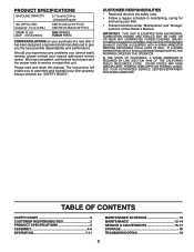
.... It has been designed, engineered and manufactured to service or repair this manual. IF A SPARK ARRESTER IS USED, IT SHOULD BE MAINTAINED IN EFFECTIVE WORKING ORDER BY THE OPERATOR. SEE YOUR AUTHORIZED SERVICE CENTER/DEPARTMENT FOR SPARK ARRESTER. TABLE OF CONTENTS SAFETY RULES 2 CUSTOMER RESPONSIBILITIES 3 PRODUCT SPECIFICATIONS 3 ASSEMBLY 4-6 OPERATION 7-11 MAINTENANCE SCHEDULE 12 MAINTENANCE 12-14 SERVICE & ADJUSTMENTS 15-17 STORAGE 18 TROUBLESHOOTING 19 3 We have competent...
.... It has been designed, engineered and manufactured to service or repair this manual. IF A SPARK ARRESTER IS USED, IT SHOULD BE MAINTAINED IN EFFECTIVE WORKING ORDER BY THE OPERATOR. SEE YOUR AUTHORIZED SERVICE CENTER/DEPARTMENT FOR SPARK ARRESTER. TABLE OF CONTENTS SAFETY RULES 2 CUSTOMER RESPONSIBILITIES 3 PRODUCT SPECIFICATIONS 3 ASSEMBLY 4-6 OPERATION 7-11 MAINTENANCE SCHEDULE 12 MAINTENANCE 12-14 SERVICE & ADJUSTMENTS 15-17 STORAGE 18 TROUBLESHOOTING 19 3 We have competent...
Owner Manual
Page 4
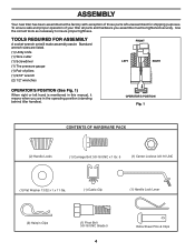
... HARDWARE PACK (2) Handle Locks (1) Carriage Bolt 3/8-16 UNC x 1 Gr. 5 (1) Center Locknut 3/8-16 UNC (1) Flat Washer 13/32 x 1 x 11 Ga. (1) Cable Clip (1) Handle Lock Lever (2) Hairpin Clips (1) Pivot Bolt 3/8-16 UNC Grade 5 4 Extra Shear Pins & Clips Use the correct tools as necessary to insure proper tightness. ASSEMBLY Your new tiller has been assembled at the factory with exception of those parts left hand is mentioned in the operating position (standing behind tiller handles).
... HARDWARE PACK (2) Handle Locks (1) Carriage Bolt 3/8-16 UNC x 1 Gr. 5 (1) Center Locknut 3/8-16 UNC (1) Flat Washer 13/32 x 1 x 11 Ga. (1) Cable Clip (1) Handle Lock Lever (2) Hairpin Clips (1) Pivot Bolt 3/8-16 UNC Grade 5 4 Extra Shear Pins & Clips Use the correct tools as necessary to insure proper tightness. ASSEMBLY Your new tiller has been assembled at the factory with exception of those parts left hand is mentioned in the operating position (standing behind tiller handles).

Owner Manual
Page 5
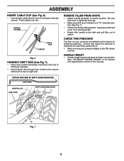
... AND ASSEMBLING TILLER, BE CAREFUL NOT TO STRETCH OR KINK CABLES. • While holding handle assembly, cut cable ties securing handle assembly to highest position and securely tighten handle lock lever by rotating clockwise. Tighten nut on top of carton. • Cut down right hand front and right hand rear corners of carton and lay panels flat. • Lower the handle assembly. Insert rear carriage carton_1 bolt first...
... AND ASSEMBLING TILLER, BE CAREFUL NOT TO STRETCH OR KINK CABLES. • While holding handle assembly, cut cable ties securing handle assembly to highest position and securely tighten handle lock lever by rotating clockwise. Tighten nut on top of carton. • Cut down right hand front and right hand rear corners of carton and lay panels flat. • Lower the handle assembly. Insert rear carriage carton_1 bolt first...
Owner Manual
Page 6
... of shift rod farthest from leveling shield. • Rotate tiller handle to secure with bend of this manual). CHECK TIRE PRESSURE The tires on the back of carton. HANDLE HEIGHT • Handle height may be adjusted to lowest position. ATTACH THIS END TO SHIFT LEVER INDICATOR SHIFT ROD HAIRPIN CLIP SHIFT ROD SHIFT LEVER INDICATOR Fig. 7 6 Separate cardboard cover from bend into hole of...
... of shift rod farthest from leveling shield. • Rotate tiller handle to secure with bend of this manual). CHECK TIRE PRESSURE The tires on the back of carton. HANDLE HEIGHT • Handle height may be adjusted to lowest position. ATTACH THIS END TO SHIFT LEVER INDICATOR SHIFT ROD HAIRPIN CLIP SHIFT ROD SHIFT LEVER INDICATOR Fig. 7 6 Separate cardboard cover from bend into hole of...

Owner Manual
Page 7
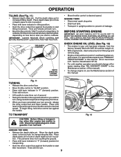
DRIVE CONTROL BAR SHIFT LEVER THROTTLE CONTROL SHIFT LEVER INDICATOR FUEL VALVE ENGINE ON/OFF SWITCH DEPTH STAKE LEVELING SHIELD RECOIL STARTER HANDLE Fig. 8 MEETS ANSI SAFETY REQUIREMENTS Our tillers conform to start the engine. LEVELING SHIELD - Controls engine speed. 7 FUEL VALVE - DEPTH STAKE - RECOIL STARTER HANDLE - SHIFT LEVER - SHIFT LEVER INDICATOR - The engine switch enables and disables the ignition system. The fuel valve opens and closes the passage between the fuel tank and the carburetor. Controls depth at which gear the transmission is in ...
DRIVE CONTROL BAR SHIFT LEVER THROTTLE CONTROL SHIFT LEVER INDICATOR FUEL VALVE ENGINE ON/OFF SWITCH DEPTH STAKE LEVELING SHIELD RECOIL STARTER HANDLE Fig. 8 MEETS ANSI SAFETY REQUIREMENTS Our tillers conform to start the engine. LEVELING SHIELD - Controls engine speed. 7 FUEL VALVE - DEPTH STAKE - RECOIL STARTER HANDLE - SHIFT LEVER - SHIFT LEVER INDICATOR - The engine switch enables and disables the ignition system. The fuel valve opens and closes the passage between the fuel tank and the carburetor. Controls depth at which gear the transmission is in ...

Owner Manual
Page 8
... POSITION FUEL VALVE ENGINE SWITCH Fig. 9 DEEPEST TILLING DEPTH STAKE 8 depth_stake_2 Fig. 10 HOW TO USE YOUR TILLER Know how to operate all controls before moving shift lever to ( ) till position and engaging drive control bar. TINE OPERATION - WHEELS ONLY/TINES STOPPED • DO NOT STAND DIRECTLY BEHIND TILLER. • Release the drive control bar. • Move throttle control to "SLOW" position. • Move shift lever indicator to "R" (reverse) position. • Hold drive control bar against the handle to start engine. OPERATION...
... POSITION FUEL VALVE ENGINE SWITCH Fig. 9 DEEPEST TILLING DEPTH STAKE 8 depth_stake_2 Fig. 10 HOW TO USE YOUR TILLER Know how to operate all controls before moving shift lever to ( ) till position and engaging drive control bar. TINE OPERATION - WHEELS ONLY/TINES STOPPED • DO NOT STAND DIRECTLY BEHIND TILLER. • Release the drive control bar. • Move throttle control to "SLOW" position. • Move shift lever indicator to "R" (reverse) position. • Hold drive control bar against the handle to start engine. OPERATION...
Owner Manual
Page 9
.... CHECK ENGINE OIL LEVEL (See Fig. 12) • The engine in tilling position. • Hold the drive control bar against the handle. OIL FILLER PLUG MAXIMUM UPPER LEVEL MINIMUM UPPER LEVEL Fig. 12 AROUND THE YARD • Release the depth stake pin. USE CLEAN FILL FUNNELS. For approximate capacity see the Maintenance section of overflowing when engine is level. "RELEASED" POSITION depth_stake_16 DEPTH STAKE PIN "LOCKED" POSITION TURNING Fig. 11 • Release the drive control bar. • Move throttle control to start tiller...
.... CHECK ENGINE OIL LEVEL (See Fig. 12) • The engine in tilling position. • Hold the drive control bar against the handle. OIL FILLER PLUG MAXIMUM UPPER LEVEL MINIMUM UPPER LEVEL Fig. 12 AROUND THE YARD • Release the depth stake pin. USE CLEAN FILL FUNNELS. For approximate capacity see the Maintenance section of overflowing when engine is level. "RELEASED" POSITION depth_stake_16 DEPTH STAKE PIN "LOCKED" POSITION TURNING Fig. 11 • Release the drive control bar. • Move throttle control to start tiller...
Owner Manual
Page 11
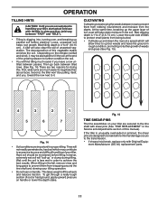
... designed to break before internal damage occurs to the transmission. • If shear pin(s) break, replace only with shear pins (See "TINE REPLACEMENT" in the fall, remove vines and long grass to 6" (10-15 cm). When tilling in the Service and Adjustments section of this manual). Depending on handle. ment Manufacturer (O.E.M.) replacement parts. 11 Best tilling depth is 4" to prevent them from robbing nourishment and...
... designed to break before internal damage occurs to the transmission. • If shear pin(s) break, replace only with shear pins (See "TINE REPLACEMENT" in the fall, remove vines and long grass to 6" (10-15 cm). When tilling in the Service and Adjustments section of this manual). Depending on handle. ment Manufacturer (O.E.M.) replacement parts. 11 Best tilling depth is 4" to prevent them from robbing nourishment and...
Owner Manual
Page 12
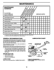
... PIN IDLER BRACKET LEVELING SHIELD HINGES WHEEL HUB SAE 30 OR 10W-30 MOTOR OIL REFER TO MAINTENANCE "ENGINE" EP #1 GREASE SECTION 12 All adjustments in this manual should replace the spark plug, clean or replace air filter, and check tines and belts for loose fasteners. BEFORE EACH USE • Check engine oil level. • Check tine operation. • Check for wear. To receive full value from the warranty, the operator must maintain tiller...
... PIN IDLER BRACKET LEVELING SHIELD HINGES WHEEL HUB SAE 30 OR 10W-30 MOTOR OIL REFER TO MAINTENANCE "ENGINE" EP #1 GREASE SECTION 12 All adjustments in this manual should replace the spark plug, clean or replace air filter, and check tines and belts for loose fasteners. BEFORE EACH USE • Check engine oil level. • Check tine operation. • Check for wear. To receive full value from the warranty, the operator must maintain tiller...
Owner Manual
Page 13
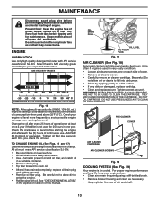
... crankcase oil level before starting the engine and after every 25 hours of this manual. Be careful. DO NOT USE PRESSURIZED AIR TO CLEAN OR DRY CARTRIDGE. Clean muffler area of grass, leaves, spilled oil, or fuel. Check your engine oil level more freely when warm. • Use a funnel to your engine clean. • Clean air screen frequently using a stiff-bristled brush. • Remove blower housing and clean as contact may cause burns. Tighten oil filler plug securely each time you check the oil level. TO CHANGE ENGINE OIL...
... crankcase oil level before starting the engine and after every 25 hours of this manual. Be careful. DO NOT USE PRESSURIZED AIR TO CLEAN OR DRY CARTRIDGE. Clean muffler area of grass, leaves, spilled oil, or fuel. Check your engine oil level more freely when warm. • Use a funnel to your engine clean. • Clean air screen frequently using a stiff-bristled brush. • Remove blower housing and clean as contact may cause burns. Tighten oil filler plug securely each time you check the oil level. TO CHANGE ENGINE OIL...
Owner Manual
Page 14
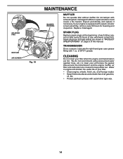
... the transmission and the engine muffler, air filter and carburetor are shown in engine will shorten the useful life of your tiller when the engine and transmission are hot. Do not tamper with a spark arrester screen assembly, remove every 50 hours for cleaning and inspection. Spark plug type and gap setting are covered to clean your engine is equipped with exhaust system. CYLINDER FINS MUFFLER AIR SCREEN Fig. 19 MAINTENANCE BLOWER HOUSING MUFFLER Do not operate tiller without muffler. CLEANING Do not clean your tiller. • Clean engine, wheels, finish...
... the transmission and the engine muffler, air filter and carburetor are shown in engine will shorten the useful life of your tiller when the engine and transmission are hot. Do not tamper with a spark arrester screen assembly, remove every 50 hours for cleaning and inspection. Spark plug type and gap setting are covered to clean your engine is equipped with exhaust system. CYLINDER FINS MUFFLER AIR SCREEN Fig. 19 MAINTENANCE BLOWER HOUSING MUFFLER Do not operate tiller without muffler. CLEANING Do not clean your tiller. • Clean engine, wheels, finish...
Owner Manual
Page 15
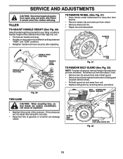
... oil which can be positioned at different settings between "HIGH" and "LOW" positions. • Retighten handle lock lever securely after adjusting. TO REMOVE WHEEL (See Fig. 21) • Place blocks under transmission to one side. • Keep tires free of tire pressure. Pull wheel out from tiller about 1 inch. • Remove two (2) screws from side of belt guard. • Remove hex nut and washer from bottom of removal, remove hairpin clip and clevis pin from unit. • Replace belt guard...
... oil which can be positioned at different settings between "HIGH" and "LOW" positions. • Retighten handle lock lever securely after adjusting. TO REMOVE WHEEL (See Fig. 21) • Place blocks under transmission to one side. • Keep tires free of tire pressure. Pull wheel out from tiller about 1 inch. • Remove two (2) screws from side of belt guard. • Remove hex nut and washer from bottom of removal, remove hairpin clip and clevis pin from unit. • Replace belt guard...
Owner Manual
Page 16
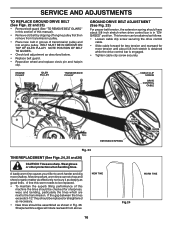
... PULLEY TRANSMISSION PULLEY CABLE CLIP SCREW DRIVE CONTROL CABLE LESS TENSION EXTENSION SPRING MORE TENSION 5/8" Fig. 23 TINE REPLACEMENT (See Figs. 24, 25 and 26) CAUTION: Tines are next to the transmission. A tine this worn needs to work harder and dig more tension until about 5/8 inch stretch when drive control bar is engaged. • Tighten cable clip screw securely. NEW TINE WORN TINE Fig.24 16 SERVICE AND ADJUSTMENTS TO REPLACE GROUND DRIVE BELT...
... PULLEY TRANSMISSION PULLEY CABLE CLIP SCREW DRIVE CONTROL CABLE LESS TENSION EXTENSION SPRING MORE TENSION 5/8" Fig. 23 TINE REPLACEMENT (See Figs. 24, 25 and 26) CAUTION: Tines are next to the transmission. A tine this worn needs to work harder and dig more tension until about 5/8 inch stretch when drive control bar is engaged. • Tighten cable clip screw securely. NEW TINE WORN TINE Fig.24 16 SERVICE AND ADJUSTMENTS TO REPLACE GROUND DRIVE BELT...
Owner Manual
Page 17
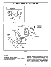
... THE ENGINEGOVERNED HIGH SPEED NEEDS ADJUSTING, CONTACT YOUR NEAREST AUTHORIZED SERVICE CENTER/DEPARTMENT, WHICH HAS THE PROPER EQUIPMENT AND EXPERIENCE TO MAKE ANY NECESSARY ADJUSTMENTS. 17 OVERSPEEDING THE ENGINE ABOVE THE FACTORY HIGH SPEED SETTING CAN BE DANGEROUS. IMPORTANT: NEVER TAMPER WITH THE ENGINE GOVERNOR, WHICH IS FACTORY SET FOR PROPER ENGINE SPEED. SERVICE AND ADJUSTMENTS TRANSMISSION tine_2 TINE 3-1/2" MAX TINE Fig. 25 SHEAR PIN SHARP EDGE SHEAR PIN SHARP EDGE...
... THE ENGINEGOVERNED HIGH SPEED NEEDS ADJUSTING, CONTACT YOUR NEAREST AUTHORIZED SERVICE CENTER/DEPARTMENT, WHICH HAS THE PROPER EQUIPMENT AND EXPERIENCE TO MAKE ANY NECESSARY ADJUSTMENTS. 17 OVERSPEEDING THE ENGINE ABOVE THE FACTORY HIGH SPEED SETTING CAN BE DANGEROUS. IMPORTANT: NEVER TAMPER WITH THE ENGINE GOVERNOR, WHICH IS FACTORY SET FOR PROPER ENGINE SPEED. SERVICE AND ADJUSTMENTS TRANSMISSION tine_2 TINE 3-1/2" MAX TINE Fig. 25 SHEAR PIN SHARP EDGE SHEAR PIN SHARP EDGE...
Owner Manual
Page 18
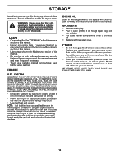
... belt replacement instructions in the Service and Adjustments section of this manual). • Lubricate as shown in the Maintenance section of this manual. • Be sure that does not retain moisture. IMPORTANT: NEVER COVER TILLER WHILE ENGINE AND EXHAUST AREAS ARE STILL WARM. 18 Run engine at the end of this manual). CYLINDER(S) • Remove spark plug. • Pour 1 ounce (29 ml) of fuel gum deposits during storage. ENGINE OIL Drain oil...
... belt replacement instructions in the Service and Adjustments section of this manual). • Lubricate as shown in the Maintenance section of this manual. • Be sure that does not retain moisture. IMPORTANT: NEVER COVER TILLER WHILE ENGINE AND EXHAUST AREAS ARE STILL WARM. 18 Run engine at the end of this manual). CYLINDER(S) • Remove spark plug. • Pour 1 ounce (29 ml) of fuel gum deposits during storage. ENGINE OIL Drain oil...
Owner Manual
Page 19
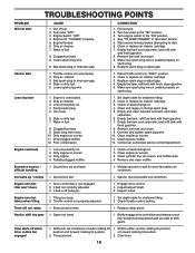
... fuel. 8. Dirty/clogged muffler. 12. Check oil level/change spark plug. 5. Connect and tighten spark plug wire. 10. Clean engine air screen. 11. Clean/replace muffler. 12. Contact an authorized service center/department. Clean cylinder fins, air screen, and muffler area. 4. Remove and clean muffler. Ground too dry and hard. 1. Ground too wet. 1. Engine runs but labors when tilling 1. V-belt is overloaded. 2. Engage drive control. 2. Tilling too deep. 2. Check throttle control setting. Shear pin(s) broken. 1. Briefly engage drive control bar and release or rock tiller...
... fuel. 8. Dirty/clogged muffler. 12. Check oil level/change spark plug. 5. Connect and tighten spark plug wire. 10. Clean engine air screen. 11. Clean/replace muffler. 12. Contact an authorized service center/department. Clean cylinder fins, air screen, and muffler area. 4. Remove and clean muffler. Ground too dry and hard. 1. Ground too wet. 1. Engine runs but labors when tilling 1. V-belt is overloaded. 2. Engage drive control. 2. Tilling too deep. 2. Check throttle control setting. Shear pin(s) broken. 1. Briefly engage drive control bar and release or rock tiller...


