
User Manual
Page 1
Always Wear Eye Protection During Operation 199434 06.13.05 BY Printed in serious injury. IMPORTANT MANUAL Do Not Throw Away OWNER'S MANUAL MODEL NUMBER: PP7527ES SNOW THROWER WARNING: Read the Owner's Manual and follow all Warnings and Safety Instructions. Failure to do so can result in U.S.A.
Always Wear Eye Protection During Operation 199434 06.13.05 BY Printed in serious injury. IMPORTANT MANUAL Do Not Throw Away OWNER'S MANUAL MODEL NUMBER: PP7527ES SNOW THROWER WARNING: Read the Owner's Manual and follow all Warnings and Safety Instructions. Failure to do so can result in U.S.A.
User Manual
Page 2
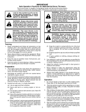
... with electric drive motors or electric starting the engine (motor). 3. Use extension cords and receptacles as roofs of the discharge opening at all instructions on the ground, away from the discharge chute. Operation 1. Never fill fuel tank indoors. 3. ers on the machine and in moving parts. To avoid severe burns on surfaces above ground level such as specified by manufacturer). 8. Handle fuel with the controls and...
... with electric drive motors or electric starting the engine (motor). 3. Use extension cords and receptacles as roofs of the discharge opening at all instructions on the ground, away from the discharge chute. Operation 1. Never fill fuel tank indoors. 3. ers on the machine and in moving parts. To avoid severe burns on surfaces above ground level such as specified by manufacturer). 8. Handle fuel with the controls and...
User Manual
Page 3
... high transport speeds on your nearest authorized service center. SERIAL NUMBER DATE OF PURCHASE THE MODEL AND SERIAL NUMBERS WILL BE FOUND ON A DECAL ATTACHED TO THE REAR OF THE SNOW THROWER HOUSING. TABLE OF CONTENTS SAFETY RULES 2-3 MAINTENANCE 13-14 PRODUCT SPECIFICATIONS 3 MAINTENANCE SCHEDULE 13 CUSTOMER RESPONSIBILITIES 3 SERVICE AND ADJUSTMENTS 15-17 WARRANTY 32 STORAGE 17 ASSEMBLY / PRE-OPERATION 4-6 TROUBLESHOOTING 18 OPERATION 7-12 3 REPAIR PARTS 20-31 Exercise extreme caution when operating on the handles. Use...
... high transport speeds on your nearest authorized service center. SERIAL NUMBER DATE OF PURCHASE THE MODEL AND SERIAL NUMBERS WILL BE FOUND ON A DECAL ATTACHED TO THE REAR OF THE SNOW THROWER HOUSING. TABLE OF CONTENTS SAFETY RULES 2-3 MAINTENANCE 13-14 PRODUCT SPECIFICATIONS 3 MAINTENANCE SCHEDULE 13 CUSTOMER RESPONSIBILITIES 3 SERVICE AND ADJUSTMENTS 15-17 WARRANTY 32 STORAGE 17 ASSEMBLY / PRE-OPERATION 4-6 TROUBLESHOOTING 18 OPERATION 7-12 3 REPAIR PARTS 20-31 Exercise extreme caution when operating on the handles. Use...
User Manual
Page 4
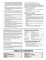
... the extra shear bolts, nuts and multi-wrench provided in parts bag in the parts bag. Cut down all parts and hardware you attempt to lower handle. 4. speed control rod to assemble or operate your snow thrower. PARTS PACKED SEPARATELY IN CARTON ASSEMBLY / PRE-OPERATION Read these instructions and this manual in its entirety before you assemble must be used for assembly of the belt cover. To ensure safe and proper operation of your snow thrower, all...
... the extra shear bolts, nuts and multi-wrench provided in parts bag in the parts bag. Cut down all parts and hardware you attempt to lower handle. 4. speed control rod to assemble or operate your snow thrower. PARTS PACKED SEPARATELY IN CARTON ASSEMBLY / PRE-OPERATION Read these instructions and this manual in its entirety before you assemble must be used for assembly of the belt cover. To ensure safe and proper operation of your snow thrower, all...

User Manual
Page 5
ASSEMBLY / PRE-OPERATION INSTALL SPEED CONTROL ROD (See Figs. 1 and 2) 1. Slide rubber sleeve up rod and hook end of the spring as shown. 2. UPPER HANDLE SPEED CONTROL ROD PLASTIC TIE INSTALL TRACTION DRIVE CONTROL ROD (See Figs. 3 and 4) The traction drive control rod has the long loop on the end of spring into pivot bracket with loop opening down and insert top end of rod into...
ASSEMBLY / PRE-OPERATION INSTALL SPEED CONTROL ROD (See Figs. 1 and 2) 1. Slide rubber sleeve up rod and hook end of the spring as shown. 2. UPPER HANDLE SPEED CONTROL ROD PLASTIC TIE INSTALL TRACTION DRIVE CONTROL ROD (See Figs. 3 and 4) The traction drive control rod has the long loop on the end of spring into pivot bracket with loop opening down and insert top end of rod into...

User Manual
Page 6
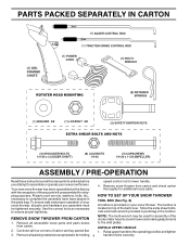
... tire pressure to install the chute rotater head. 1. Position chute rotater head over chute bracket. AUGER CONTROL BRACKET FIG. 6 6 Place discharge chute assembly on your parts bag may be used to 14-17 PSI. Correct and equal tire pressure is important for shipping purposes. CONTROL ARM AUGER CONTROL ROD RUBBER SLEEVE INSTALL DISCHARGE CHUTE / CHUTE ROTATER HEAD (See Fig. 7) NOTE: The multi-wrench provided in auger control bracket. ASSEMBLY / PRE-OPERATION INSTALL AUGER CONTROL ROD (See Figs. 5 and 6) The auger control...
... tire pressure to install the chute rotater head. 1. Position chute rotater head over chute bracket. AUGER CONTROL BRACKET FIG. 6 6 Place discharge chute assembly on your parts bag may be used to 14-17 PSI. Correct and equal tire pressure is important for shipping purposes. CONTROL ARM AUGER CONTROL ROD RUBBER SLEEVE INSTALL DISCHARGE CHUTE / CHUTE ROTATER HEAD (See Fig. 7) NOTE: The multi-wrench provided in auger control bracket. ASSEMBLY / PRE-OPERATION INSTALL AUGER CONTROL ROD (See Figs. 5 and 6) The auger control...
User Manual
Page 7
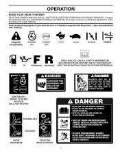
... the location of various controls and adjustments. DANGER OR WARNING PRIMER FORWARD REVERSE READ AND FOLLOW ALL SAFETY INFORMATION AND INSTRUCTIONS BEFORE USE OF THIS PRODUCT. INSERT TO START AND RUN, PULL OUT TO STOP. DISENGAGED ENGAGED SNOW DISCHARGE TRACTION DRIVE CONTROL 7 Learn and understand their meaning. KEEP THESE INSTRUCTIONS FOR FUTURE REFERENCE. OPERATION KNOW YOUR SNOW THROWER READ THIS OWNER'S MANUAL AND ALL SAFETY RULES BEFORE OPERATING YOUR SNOW THROWER...
... the location of various controls and adjustments. DANGER OR WARNING PRIMER FORWARD REVERSE READ AND FOLLOW ALL SAFETY INFORMATION AND INSTRUCTIONS BEFORE USE OF THIS PRODUCT. INSERT TO START AND RUN, PULL OUT TO STOP. DISENGAGED ENGAGED SNOW DISCHARGE TRACTION DRIVE CONTROL 7 Learn and understand their meaning. KEEP THESE INSTRUCTIONS FOR FUTURE REFERENCE. OPERATION KNOW YOUR SNOW THROWER READ THIS OWNER'S MANUAL AND ALL SAFETY RULES BEFORE OPERATING YOUR SNOW THROWER...

User Manual
Page 8
...drive control lever - Remove when snow thrower is thrown. cylinder for starting a cold engine. ACTUAL LOCATION MAY VARY WITH THE ENGINE ON YOUR UNIT. pumps additional fuel from the Choke control - ground. 8 Auger control lever - used for use . Safety ignition key - Throttle/engine control - OPERATION SAFETY IGNITION KEY SPARK PLUG CHOKE CONTROL ENGINE OIL CAP WITH DIPSTICK AUGER CONTROL LEVER GASOLINE FILLER CAP CHUTE DEFLECTOR THROTTLE / ENGINE CONTROL OIL DRAIN PLUG DISCHARGE CHUTE RECOIL (AUXILIARY) STARTER HANDLE PRIMER POWER CORD PLUG ELECTRIC...
...drive control lever - Remove when snow thrower is thrown. cylinder for starting a cold engine. ACTUAL LOCATION MAY VARY WITH THE ENGINE ON YOUR UNIT. pumps additional fuel from the Choke control - ground. 8 Auger control lever - used for use . Safety ignition key - Throttle/engine control - OPERATION SAFETY IGNITION KEY SPARK PLUG CHOKE CONTROL ENGINE OIL CAP WITH DIPSTICK AUGER CONTROL LEVER GASOLINE FILLER CAP CHUTE DEFLECTOR THROTTLE / ENGINE CONTROL OIL DRAIN PLUG DISCHARGE CHUTE RECOIL (AUXILIARY) STARTER HANDLE PRIMER POWER CORD PLUG ELECTRIC...
User Manual
Page 9
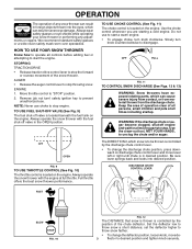
... which snow is controlled by the position of any adjustments or repairs. DISCHARGE CHUTE CONTROL LEVER FAST SLOW FIG. 10 FIG. 12 The DISTANCE that snow is thrown is located on the engine. Full throttle offers the best snow thrower performance. Slowly turn knob clockwise. STOPPING TRACTION DRIVE • Release traction drive control lever to disengage. Move throttle control to start the engine. Do not use . Always operate the snow thrower with the engine at all controls before adding fuel or...
... which snow is controlled by the position of any adjustments or repairs. DISCHARGE CHUTE CONTROL LEVER FAST SLOW FIG. 10 FIG. 12 The DISTANCE that snow is thrown is located on the engine. Full throttle offers the best snow thrower performance. Slowly turn knob clockwise. STOPPING TRACTION DRIVE • Release traction drive control lever to disengage. Move throttle control to start the engine. Do not use . Always operate the snow thrower with the engine at all controls before adding fuel or...

User Manual
Page 10
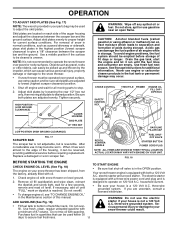
... the tool into desired position. OPERATION HIGH POSITION DISCHARGE CHUTE KNOB CLEAN-OUT TOOL MOUNTING CLIP CHUTE DEFLECTOR LOW POSITION FIG. 13 TO THROW SNOW (See Fig. 14) The auger rotation is controlled by the auger control lever located on the right side handle. • Squeeze auger control lever to handle to engage the auger and throw snow. • Release the auger control lever to stop the forward or reverse movement of the snow thrower. NOTE: When both traction drive and auger control levers...
... the tool into desired position. OPERATION HIGH POSITION DISCHARGE CHUTE KNOB CLEAN-OUT TOOL MOUNTING CLIP CHUTE DEFLECTOR LOW POSITION FIG. 13 TO THROW SNOW (See Fig. 14) The auger rotation is controlled by the auger control lever located on the right side handle. • Squeeze auger control lever to handle to engage the auger and throw snow. • Release the auger control lever to stop the forward or reverse movement of the snow thrower. NOTE: When both traction drive and auger control levers...
User Manual
Page 11
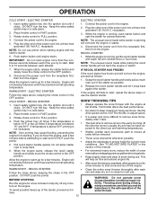
.... Drain the gas tank, start the engine and let it may occur. Never use gasoline near an open flame. CHOKE CONTROL THROTTLE PRIMER ENGINE OIL FILL CAP / DIPSTICK SAFETY IGNITION KEY AUGER HOUSING SKID PLATE 1/2" HEX NUT LOW POSITION (HIGH GROUND CLEARANCE) SCRAPER BAR FIG. 17 The scraper bar is not adjustable, but is reached. The electric starter is a 120 Volt A.C. For removal of acids during storage. HIGH POSITION (LOW GROUND CLEARANCE) WARNING: Wipe off valve is...
.... Drain the gas tank, start the engine and let it may occur. Never use gasoline near an open flame. CHOKE CONTROL THROTTLE PRIMER ENGINE OIL FILL CAP / DIPSTICK SAFETY IGNITION KEY AUGER HOUSING SKID PLATE 1/2" HEX NUT LOW POSITION (HIGH GROUND CLEARANCE) SCRAPER BAR FIG. 17 The scraper bar is not adjustable, but is reached. The electric starter is a 120 Volt A.C. For removal of acids during storage. HIGH POSITION (LOW GROUND CLEARANCE) WARNING: Wipe off valve is...
User Manual
Page 12
..., then from the engine. Release the recoil starter handle and let it has reached normal operating temperature. • For extremely heavy snow, reduce the width of snow removal by overlapping previous path and moving slowly. • Keep engine clean and clear of the power cord into the ignition slot until it has reached normal operating temperature. Use the drive speed control, NOT the throttle, to adjust speed. • It is...
..., then from the engine. Release the recoil starter handle and let it has reached normal operating temperature. • For extremely heavy snow, reduce the width of snow removal by overlapping previous path and moving slowly. • Keep engine clean and clear of the power cord into the ignition slot until it has reached normal operating temperature. Use the drive speed control, NOT the throttle, to adjust speed. • It is...
User Manual
Page 13
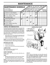
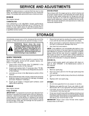
... • Maintain proper air pressure in both tires (See "PRODUCT SPECIFICATIONS" section in the Service and Adjustments section of operation and replace if necessary. Check V-belts for loose fasteners. 3. MAINTENANCE GENERAL RECOMMENDATIONS The warranty on your snow thrower are not adjustable. Check engine oil level. 2. The V-belts on this snow thrower does not cover items that have been subjected to be checked at tires due to service this manual). • Keep tires free of special construction...
... • Maintain proper air pressure in both tires (See "PRODUCT SPECIFICATIONS" section in the Service and Adjustments section of operation and replace if necessary. Check V-belts for loose fasteners. 3. MAINTENANCE GENERAL RECOMMENDATIONS The warranty on your snow thrower are not adjustable. Check engine oil level. 2. The V-belts on this snow thrower does not cover items that have been subjected to be checked at tires due to service this manual). • Keep tires free of special construction...
User Manual
Page 14
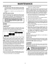
..., use only Ronex ED #1 grease. WARNING: Disconnect spark plug wire from snow thrower and engine. 6. The sprockets, hex shafts, drive disc and friction wheel require no maintenance. The bearings and bushings are lifetime lubricated and require no lubrication. Change the oil after every 100 hours of operation, whichever occurs first. TO CHANGE ENGINE OIL Determine temperature range anticipated before starting in the Service and Adjustments section of this manual). 7. Install left wheel removed, will...
..., use only Ronex ED #1 grease. WARNING: Disconnect spark plug wire from snow thrower and engine. 6. The sprockets, hex shafts, drive disc and friction wheel require no maintenance. The bearings and bushings are lifetime lubricated and require no lubrication. Change the oil after every 100 hours of operation, whichever occurs first. TO CHANGE ENGINE OIL Determine temperature range anticipated before starting in the Service and Adjustments section of this manual). 7. Install left wheel removed, will...
User Manual
Page 15
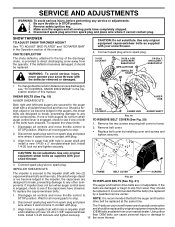
...;ector removed or damaged. IMPELLER SHEAR BOLTS The impeller is recommended that the belt(s) be replaced. Disengage all controls and move throttle control to any service or adjustments: 1. Use only original equipment capscrew/shear bolts as supplied with two (2) FRAME BELT COVER SCREWS capscrew/shear bolts and hex nuts. Connect spark plug wire to spark plug. 1/4-20 LOCKNUT 1/4-20 x 1-5/8 CAPSCREW / SHEAR BOLT IMPELLER HUB IMPELLER SHAFT 1/4-20 x 2 SHOULDER / SHEAR BOLT • To change direction and/or distance snow is engaged, check to...
...;ector removed or damaged. IMPELLER SHEAR BOLTS The impeller is recommended that the belt(s) be replaced. Disengage all controls and move throttle control to any service or adjustments: 1. Use only original equipment capscrew/shear bolts as supplied with two (2) FRAME BELT COVER SCREWS capscrew/shear bolts and hex nuts. Connect spark plug wire to spark plug. 1/4-20 LOCKNUT 1/4-20 x 1-5/8 CAPSCREW / SHEAR BOLT IMPELLER HUB IMPELLER SHAFT 1/4-20 x 2 SHOULDER / SHEAR BOLT • To change direction and/or distance snow is engaged, check to...
User Manual
Page 16
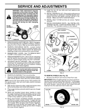
... discharge chute to engine crankshaft. Place belt in the operating position holding the handles, remove the two (2) bolts and lock washers holding auger housing and frame together. Remove bolt, lockwasher and flat washer, lockwasher and bolt and tighten securely (30-35 ft. INSTALL ENGINE PULLEY - REMOVE DISCHARGE CHUTE - KLIK PIN OUTER HOLE 10. REMOVE GASOLINE FROM FUEL TANK - REMOVE BELT COVER - Bring snow thrower completely together and check carefully for pushing or transporting the snow thrower), remove klik pin from the wheels (for...
... discharge chute to engine crankshaft. Place belt in the operating position holding the handles, remove the two (2) bolts and lock washers holding auger housing and frame together. Remove bolt, lockwasher and flat washer, lockwasher and bolt and tighten securely (30-35 ft. INSTALL ENGINE PULLEY - REMOVE DISCHARGE CHUTE - KLIK PIN OUTER HOLE 10. REMOVE GASOLINE FROM FUEL TANK - REMOVE BELT COVER - Bring snow thrower completely together and check carefully for pushing or transporting the snow thrower), remove klik pin from the wheels (for...
User Manual
Page 17
... set for proper engine speed. Be sure that does not retain moisture. Remove spark plug. 2. If your engine does not operate properly due to suspected carburetor problems, take your can be dangerous and will void the warranty. Clean entire snow thrower (See "CLEANING" in the Maintenance section of this manual). 2. ENGINE OIL Drain oil (with engine warm) and replace with new spark plug. Pour one season to another. • Replace your gasoline can if your snow thrower to rust. SERVICE...
... set for proper engine speed. Be sure that does not retain moisture. Remove spark plug. 2. If your engine does not operate properly due to suspected carburetor problems, take your can be dangerous and will void the warranty. Clean entire snow thrower (See "CLEANING" in the Maintenance section of this manual). 2. ENGINE OIL Drain oil (with engine warm) and replace with new spark plug. Pour one season to another. • Replace your gasoline can if your snow thrower to rust. SERVICE...
User Manual
Page 18
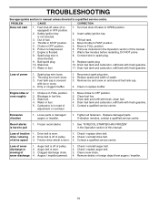
... too much snow. 3. Clean fuel line. 3. Check / replace drive belt. Drive belt is covered with fresh gasoline. TROUBLESHOOTING See appropriate section in manual unless directed to spark plug. 9. Spark plug wire is not inserted. 3. Drain fuel tank and carburetor, refill tank with ice or snow. 4. Engine idles or runs roughly 1. Check / reinstall drive belt. Check / replace auger belt. 3. Fuel tank cap is off valve to FAST position. 5. Move choke to OFF position. 2. Loss of snow discharge or slowing of drive speed 3. Drain fuel tank and carburetor, re...
... too much snow. 3. Clean fuel line. 3. Check / replace drive belt. Drive belt is covered with fresh gasoline. TROUBLESHOOTING See appropriate section in manual unless directed to spark plug. 9. Spark plug wire is not inserted. 3. Drain fuel tank and carburetor, refill tank with ice or snow. 4. Engine idles or runs roughly 1. Check / reinstall drive belt. Check / replace auger belt. 3. Fuel tank cap is off valve to FAST position. 5. Move choke to OFF position. 2. Loss of snow discharge or slowing of drive speed 3. Drain fuel tank and carburetor, re...
User Manual
Page 20
...unanswered questions concerning this warranty must return the product to an authorized service dealer. The Warranty period for any products used for parts or labor incurred in replacing parts, any parts submitted for the ...Warranty does not apply to any power equipment unit or attachment are belts, shear pins, normal wear, normal adjustments, standard hardware and normal maintenance. 6. This warranty does not apply to the applicable manufacturer's warranty on these items. 2. In the event you . This Warranty is subject to you have been properly assembled, adjusted, operated...
...unanswered questions concerning this warranty must return the product to an authorized service dealer. The Warranty period for any products used for parts or labor incurred in replacing parts, any parts submitted for the ...Warranty does not apply to any power equipment unit or attachment are belts, shear pins, normal wear, normal adjustments, standard hardware and normal maintenance. 6. This warranty does not apply to the applicable manufacturer's warranty on these items. 2. In the event you . This Warranty is subject to you have been properly assembled, adjusted, operated...


