
User Manual
Page 2
...of the discharge opening at all instructions on slippery surfaces. 4. Keep clear of residences, garages, porches or other engine parts become extremely hot during operation or while performing an adjustment or repair to protect eyes from foreign objects that will improve ...thrower is highly flammable (f) Keep the nozzle in order to prevent accidental starting the engine (motor). 3. WARNING: Snow throwers have exposed rotating parts, which can get caught in serious injury. Read, understand and follow all times. (a) Use an approved fuel container. 2. Disengage all doormats...
...of the discharge opening at all instructions on slippery surfaces. 4. Keep clear of residences, garages, porches or other engine parts become extremely hot during operation or while performing an adjustment or repair to protect eyes from foreign objects that will improve ...thrower is highly flammable (f) Keep the nozzle in order to prevent accidental starting the engine (motor). 3. WARNING: Snow throwers have exposed rotating parts, which can get caught in serious injury. Read, understand and follow all times. (a) Use an approved fuel container. 2. Disengage all doormats...
User Manual
Page 3
... cleaning, repairing or inspecting the snow thrower, stop the engine and make certain the collector/impeller and all moving parts have competent, well-trained technicians and the proper tools to give best possible dependability and performance. Do not overload ...PRODUCT SPECIFICATIONS 3 SERVICE AND ADJUSTMENTS 16-18 CUSTOMER RESPONSIBILITIES 3 STORAGE 19 ASSEMBLY / PRE-OPERATION 5-7 TROUBLESHOOTING 20 OPERATION 8-13 REPAIR PARTS 21-39 MAINTENANCE SCHEDULE 14 WARRANTY BACK COVER 3 Always use your nearest authorized service center. Look behind and use . 14....
... cleaning, repairing or inspecting the snow thrower, stop the engine and make certain the collector/impeller and all moving parts have competent, well-trained technicians and the proper tools to give best possible dependability and performance. Do not overload ...PRODUCT SPECIFICATIONS 3 SERVICE AND ADJUSTMENTS 16-18 CUSTOMER RESPONSIBILITIES 3 STORAGE 19 ASSEMBLY / PRE-OPERATION 5-7 TROUBLESHOOTING 20 OPERATION 8-13 REPAIR PARTS 21-39 MAINTENANCE SCHEDULE 14 WARRANTY BACK COVER 3 Always use your nearest authorized service center. Look behind and use . 14....

User Manual
Page 4
PARTS PACKED SEPARATELY IN CARTON (1) POWER CORD (198563) (1) MULTIWRENCH (180684) (3) RETAINER SPRINGS (169675) (2) FLAT WASHERS (2) SHEAR BOLTS 1/4-20 x 1-3/4 (192090) (2) LOCKNUTS 1/4-20 (73800400) (2) CARRIAGE BOLTS 3/8-16 x 2.25 (2) HANDLE KNOBS SAFTEY IGNITION KEY(S) (422663) (1) WASHER 3/8 (19131316) (1) LOCKNUT 3/8 (73800600) (1) LOCKNUT 5/16-18 (751153) (1) CARRIAGE BOLT 5/16-18 x 5/8 (72250505) (1) LOCKNUT 1/4-20 (191730) (1) SHOULDER BOLT 1/4-20 (179829) (1) SPRING (184505) 4
PARTS PACKED SEPARATELY IN CARTON (1) POWER CORD (198563) (1) MULTIWRENCH (180684) (3) RETAINER SPRINGS (169675) (2) FLAT WASHERS (2) SHEAR BOLTS 1/4-20 x 1-3/4 (192090) (2) LOCKNUTS 1/4-20 (73800400) (2) CARRIAGE BOLTS 3/8-16 x 2.25 (2) HANDLE KNOBS SAFTEY IGNITION KEY(S) (422663) (1) WASHER 3/8 (19131316) (1) LOCKNUT 3/8 (73800600) (1) LOCKNUT 5/16-18 (751153) (1) CARRIAGE BOLT 5/16-18 x 5/8 (72250505) (1) LOCKNUT 1/4-20 (191730) (1) SHOULDER BOLT 1/4-20 (179829) (1) SPRING (184505) 4
User Manual
Page 5
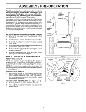
...(2) plastic ties securing the upper handle to the operating position and tighten handle knobs securely. The toolbox is provided on top of those parts left unassembled for shipping purposes. Remove plastic tie securing rod to the pallet. 4. Remove the two (2) screws securing the auger housing to.... LOWER HANDLE FIG. 1 SPEED CONTROL ROD RETAINER SPRING SPEED CONTROL BRACKET SPEED CONTROL LEVER FIG. 2 5 Remove all accessible loose parts and parts boxes from carton and check carton thoroughly for assembly of the product. Use to secure upper handle to assemble or operate your snow ...
...(2) plastic ties securing the upper handle to the operating position and tighten handle knobs securely. The toolbox is provided on top of those parts left unassembled for shipping purposes. Remove plastic tie securing rod to the pallet. 4. Remove the two (2) screws securing the auger housing to.... LOWER HANDLE FIG. 1 SPEED CONTROL ROD RETAINER SPRING SPEED CONTROL BRACKET SPEED CONTROL LEVER FIG. 2 5 Remove all accessible loose parts and parts boxes from carton and check carton thoroughly for assembly of the product. Use to secure upper handle to assemble or operate your snow ...

User Manual
Page 6
ASSEMBLY / PRE-OPERATION INSTALL TRACTION DRIVE CONTROL ROD (See Figs. 3 and 4) The traction drive control rod is installed on rod and insert end of parts and retrieve the auger control rod from bag of rod into hole in drive control bracket. Secure with retainer spring. Slide straight rod end through ...
ASSEMBLY / PRE-OPERATION INSTALL TRACTION DRIVE CONTROL ROD (See Figs. 3 and 4) The traction drive control rod is installed on rod and insert end of parts and retrieve the auger control rod from bag of rod into hole in drive control bracket. Secure with retainer spring. Slide straight rod end through ...

User Manual
Page 7
... THREADED STUD ROTATOR HEAD MOUNTING BRACKET REMOTE CABLE BRACKET 5/16-18 LOCKNUT FIG. 8 CHUTE DEFLECTOR CONTROL LEVER FIG. 9 CHECK TIRE PRESSURE The tires on your parts bag may be loose on threaded stud and tighten securely. Install remote cable bracket to install the chute rotator head. 1. With chute rotator head and...
... THREADED STUD ROTATOR HEAD MOUNTING BRACKET REMOTE CABLE BRACKET 5/16-18 LOCKNUT FIG. 8 CHUTE DEFLECTOR CONTROL LEVER FIG. 9 CHECK TIRE PRESSURE The tires on your parts bag may be loose on threaded stud and tighten securely. Install remote cable bracket to install the chute rotator head. 1. With chute rotator head and...

User Manual
Page 10
... a warm engine. • To engage choke, rotate lever to stop throwing snow. TO CONTROL SNOW DISCHARGE (See Fig. 13) WARNING: Snow throwers have exposed rotating parts, which can result in the OPEN position. Keep the area of operation clear of all persons, small children and pets at all moving... parts to throw snow farther. • Press downward on chute deflector control lever and move lever left or right until chute is located on discharge chute ...
... a warm engine. • To engage choke, rotate lever to stop throwing snow. TO CONTROL SNOW DISCHARGE (See Fig. 13) WARNING: Snow throwers have exposed rotating parts, which can result in the OPEN position. Keep the area of operation clear of all persons, small children and pets at all moving... parts to throw snow farther. • Press downward on chute deflector control lever and move lever left or right until chute is located on discharge chute ...

User Manual
Page 11
... CHUTE CLEAN-OUT TOOL MOUNTING CLIP • Slower speeds are for heavier snow and faster speeds are disengaged and the auger/impeller and all moving parts have stopped. TRACTION DRIVE CONTROL LEVER DRIVE SPEED CONTROL LEVER FIG. 16 POWER STEERING OPERATION (See Fig. 17) Steering triggers are familiar with ice and...
... CHUTE CLEAN-OUT TOOL MOUNTING CLIP • Slower speeds are for heavier snow and faster speeds are disengaged and the auger/impeller and all moving parts have stopped. TRACTION DRIVE CONTROL LEVER DRIVE SPEED CONTROL LEVER FIG. 16 POWER STEERING OPERATION (See Fig. 17) Steering triggers are familiar with ice and...
User Manual
Page 12
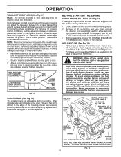
...worn almost to assure fuel freshness. Purchase fuel in your snow thrower has been shipped from the factory already filled with snow thrower on your parts bag may become worn. Use fresh fuel next season. Adjust skid plates evenly to stop. 2. ON / OFF SWITCH CHOKE CONTROL RECOIL (...THEIR TYPICAL LOCATION. To avoid engine problems, the fuel system should be picked up and thrown by loosening the hex nuts, then moving parts to proper height for all moving skid plate to desired position. ACTUAL LOCATION MAY VARY WITH ENGINE ON YOUR UNIT. BEFORE STARTING THE...
...worn almost to assure fuel freshness. Purchase fuel in your snow thrower has been shipped from the factory already filled with snow thrower on your parts bag may become worn. Use fresh fuel next season. Adjust skid plates evenly to stop. 2. ON / OFF SWITCH CHOKE CONTROL RECOIL (...THEIR TYPICAL LOCATION. To avoid engine problems, the fuel system should be picked up and thrown by loosening the hex nuts, then moving parts to proper height for all moving skid plate to desired position. ACTUAL LOCATION MAY VARY WITH ENGINE ON YOUR UNIT. BEFORE STARTING THE...

User Manual
Page 13
... power until engine starts. Use the drive speed control, NOT the ON / OFF switch, to operate on the engine. See "TO ADJUST SKID PLATES" in parts bag) into ignition slot until it has reached normal operating temperature. This will not develop full power until it snap back against the starter. receptacle...
... power until engine starts. Use the drive speed control, NOT the ON / OFF switch, to operate on the engine. See "TO ADJUST SKID PLATES" in parts bag) into ignition slot until it has reached normal operating temperature. This will not develop full power until it snap back against the starter. receptacle...
User Manual
Page 14
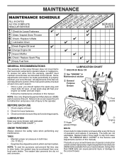
...belts if they are functioning properly. and corrosion. 14 Some adjustments will help your than OEM belts can cause the unit to local parts dealer. Check for deterioration and wear after every 50 hours maintenance. The belts on this manual should be checked at least once each... other to slow leaks, tire sealant may be sure they begin to the operator. NOTE: Use only Original Equipment Manufacturer (OEM) parts to be purchased from the warranty, operator must maintain snow thrower as instructed in Maintenance section General Purpose Grease Pivot points BEFORE EACH USE...
...belts if they are functioning properly. and corrosion. 14 Some adjustments will help your than OEM belts can cause the unit to local parts dealer. Check for deterioration and wear after every 50 hours maintenance. The belts on this manual should be checked at least once each... other to slow leaks, tire sealant may be sure they begin to the operator. NOTE: Use only Original Equipment Manufacturer (OEM) parts to be purchased from the warranty, operator must maintain snow thrower as instructed in Maintenance section General Purpose Grease Pivot points BEFORE EACH USE...

User Manual
Page 16
... sheared. Disconnect spark plug wire from spark plug. Disengage all moving parts to stop . 2. Align hole in auger hub with hole in impeller shaft and install two (2) new 1/4-20 x 1-5/8" capscrew/shear bolts. Insert safety ignition key and ... plug. If impeller does not turn when auger control lever is engaged, check to STOP position. To replace the capscrew/shear bolts: 1. Disengage all moving parts to any other components. Place wire where it cannot come in contact with plug. CAUTION: Do not substitute. Insert safety ignition key and reconnect spark...
... sheared. Disconnect spark plug wire from spark plug. Disengage all moving parts to stop . 2. Align hole in auger hub with hole in impeller shaft and install two (2) new 1/4-20 x 1-5/8" capscrew/shear bolts. Insert safety ignition key and ... plug. If impeller does not turn when auger control lever is engaged, check to STOP position. To replace the capscrew/shear bolts: 1. Disengage all moving parts to any other components. Place wire where it cannot come in contact with plug. CAUTION: Do not substitute. Insert safety ignition key and reconnect spark...
User Manual
Page 18
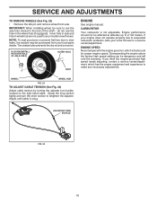
... closest to a service center/department. SERVICE AND ADJUSTMENTS TO REMOVE WHEELS (See Fig. 23) • Remove the klik pin and remove wheel from your local parts dealer.
... closest to a service center/department. SERVICE AND ADJUSTMENTS TO REMOVE WHEELS (See Fig. 23) • Remove the klik pin and remove wheel from your local parts dealer.
User Manual
Page 19
... if necessary (See "TO REPLACE BELTS" in the Service and Adjustments section of this manual. 4. Be sure that does not retain moisture. Inspect moving parts for damage, breakage and wear. Touch up all nuts, bolts, screws, and pins are empty. • Never use plastic. Also, alcohol blended fuels...to form and will cause problems. • If possible, store your snow thrower with clean engine oil. (See "ENGINE" in essential fuel system parts such as on stabilizer container. NOTE: Fuel stabilizer is still warm. 19 Always follow the mix ratio found on a furnace, water heater, clothes...
... if necessary (See "TO REPLACE BELTS" in the Service and Adjustments section of this manual. 4. Be sure that does not retain moisture. Inspect moving parts for damage, breakage and wear. Touch up all nuts, bolts, screws, and pins are empty. • Never use plastic. Also, alcohol blended fuels...to form and will cause problems. • If possible, store your snow thrower with clean engine oil. (See "ENGINE" in essential fuel system parts such as on stabilizer container. NOTE: Fuel stabilizer is still warm. 19 Always follow the mix ratio found on a furnace, water heater, clothes...
User Manual
Page 20
... Empty fuel tank & carburetor, refill with fresh, clean gasoline. 11. Contact an authorized service center/department. Excessive vibration 1. Replace damaged parts. Drive belt is in FULL position. 2. Drive belt is worn. 3. Augers / impeller jammed. 1. Bad spark plug. 10. Stale ... starter is disconnected. 9. Clogged discharge chute. 4. Loss of fuel. 4. Move choke to an authorized service center/department. Loose parts or damaged augers or impeller. 1. If vibration remains, contact an authorized service center/department. Check / replace auger belt. 3. ...
... Empty fuel tank & carburetor, refill with fresh, clean gasoline. 11. Contact an authorized service center/department. Excessive vibration 1. Replace damaged parts. Drive belt is in FULL position. 2. Drive belt is worn. 3. Augers / impeller jammed. 1. Bad spark plug. 10. Stale ... starter is disconnected. 9. Clogged discharge chute. 4. Loss of fuel. 4. Move choke to an authorized service center/department. Loose parts or damaged augers or impeller. 1. If vibration remains, contact an authorized service center/department. Check / replace auger belt. 3. ...

User Manual
Page 21
... 3 2 411939 BEARING PLUG 3 179582 SCREW 5/16−18 X 1.00 01.07.024-B NOTE: All component dimensions given in U.S. MODEL PP208EPS24L (96198003801) AUGER HOUSING / IMPELLER ASSEMBLY 1 3 (5x) 4 (5x) 2 01.07.001-A KEY NO. 1 2 3 4 PART NO. 404928X428 404931X431 72270505 155377 DESCRIPTION AUGER HOUSING SCRAPER BAR CARRIAGE BOLT 5/16−18 X .625 NUT 5/16−...
... 3 2 411939 BEARING PLUG 3 179582 SCREW 5/16−18 X 1.00 01.07.024-B NOTE: All component dimensions given in U.S. MODEL PP208EPS24L (96198003801) AUGER HOUSING / IMPELLER ASSEMBLY 1 3 (5x) 4 (5x) 2 01.07.001-A KEY NO. 1 2 3 4 PART NO. 404928X428 404931X431 72270505 155377 DESCRIPTION AUGER HOUSING SCRAPER BAR CARRIAGE BOLT 5/16−18 X .625 NUT 5/16−...

User Manual
Page 22
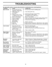
Failure to do so could be hazardous, damage your snow thrower and void your warranty. 22 inches. 1 inch = 25.4 mm IMPORTANT: Use only Original Equipment Manufacturer (O.E.M.) replacement parts. REPAIR PARTS SNOW THROWER - MODEL PP208EPS24L (96198003801) AUGER HOUSING / IMPELLER ASSEMBLY 5 15 14 4 11 6 11 16 12 13 11 3 12 10 11 7 8 17 1 9 37 2 9 9 33 37 32 34 30 31 31 29 28 26 27 36 20 21 22 23 25 35 24 23 22 21 18 19 2 (EXPLODED) 01.07.026-D NOTE: All component dimensions given in U.S.
Failure to do so could be hazardous, damage your snow thrower and void your warranty. 22 inches. 1 inch = 25.4 mm IMPORTANT: Use only Original Equipment Manufacturer (O.E.M.) replacement parts. REPAIR PARTS SNOW THROWER - MODEL PP208EPS24L (96198003801) AUGER HOUSING / IMPELLER ASSEMBLY 5 15 14 4 11 6 11 16 12 13 11 3 12 10 11 7 8 17 1 9 37 2 9 9 33 37 32 34 30 31 31 29 28 26 27 36 20 21 22 23 25 35 24 23 22 21 18 19 2 (EXPLODED) 01.07.026-D NOTE: All component dimensions given in U.S.

User Manual
Page 23
... could be hazardous, damage your snow thrower and void your warranty. 23 inches. 1 inch = 25.4 mm IMPORTANT: Use only Original Equipment Manufacturer (O.E.M.) replacement parts. REPAIR PARTS SNOW THROWER - MODEL PP208EPS24L (96198003801) AUGER HOUSING / IMPELLER ASSEMBLY KEY NO. 1 2 3 4 5 6 7 8 9 10 11 12 13 14 15 16 17 18 19 20 21... 22 23 24 25 26 27 28 29 30 31 32 33 34 35 36 37 PART NO. 175321X431 427148 188909 427146 175322 178675X431 192199 ...
... could be hazardous, damage your snow thrower and void your warranty. 23 inches. 1 inch = 25.4 mm IMPORTANT: Use only Original Equipment Manufacturer (O.E.M.) replacement parts. REPAIR PARTS SNOW THROWER - MODEL PP208EPS24L (96198003801) AUGER HOUSING / IMPELLER ASSEMBLY KEY NO. 1 2 3 4 5 6 7 8 9 10 11 12 13 14 15 16 17 18 19 20 21... 22 23 24 25 26 27 28 29 30 31 32 33 34 35 36 37 PART NO. 175321X431 427148 188909 427146 175322 178675X431 192199 ...

User Manual
Page 24
... be hazardous, damage your snow thrower and void your warranty. 24 inches. 1 inch = 25.4 mm IMPORTANT: Use only Original Equipment Manufacturer (O.E.M.) replacement parts. MODEL PP208EPS24L (96198003801) AUGER HOUSING / IMPELLER ASSEMBLY 2 1 KEY NO. 1 2 PART NO. 420493X421 420494X421 DESCRIPTION AUGER ASSEMBLY LH 24 AUGER ASSEMBLY RH 24 01.07.017-A 2 1 3 3 1 2 01.11.003-B KEY NO...
... be hazardous, damage your snow thrower and void your warranty. 24 inches. 1 inch = 25.4 mm IMPORTANT: Use only Original Equipment Manufacturer (O.E.M.) replacement parts. MODEL PP208EPS24L (96198003801) AUGER HOUSING / IMPELLER ASSEMBLY 2 1 KEY NO. 1 2 PART NO. 420493X421 420494X421 DESCRIPTION AUGER ASSEMBLY LH 24 AUGER ASSEMBLY RH 24 01.07.017-A 2 1 3 3 1 2 01.11.003-B KEY NO...
User Manual
Page 25
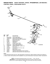
...All component dimensions given in U.S. inches. 1 inch = 25.4 mm IMPORTANT: Use only Original Equipment Manufacturer (O.E.M.) replacement parts. ITEMS 15 AND 16 ARE SERVICE PART NUMBERS TO ALLOW PURCHASE OF INDIVIDUAL ITEMS IF NECESSARY. MODEL PP208EPS24L (96198003801) CONTROL PANEL / DISCHARGE CHUTE 5 7 15 3 16 *14 *11 2 4 6 *10 KEY NO.... 1 2 3 4 5 6 7 8 9 *10 *11 *12 *13 *14 15 16 PART NO. 435023X428 178633X428 420673 420325 414280 ...
...All component dimensions given in U.S. inches. 1 inch = 25.4 mm IMPORTANT: Use only Original Equipment Manufacturer (O.E.M.) replacement parts. ITEMS 15 AND 16 ARE SERVICE PART NUMBERS TO ALLOW PURCHASE OF INDIVIDUAL ITEMS IF NECESSARY. MODEL PP208EPS24L (96198003801) CONTROL PANEL / DISCHARGE CHUTE 5 7 15 3 16 *14 *11 2 4 6 *10 KEY NO.... 1 2 3 4 5 6 7 8 9 *10 *11 *12 *13 *14 15 16 PART NO. 435023X428 178633X428 420673 420325 414280 ...


