

User Manual
Page 2
...striking a foreign object, stop the engine (motor), remove the wire from the truck or trailer and refuel it cannot contact plug in moving parts. BECOME ALERT!!! Caution should start to vibrate abnormally, stop the unit and disengage the controls quickly. 2. Do not use of residences, ...wearing adequate winter garments. WARNING: Always disconnect spark plug wire and place it where it on sidewalks, driveways and other engine parts become extremely hot during operation or while performing an adjustment or repair to avoid slipping or falling, especially when operating the snow...
...striking a foreign object, stop the engine (motor), remove the wire from the truck or trailer and refuel it cannot contact plug in moving parts. BECOME ALERT!!! Caution should start to vibrate abnormally, stop the unit and disengage the controls quickly. 2. Do not use of residences, ...wearing adequate winter garments. WARNING: Always disconnect spark plug wire and place it where it on sidewalks, driveways and other engine parts become extremely hot during operation or while performing an adjustment or repair to avoid slipping or falling, especially when operating the snow...
User Manual
Page 3
... service or repair this unit. When cleaning, repairing or inspecting the snow thrower, stop the engine and make certain the collector/impeller and all moving parts have competent, well-trained technicians and the proper tools to +40°F) SAE 0W-30 (below 0°F) Oil Capacity: 26 Ounces (0,74 Liters) Spark ...CONTENTS SAFETY RULES 2-3 MAINTENANCE SCHEDULE 14 PRODUCT SPECIFICATIONS 3 SERVICE AND ADJUSTMENTS 16-18 CUSTOMER RESPONSIBILITIES 3 STORAGE 18 ASSEMBLY / PRE-OPERATION 5-7 TROUBLESHOOTING 19 OPERATION 8-13 REPAIR PARTS 20-38 MAINTENANCE 14-15 3 WARRANTY 40
... service or repair this unit. When cleaning, repairing or inspecting the snow thrower, stop the engine and make certain the collector/impeller and all moving parts have competent, well-trained technicians and the proper tools to +40°F) SAE 0W-30 (below 0°F) Oil Capacity: 26 Ounces (0,74 Liters) Spark ...CONTENTS SAFETY RULES 2-3 MAINTENANCE SCHEDULE 14 PRODUCT SPECIFICATIONS 3 SERVICE AND ADJUSTMENTS 16-18 CUSTOMER RESPONSIBILITIES 3 STORAGE 18 ASSEMBLY / PRE-OPERATION 5-7 TROUBLESHOOTING 19 OPERATION 8-13 REPAIR PARTS 20-38 MAINTENANCE 14-15 3 WARRANTY 40
User Manual
Page 4
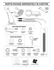
PARTS PACKED SEPARATELY IN CARTON (1) MULTIWRENCH (180684) (1) POWER CORD (198563) (1) SAFTEY IGNITION KEY (35062) (1) AUGER CONTROL ROD (1) TRACTION DRIVE CONTROL ROD (1) DISCHARGE CHUTE EXTRA SHEAR BOLTS ...
PARTS PACKED SEPARATELY IN CARTON (1) MULTIWRENCH (180684) (1) POWER CORD (198563) (1) SAFTEY IGNITION KEY (35062) (1) AUGER CONTROL ROD (1) TRACTION DRIVE CONTROL ROD (1) DISCHARGE CHUTE EXTRA SHEAR BOLTS ...
User Manual
Page 5
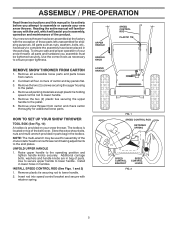
...The toolbox is provided on top of your snow thrower. Use to secure upper handle to complete the assembly have been placed in the parts bag. Remove plastic tie securing rod to ensure proper tightness. Use the correct tools as nuts, washers, bolts, etc., necessary to lower... the skid plates. To ensure safe and proper operation of the belt cover. Remove snow thrower from carton. 2. Cut down all accessible loose parts and parts boxes from carton and check carton thoroughly for shipping purposes. INSTALL SPEED CONTROL ROD (See Figs. 1 and 2) 1. LOWER HANDLE FIG. 1...
...The toolbox is provided on top of your snow thrower. Use to secure upper handle to complete the assembly have been placed in the parts bag. Remove plastic tie securing rod to ensure proper tightness. Use the correct tools as nuts, washers, bolts, etc., necessary to lower... the skid plates. To ensure safe and proper operation of the belt cover. Remove snow thrower from carton. 2. Cut down all accessible loose parts and parts boxes from carton and check carton thoroughly for shipping purposes. INSTALL SPEED CONTROL ROD (See Figs. 1 and 2) 1. LOWER HANDLE FIG. 1...
User Manual
Page 7
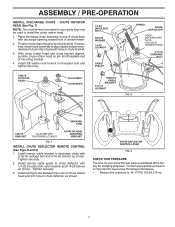
... and 5/16-18 locknut as shown. Position chute rotator head over chute bracket. If necessary, rotate chute assembly to align square and pin on your parts bag may be used to install the chute rotator head. 1. Install spring hooks between hex nuts on threaded stud and tighten securely. 1/4-20 SHOULDER BOLT...
... and 5/16-18 locknut as shown. Position chute rotator head over chute bracket. If necessary, rotate chute assembly to align square and pin on your parts bag may be used to install the chute rotator head. 1. Install spring hooks between hex nuts on threaded stud and tighten securely. 1/4-20 SHOULDER BOLT...
User Manual
Page 10
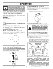
.... 11 TO USE THROTTLE CONTROL (See Fig. 12) The throttle control is located on the engine. Keep the area of operation clear of all moving parts to prevent unauthorized use to "STOP" position. 2. If the discharge chute or auger become clogged, shut-off engine and wait for all persons, small ...fuel tank on the engine. Do not use . OFF FULL FIG. 13 TO CONTROL SNOW DISCHARGE (See Fig. 14) WARNING: Snow throwers have exposed rotating parts, which can result in foreign objects thrown into the eyes, which can result in severe eye damage. Use the clean-out tool, NOT YOUR HANDS...
.... 11 TO USE THROTTLE CONTROL (See Fig. 12) The throttle control is located on the engine. Keep the area of operation clear of all moving parts to prevent unauthorized use to "STOP" position. 2. If the discharge chute or auger become clogged, shut-off engine and wait for all persons, small ...fuel tank on the engine. Do not use . OFF FULL FIG. 13 TO CONTROL SNOW DISCHARGE (See Fig. 14) WARNING: Snow throwers have exposed rotating parts, which can result in foreign objects thrown into the eyes, which can result in severe eye damage. Use the clean-out tool, NOT YOUR HANDS...
User Manual
Page 11
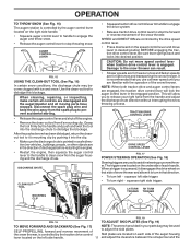
...the clip. • Make sure the discharge chute is pointed in a safe direction (no vehicles, buildings, people, or other objects are in your parts bag may become clogged with the operation of to dislodge this blockage. CAUTION: Do not move lever to prevent accidental starting. • Release the auger... snow thrower can result. • Slower speeds are for heavier snow and faster speeds are disengaged and the auger/impeller and all moving parts have stopped. The triggers are controlled by the handle and push and twist the tool into desired position. LH TURN RH TURN TRIGGER TRIGGER...
...the clip. • Make sure the discharge chute is pointed in a safe direction (no vehicles, buildings, people, or other objects are in your parts bag may become clogged with the operation of to dislodge this blockage. CAUTION: Do not move lever to prevent accidental starting. • Release the auger... snow thrower can result. • Slower speeds are for heavier snow and faster speeds are disengaged and the auger/impeller and all moving parts have stopped. The triggers are controlled by the handle and push and twist the tool into desired position. LH TURN RH TURN TRIGGER TRIGGER...

User Manual
Page 12
... Fig. 20) Use the drift cutters to cut through deep snowdrifts that can be picked up and thrown by loosening the hex nuts, then moving parts to assure fuel freshness. BEFORE STARTING THE ENGINE CHECK ENGINE OIL LEVEL (See Fig. 21) The engine on dipstick is reversible. Repeat for current surface...
... Fig. 20) Use the drift cutters to cut through deep snowdrifts that can be picked up and thrown by loosening the hex nuts, then moving parts to assure fuel freshness. BEFORE STARTING THE ENGINE CHECK ENGINE OIL LEVEL (See Fig. 21) The engine on dipstick is reversible. Repeat for current surface...
User Manual
Page 13
... starter has frozen and will not turn the key. Insert safety ignition key (packed separately in "FAST" position. 3. Place throttle control in parts bag) into ignition slot until it clicks. COLD START - DO NOT turn the engine, proceed as follows: 1. Place throttle control in this...so it clicks. three-wire grounded system. Insert safety ignition key (packed separately in a safe place. 2. Keep the extra safety ignition key in parts bag) into a three-hole grounded 120 Volt A.C. Push the primer four (4) times if the temperature is below 15°F, or two (2) ...
... starter has frozen and will not turn the key. Insert safety ignition key (packed separately in "FAST" position. 3. Place throttle control in parts bag) into ignition slot until it clicks. COLD START - DO NOT turn the engine, proceed as follows: 1. Place throttle control in this...so it clicks. three-wire grounded system. Insert safety ignition key (packed separately in a safe place. 2. Keep the extra safety ignition key in parts bag) into a three-hole grounded 120 Volt A.C. Push the primer four (4) times if the temperature is below 15°F, or two (2) ...
User Manual
Page 14
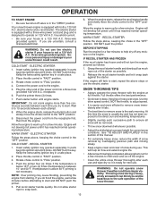
...should replace the spark plug and check belts for wear. Check V-belts for loose fasteners. 3. NOTE: Use only Original Equipment Manufacturer (OEM) parts to service this manual should be checked at least once each season. • Once a year, you should be replaced by original equipment ... SAE 5W-30 Motor Oil See "ENGINE" in both tires (14-17 P.S.I. / 19-24.5 N-m). The belts are functioning properly. Using other parts dealer. Some adjustments will help your nearest dealer. BEFORE EACH USE 1. hours of injury to slip from your engine run better and last longer....
...should replace the spark plug and check belts for wear. Check V-belts for loose fasteners. 3. NOTE: Use only Original Equipment Manufacturer (OEM) parts to service this manual should be checked at least once each season. • Once a year, you should be replaced by original equipment ... SAE 5W-30 Motor Oil See "ENGINE" in both tires (14-17 P.S.I. / 19-24.5 N-m). The belts are functioning properly. Using other parts dealer. Some adjustments will help your nearest dealer. BEFORE EACH USE 1. hours of injury to slip from your engine run better and last longer....
User Manual
Page 16
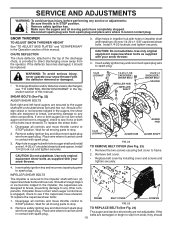
.../shear bolts as supplied with hole in the impeller, the capscrews are designed to break, preventing damage to stop . 2. Disengage all moving parts have sheared. Remove the two screws securing belt cover to spark plug. Remove belt cover. • Replace belt cover by installing cover and... and tighten securely. 4. IMPELLER SHEAR BOLTS The impeller is in the Operation section of this manual. Make sure the augers and all moving parts to any service or adjustments: 1. Insert safety ignition key and reconnect spark plug wire to frame. 2. Align hole in auger hub with...
.../shear bolts as supplied with hole in the impeller, the capscrews are designed to break, preventing damage to stop . 2. Disengage all moving parts have sheared. Remove the two screws securing belt cover to spark plug. Remove belt cover. • Replace belt cover by installing cover and... and tighten securely. 4. IMPELLER SHEAR BOLTS The impeller is in the Operation section of this manual. Make sure the augers and all moving parts to any service or adjustments: 1. Insert safety ignition key and reconnect spark plug wire to frame. 2. Align hole in auger hub with...
User Manual
Page 17
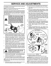
... and inside belt keepers. 17 dealer. If auger belt has become dislodged from crankshaft. 5. HANDLES 1. REMOVE GASOLINE FROM FUEL TANK - Wipe up on your local parts belt around and inside belt keeper. 16. REMOVE BELT COVER - Remove outside (auger) pulley only from the pulley (by catching the idler arm bracket while...
... and inside belt keepers. 17 dealer. If auger belt has become dislodged from crankshaft. 5. HANDLES 1. REMOVE GASOLINE FROM FUEL TANK - Wipe up on your local parts belt around and inside belt keeper. 16. REMOVE BELT COVER - Remove outside (auger) pulley only from the pulley (by catching the idler arm bracket while...
User Manual
Page 18
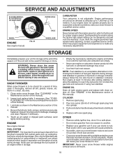
...season. Be sure that does not retain moisture. FUEL SYSTEM IMPORTANT: It is factory set for a period of an engine while in essential fuel system parts such as on stabilizer container. Acidic gas can starts to prevent gum deposits from forming in storage. • Empty the fuel tank by starting the.... Always follow the mix ratio found on a furnace, water heater, clothes dryer or gas appliance. CYLINDER 1. Pour one season to distribute oil. 4. Inspect moving parts for 30 days or more. Replace if necessary. 5. Lubricate as shown in a clean, dry area. 1.
...season. Be sure that does not retain moisture. FUEL SYSTEM IMPORTANT: It is factory set for a period of an engine while in essential fuel system parts such as on stabilizer container. Acidic gas can starts to prevent gum deposits from forming in storage. • Empty the fuel tank by starting the.... Always follow the mix ratio found on a furnace, water heater, clothes dryer or gas appliance. CYLINDER 1. Pour one season to distribute oil. 4. Inspect moving parts for 30 days or more. Replace if necessary. 5. Lubricate as shown in a clean, dry area. 1.
User Manual
Page 19
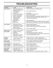
... fresh, clean fuel. 4. Reduce speed and width of traction 1. Clean or replace muffler. Move choke to FULL position. 6. Loose parts or damaged augers or impeller. 1. If vibration remains, contact a qualified service centre. Remove debris or foreign object from augers / impeller...spark plug. 10. Drain tank and refill with fresh gasoline. Drain fuel tank and carburetor, refill tank with fresh gasoline. 11. Replace damaged parts. Loss of swath. 3. Check / reinstall drive belt. Friction drive wheel is off of adjustment or overhaul. 1. Auger belt is flooded. ...
... fresh, clean fuel. 4. Reduce speed and width of traction 1. Clean or replace muffler. Move choke to FULL position. 6. Loose parts or damaged augers or impeller. 1. If vibration remains, contact a qualified service centre. Remove debris or foreign object from augers / impeller...spark plug. 10. Drain tank and refill with fresh gasoline. Drain fuel tank and carburetor, refill tank with fresh gasoline. 11. Replace damaged parts. Loss of swath. 3. Check / reinstall drive belt. Friction drive wheel is off of adjustment or overhaul. 1. Auger belt is flooded. ...
User Manual
Page 21
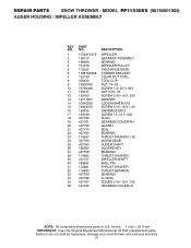
... THROWER - inches. 1 inch = 25.4 mm IMPORTANT: Use only Original Equipment Manufacturer (O.E.M.) replacement parts. Failure to do so could be hazardous, damage your snow thrower and void your warranty. 21 MODEL PP11530ES (96192001902) AUGER HOUSING / IMPELLER ASSEMBLY KEY NO. 1 2 3 4 5 6 7 8 9 10 11 12 13 14 15 16 17 18 19 20 ...21 22 23 24 25 26 27 28 29 30 31 32 33 34 35 36 PART NO. 175321X479 196710 188909 191079 175322 ...
... THROWER - inches. 1 inch = 25.4 mm IMPORTANT: Use only Original Equipment Manufacturer (O.E.M.) replacement parts. Failure to do so could be hazardous, damage your snow thrower and void your warranty. 21 MODEL PP11530ES (96192001902) AUGER HOUSING / IMPELLER ASSEMBLY KEY NO. 1 2 3 4 5 6 7 8 9 10 11 12 13 14 15 16 17 18 19 20 ...21 22 23 24 25 26 27 28 29 30 31 32 33 34 35 36 PART NO. 175321X479 196710 188909 191079 175322 ...
User Manual
Page 22
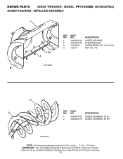
MODEL PP11530ES (96192001902) AUGER HOUSING / IMPELLER ASSEMBLY 1 3 (5x) 4 (5x) 2 01.07.003-A KEY NO. 1 2 3 4 PART NO. 404930X428 404933X479 72270505 155377 DESCRIPTION AUGER HOUSING SCRAPPER BAR CARRIAGE BOLT 5/16−18 X .625 NUT 5/16−18 2 1 KEY NO. 1 2 PART NO. 420497X479 420498X479 DESCRIPTION AUGER ASSEMBLY 30 LH AUGER ASSEMBLY 30 RH 01.07.019-A NOTE...
MODEL PP11530ES (96192001902) AUGER HOUSING / IMPELLER ASSEMBLY 1 3 (5x) 4 (5x) 2 01.07.003-A KEY NO. 1 2 3 4 PART NO. 404930X428 404933X479 72270505 155377 DESCRIPTION AUGER HOUSING SCRAPPER BAR CARRIAGE BOLT 5/16−18 X .625 NUT 5/16−18 2 1 KEY NO. 1 2 PART NO. 420497X479 420498X479 DESCRIPTION AUGER ASSEMBLY 30 LH AUGER ASSEMBLY 30 RH 01.07.019-A NOTE...
User Manual
Page 23
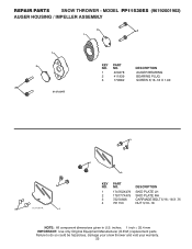
MODEL PP11530ES (96192001902) AUGER HOUSING / IMPELLER ASSEMBLY 2 3 1 1 2 3 01.07.024-B KEY NO. 1 2 3 PART NO. 420478 411939 179582 DESCRIPTION AUGER BEARING BEARING PLUG SCREW 5/16−18 X 1.00 3 4 3 01.11.001-A 1 4 2 KEY NO. 1 2 3 4 PART NO. 174762X479 178777X479 72270506 751153 DESCRIPTION SKID PLATE LH SKID PLATE RH CARRIAGE BOLT 5/16−18 X .75 NUT 5/16...so could be hazardous, damage your snow thrower and void your warranty. 23 inches. 1 inch = 25.4 mm IMPORTANT: Use only Original Equipment Manufacturer (O.E.M.) replacement parts. REPAIR PARTS SNOW THROWER -
MODEL PP11530ES (96192001902) AUGER HOUSING / IMPELLER ASSEMBLY 2 3 1 1 2 3 01.07.024-B KEY NO. 1 2 3 PART NO. 420478 411939 179582 DESCRIPTION AUGER BEARING BEARING PLUG SCREW 5/16−18 X 1.00 3 4 3 01.11.001-A 1 4 2 KEY NO. 1 2 3 4 PART NO. 174762X479 178777X479 72270506 751153 DESCRIPTION SKID PLATE LH SKID PLATE RH CARRIAGE BOLT 5/16−18 X .75 NUT 5/16...so could be hazardous, damage your snow thrower and void your warranty. 23 inches. 1 inch = 25.4 mm IMPORTANT: Use only Original Equipment Manufacturer (O.E.M.) replacement parts. REPAIR PARTS SNOW THROWER -
User Manual
Page 24
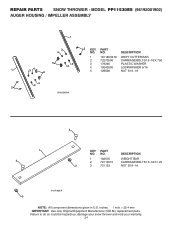
... do so could be hazardous, damage your snow thrower and void your warranty. 24 MODEL PP11530ES (96192001902) AUGER HOUSING / IMPELLER ASSEMBLY 1 3 2 KEY PART 4 NO. REPAIR PARTS SNOW THROWER - inches. 1 inch = 25.4 mm IMPORTANT: Use only Original Equipment Manufacturer (O.E.M.) replacement parts. NO. DESCRIPTION 1 182516 WEIGHT BAR 2 72110510 CARRIAGE BOLT 5/16−18 X 1.25 3 3 751153 NUT...
... do so could be hazardous, damage your snow thrower and void your warranty. 24 MODEL PP11530ES (96192001902) AUGER HOUSING / IMPELLER ASSEMBLY 1 3 2 KEY PART 4 NO. REPAIR PARTS SNOW THROWER - inches. 1 inch = 25.4 mm IMPORTANT: Use only Original Equipment Manufacturer (O.E.M.) replacement parts. NO. DESCRIPTION 1 182516 WEIGHT BAR 2 72110510 CARRIAGE BOLT 5/16−18 X 1.25 3 3 751153 NUT...
User Manual
Page 25
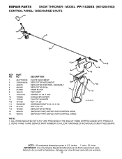
...inches. 1 inch = 25.4 mm IMPORTANT: Use only Original Equipment Manufacturer (O.E.M.) replacement parts. NOTE: All component dimensions given in U.S. Failure to do so could be hazardous, damage your snow thrower and void your warranty. 25 MODEL PP11530ES (96192001902) CONTROL PANEL / DISCHARGE CHUTE 5 7 14 3 15 *13 KEY NO.... 1 2 3 4 5 6 7 *8 *9 *10 *11 *12 *13 14 15 PART NO. 404770X428 178633X428 420673 420325 414280 128415 17501010 179829 179246 ...
...inches. 1 inch = 25.4 mm IMPORTANT: Use only Original Equipment Manufacturer (O.E.M.) replacement parts. NOTE: All component dimensions given in U.S. Failure to do so could be hazardous, damage your snow thrower and void your warranty. 25 MODEL PP11530ES (96192001902) CONTROL PANEL / DISCHARGE CHUTE 5 7 14 3 15 *13 KEY NO.... 1 2 3 4 5 6 7 *8 *9 *10 *11 *12 *13 14 15 PART NO. 404770X428 178633X428 420673 420325 414280 128415 17501010 179829 179246 ...
User Manual
Page 26
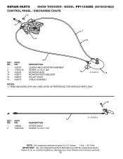
...CABLE 2 74041024 SCREW 10−24 X 1.50 01.15.005-A NOTE: All component dimensions given in U.S. MODEL PP11530ES (96192001902) CONTROL PANEL / DISCHARGE CHUTE 2 2 *3 1 *6 KEY NO. 1 2 *3 *4 *5 *6 PART NO. 420337 17501010 420678 420677 420675 420674 *6 DESCRIPTION LEVER/CABLE ROTATOR ASSEMBLY SCREW 10−24 X .625 ROTATOR HEAD... PIVOT CABLE ASSEMBLY *4 01.09.007-A *5 NOTES: 1. ITEMS INDICATED WITH AN * ARE LISTED AS REFERENCE FOR SERVICE PARTS ONLY. 2 1 KEY PART NO. Failure to do so could be hazardous, damage your snow thrower and void your warranty. 26 NO. REPAIR...
...CABLE 2 74041024 SCREW 10−24 X 1.50 01.15.005-A NOTE: All component dimensions given in U.S. MODEL PP11530ES (96192001902) CONTROL PANEL / DISCHARGE CHUTE 2 2 *3 1 *6 KEY NO. 1 2 *3 *4 *5 *6 PART NO. 420337 17501010 420678 420677 420675 420674 *6 DESCRIPTION LEVER/CABLE ROTATOR ASSEMBLY SCREW 10−24 X .625 ROTATOR HEAD... PIVOT CABLE ASSEMBLY *4 01.09.007-A *5 NOTES: 1. ITEMS INDICATED WITH AN * ARE LISTED AS REFERENCE FOR SERVICE PARTS ONLY. 2 1 KEY PART NO. Failure to do so could be hazardous, damage your snow thrower and void your warranty. 26 NO. REPAIR...


