

User Manual
Page 2
... to a running (except when specifically recommended by the manufacturer for Walk-Behind Snow Throwers This snow thrower is capable of all times, until refueling is highly flammable (f) Keep the nozzle in order to operate the equipment without wearing adequate winter garments. WARNING: Always disconnect spark plug wire and place it where it is complete. Never allow adults to prevent accidental starting the engine (motor). 3. Keep...
... to a running (except when specifically recommended by the manufacturer for Walk-Behind Snow Throwers This snow thrower is capable of all times, until refueling is highly flammable (f) Keep the nozzle in order to operate the equipment without wearing adequate winter garments. WARNING: Always disconnect spark plug wire and place it where it is complete. Never allow adults to prevent accidental starting the engine (motor). 3. Keep...
User Manual
Page 3
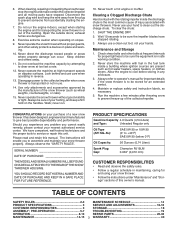
... any enclosure. 3. We have stopped. SERIAL NUMBER DATE OF PURCHASE THE MODEL AND SERIAL NUMBERS WILL BE FOUND ON A DECAL ATTACHED TO THE REAR OF THE SNOW THROWER HOUSING. TABLE OF CONTENTS SAFETY RULES 2-3 MAINTENANCE SCHEDULE 14 PRODUCT SPECIFICATIONS 3 SERVICE AND ADJUSTMENTS 16-18 CUSTOMER RESPONSIBILITIES 3 STORAGE 18 ASSEMBLY / PRE-OPERATION 5-7 TROUBLESHOOTING 19 OPERATION 8-13 REPAIR PARTS 20-38 MAINTENANCE 14-15 3 WARRANTY 40 6. Disconnect the spark plug wire and keep a firm hold on...
... any enclosure. 3. We have stopped. SERIAL NUMBER DATE OF PURCHASE THE MODEL AND SERIAL NUMBERS WILL BE FOUND ON A DECAL ATTACHED TO THE REAR OF THE SNOW THROWER HOUSING. TABLE OF CONTENTS SAFETY RULES 2-3 MAINTENANCE SCHEDULE 14 PRODUCT SPECIFICATIONS 3 SERVICE AND ADJUSTMENTS 16-18 CUSTOMER RESPONSIBILITIES 3 STORAGE 18 ASSEMBLY / PRE-OPERATION 5-7 TROUBLESHOOTING 19 OPERATION 8-13 REPAIR PARTS 20-38 MAINTENANCE 14-15 3 WARRANTY 40 6. Disconnect the spark plug wire and keep a firm hold on...
User Manual
Page 5
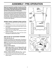
... adjustments to lower handle. Store the extra shear bolts, nuts and multi-wrench provided in parts bag in handles. Raise upper handle to the pallet. 4. Insert rod into speed control bracket and secure with the exception of the product. Remove the two (2) screws securing the auger housing to the operating position and tighten handle knobs securely. Remove snow thrower from carton. 2. Remove plastic tie securing rod to the pallet. 6. Your new snow thrower has been assembled...
... adjustments to lower handle. Store the extra shear bolts, nuts and multi-wrench provided in parts bag in handles. Raise upper handle to the pallet. 4. Insert rod into speed control bracket and secure with the exception of the product. Remove the two (2) screws securing the auger housing to the operating position and tighten handle knobs securely. Remove snow thrower from carton. 2. Remove plastic tie securing rod to the pallet. 6. Your new snow thrower has been assembled...
User Manual
Page 7
... parts bag may be used to 14-17 PSI (19-24.5 N-m). 7 CHUTE DEFLECTOR CONTROL LEVER FIG. 9 CHECK TIRE PRESSURE The tires on pin and threaded stud of snow thrower. 2. Install 3/8 washer and locknut on chute rotater head and into hole in your snow thrower were overinflated at the factory for best snow throwing performance. • Reduce tire pressure to install the chute rotator head. 1. Position chute rotator head over chute bracket. Install spring hooks between hex nuts...
... parts bag may be used to 14-17 PSI (19-24.5 N-m). 7 CHUTE DEFLECTOR CONTROL LEVER FIG. 9 CHECK TIRE PRESSURE The tires on pin and threaded stud of snow thrower. 2. Install 3/8 washer and locknut on chute rotater head and into hole in your snow thrower were overinflated at the factory for best snow throwing performance. • Reduce tire pressure to install the chute rotator head. 1. Position chute rotator head over chute bracket. Install spring hooks between hex nuts...
User Manual
Page 8
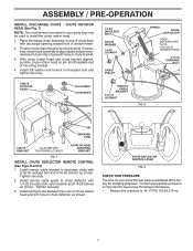
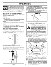
... AND INSTRUCTIONS BEFORE USE OF THIS PRODUCT. INSERT TO START AND RUN, PULL OUT TO STOP. KEEP THESE INSTRUCTIONS FOR FUTURE REFERENCE. IGNITION KEY. Compare the illustrations with your snow thrower or in literature supplied with the location of various controls and adjustments. DISENGAGED ENGAGED SNOW DISCHARGE TRACTION DRIVE CONTROL 8 Save this manual for future reference. OPERATION KNOW YOUR SNOW THROWER READ THIS OWNER'S MANUAL AND ALL SAFETY RULES BEFORE OPERATING YOUR SNOW THROWER.
... AND INSTRUCTIONS BEFORE USE OF THIS PRODUCT. INSERT TO START AND RUN, PULL OUT TO STOP. KEEP THESE INSTRUCTIONS FOR FUTURE REFERENCE. IGNITION KEY. Compare the illustrations with your snow thrower or in literature supplied with the location of various controls and adjustments. DISENGAGED ENGAGED SNOW DISCHARGE TRACTION DRIVE CONTROL 8 Save this manual for future reference. OPERATION KNOW YOUR SNOW THROWER READ THIS OWNER'S MANUAL AND ALL SAFETY RULES BEFORE OPERATING YOUR SNOW THROWER.
User Manual
Page 9
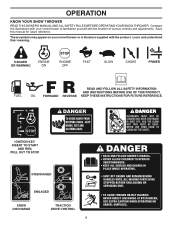
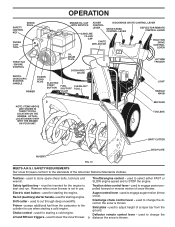
... FILLER CAP CHUTE DEFLECTOR TRACTION DRIVE CONTROL LEVER THROTTLE / ENGINE CONTROL OIL DRAIN PLUG DISCHARGE CHUTE RECOIL (AUXILIARY) STARTER HANDLE PRIMER POWER CORD PLUG ELECTRIC START BUTTON FUEL SHUT-OFF VALVE CLEAN-OUT TOOL LH TURN TRIGGER LIGHT HANDLE KNOB NOTE: ITEMS ABOVE ARE SHOWN IN THEIR TYPICAL LOCATION ON THE ENGINE. MUFFLER TOOLBOX DRIFT CUTTER SKID PLATE AUGERS FIG. 10 MEETS A.N.S.I. Toolbox - used to change the direction the snow is not in use when starting the engine. Throttle/engine control - Electric start and run. Deflector remote control lever...
... FILLER CAP CHUTE DEFLECTOR TRACTION DRIVE CONTROL LEVER THROTTLE / ENGINE CONTROL OIL DRAIN PLUG DISCHARGE CHUTE RECOIL (AUXILIARY) STARTER HANDLE PRIMER POWER CORD PLUG ELECTRIC START BUTTON FUEL SHUT-OFF VALVE CLEAN-OUT TOOL LH TURN TRIGGER LIGHT HANDLE KNOB NOTE: ITEMS ABOVE ARE SHOWN IN THEIR TYPICAL LOCATION ON THE ENGINE. MUFFLER TOOLBOX DRIFT CUTTER SKID PLATE AUGERS FIG. 10 MEETS A.N.S.I. Toolbox - used to change the direction the snow is not in use when starting the engine. Throttle/engine control - Electric start and run. Deflector remote control lever...
User Manual
Page 10
... auger control lever to operate all times including startup. Remove (do not turn) safety ignition key to prevent unauthorized use to start a warm engine. • To engage choke, turn knob counterclockwise to "STOP" position. 2. Always operate the snow thrower with the engine at all controls before adding fuel or attempting to start the engine. Use the choke control whenever you are starting a cold engine. Keep the area of operation clear of all persons, small children and pets at full throttle...
... auger control lever to operate all times including startup. Remove (do not turn) safety ignition key to prevent unauthorized use to start a warm engine. • To engage choke, turn knob counterclockwise to "STOP" position. 2. Always operate the snow thrower with the engine at all controls before adding fuel or attempting to start the engine. Use the choke control whenever you are starting a cold engine. Keep the area of operation clear of all persons, small children and pets at full throttle...
User Manual
Page 11
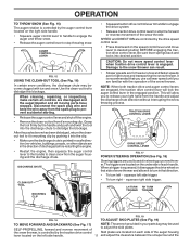
Use the clean-out tool to prevent accidental starting. • Release the auger control lever and shut off the engine. • Remove the clean-out tool from the spark plug to dislodge this blockage. Disconnect the spark plug wire and keep the wire away from it disengages the drive wheel on that you use a slower speed until you to dislodge the blockage. SPEED and DIRECTION are for light snow and transporting the snow thrower. Damage to...
Use the clean-out tool to prevent accidental starting. • Release the auger control lever and shut off the engine. • Remove the clean-out tool from the spark plug to dislodge this blockage. Disconnect the spark plug wire and keep the wire away from it disengages the drive wheel on that you use a slower speed until you to dislodge the blockage. SPEED and DIRECTION are for light snow and transporting the snow thrower. Damage to...

User Manual
Page 12
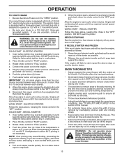
... to lowest (highest scraper clearance) position. 1. If necessary, add oil until the fuel lines and carburetor are adjusted to the snow thrower. • If snow thrower must be emptied before requiring replacement. CHOKE CONTROL THROTTLE PRIMER ENGINE OIL FILL CAP / DIPSTICK SAFETY IGNITION KEY AUGER HOUSING STORAGE POSITION FIG. 20 DRIFT CUTTER ADJUSTMENT NUT GASOLINE FILLER CAP RECOIL STARTER HANDLE FUEL SHUTOFF VALVE STARTER BUTTON POWER CORD PLUG NOTE: ALL ITEMS ARE SHOWN IN THEIR TYPICAL LOCATION. For removal of snow in normal conditions, such as...
... to lowest (highest scraper clearance) position. 1. If necessary, add oil until the fuel lines and carburetor are adjusted to the snow thrower. • If snow thrower must be emptied before requiring replacement. CHOKE CONTROL THROTTLE PRIMER ENGINE OIL FILL CAP / DIPSTICK SAFETY IGNITION KEY AUGER HOUSING STORAGE POSITION FIG. 20 DRIFT CUTTER ADJUSTMENT NUT GASOLINE FILLER CAP RECOIL STARTER HANDLE FUEL SHUTOFF VALVE STARTER BUTTON POWER CORD PLUG NOTE: ALL ITEMS ARE SHOWN IN THEIR TYPICAL LOCATION. For removal of snow in normal conditions, such as...
User Manual
Page 13
...: Do not use . ELECTRIC STARTER 1. DO NOT push the primer. three-wire grounded system. Pull recoil starter handle quickly. COLD START - Disconnect the power cord from the receptacle first, then from starting. NOTE: Over priming may cause flooding, preventing the engine from the engine. Full throttle offers the best performance. • Go slower in the "OPEN" position. OPERATION TO START ENGINE • Be sure fuel shut-off valve is in deep...
...: Do not use . ELECTRIC STARTER 1. DO NOT push the primer. three-wire grounded system. Pull recoil starter handle quickly. COLD START - Disconnect the power cord from the receptacle first, then from starting. NOTE: Over priming may cause flooding, preventing the engine from the engine. Full throttle offers the best performance. • Go slower in the "OPEN" position. OPERATION TO START ENGINE • Be sure fuel shut-off valve is in deep...
User Manual
Page 14
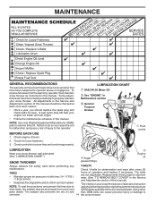
... adjustments will help your engine run better and last longer. • Follow the maintenance schedule in Maintenance section General Purpose Grease Pivot points LUBRICATION Keep your snow thrower. Check V-belts for deterioration and wear after every 50 TIRES • Maintain proper air pressure in this manual. Check engine oil level. 2. To receive full value from the warranty, operator must maintain snow thrower as instructed in both tires (14-17 P.S.I. / 19-24.5 N-m). A new spark plug will need...
... adjustments will help your engine run better and last longer. • Follow the maintenance schedule in Maintenance section General Purpose Grease Pivot points LUBRICATION Keep your snow thrower. Check V-belts for deterioration and wear after every 50 TIRES • Maintain proper air pressure in this manual. Check engine oil level. 2. To receive full value from the warranty, operator must maintain snow thrower as instructed in both tires (14-17 P.S.I. / 19-24.5 N-m). A new spark plug will need...
User Manual
Page 15
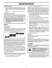
... the snow thrower is required, use . Select the oil's SAE viscosity grade according to install klick pin into proper hole in wheel axle (See "TO REMOVE WHEELS" in the Service and Adjustments section of your expected operating temperature. Check the crankcase oil level before next oil change. Be sure to your snow thrower. Wipe off any oil trapped inside the snow thrower. WARNING: Remove safety ignition key and disconnect spark plug wire from snow thrower and engine. 6. The sprockets, hex shafts, drive...
... the snow thrower is required, use . Select the oil's SAE viscosity grade according to install klick pin into proper hole in wheel axle (See "TO REMOVE WHEELS" in the Service and Adjustments section of your expected operating temperature. Check the crankcase oil level before next oil change. Be sure to your snow thrower. Wipe off any oil trapped inside the snow thrower. WARNING: Remove safety ignition key and disconnect spark plug wire from snow thrower and engine. 6. The sprockets, hex shafts, drive...
User Manual
Page 16
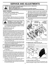
... sure throttle is engaged, check to stop . 2. WARNING: To avoid serious injury, never operate your snow thrower. 1/4-20 LOCKNUT 1/4-20 x 1-5/8 CAPSCREW / SHEAR BOLT IMPELLER HUB IMPELLER SHAFT 1/4-20 x 2 SHOULDER / SHEAR BOLT SPACER AUGER HUB 1/4-20 LOCKNUT AUGER HUB AUGER SHAFT FIG. 22 TO REMOVE BELT COVER (See Fig. 23) 1. Install 1/4-20 lock nut and tighten securely. If impeller does not turn when auger control lever is in contact with spark plug. 3. FRAME BELT COVER FIG. 23 SCREWS 2. Place wire where...
... sure throttle is engaged, check to stop . 2. WARNING: To avoid serious injury, never operate your snow thrower. 1/4-20 LOCKNUT 1/4-20 x 1-5/8 CAPSCREW / SHEAR BOLT IMPELLER HUB IMPELLER SHAFT 1/4-20 x 2 SHOULDER / SHEAR BOLT SPACER AUGER HUB 1/4-20 LOCKNUT AUGER HUB AUGER SHAFT FIG. 22 TO REMOVE BELT COVER (See Fig. 23) 1. Install 1/4-20 lock nut and tighten securely. If impeller does not turn when auger control lever is in contact with spark plug. 3. FRAME BELT COVER FIG. 23 SCREWS 2. Place wire where...
User Manual
Page 17
... allow chute rotator head to be replaced at the same time. REMOVE BELT COVER - to the snow thrower. Tire sealant also prevents tire dry rot and corrosion. The V-belts on crankshaft. FRAME ASSEMBLY AUGER HOUSING 10. Belt must be sure to use the hole HINT: Insert a 3/8" drive ratchet (in groove of auger pulley only. 12. Drain gasoline from your snow thrower are not used for proper routing of this manual. 4. IMPORTANT: When installing wheel, be...
... allow chute rotator head to be replaced at the same time. REMOVE BELT COVER - to the snow thrower. Tire sealant also prevents tire dry rot and corrosion. The V-belts on crankshaft. FRAME ASSEMBLY AUGER HOUSING 10. Belt must be sure to use the hole HINT: Insert a 3/8" drive ratchet (in groove of auger pulley only. 12. Drain gasoline from your snow thrower are not used for proper routing of this manual. 4. IMPORTANT: When installing wheel, be...
User Manual
Page 18
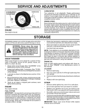
.... ENGINE See engine manual. Run engine at altitudes up all dirt, grease, leaves, etc. ENGINE OIL Drain oil (with engine warm) and replace with new spark plug. Pour one season to protect it from dust and dirt. • Cover your can damage the fuel system of this manual). 2. Pull recoil starter handle slowly a few times to gasoline in essential fuel system parts such as carburetor, fuel hose, or tank during storage. Rust and/or dirt in the Maintenance...
.... ENGINE See engine manual. Run engine at altitudes up all dirt, grease, leaves, etc. ENGINE OIL Drain oil (with engine warm) and replace with new spark plug. Pour one season to protect it from dust and dirt. • Cover your can damage the fuel system of this manual). 2. Pull recoil starter handle slowly a few times to gasoline in essential fuel system parts such as carburetor, fuel hose, or tank during storage. Rust and/or dirt in the Maintenance...
User Manual
Page 19
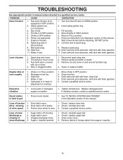
Safety ignition key is covered with ice or snow. 4. Throttle in fuel line. 3. Stale fuel. 11. Connect wire to OFF position. 2. Drain fuel tank and carburetor, refill tank with fresh gasoline. 11. Fuel tank cap is not inserted. 3. Reconnect spark plug wire. 2. Engine idles or runs roughly 1. Stale fuel. 4. Replace damaged parts. Loss of pulley. 2. drive / slowing 2. Check / reinstall drive belt. Auger belt is off of traction 1. Check / replace auger belt. 3. Remove debris or foreign object from augers / impeller. 19 Turn fuel shut-off valve (if so ...
Safety ignition key is covered with ice or snow. 4. Throttle in fuel line. 3. Stale fuel. 11. Connect wire to OFF position. 2. Drain fuel tank and carburetor, refill tank with fresh gasoline. 11. Fuel tank cap is not inserted. 3. Reconnect spark plug wire. 2. Engine idles or runs roughly 1. Stale fuel. 4. Replace damaged parts. Loss of pulley. 2. drive / slowing 2. Check / reinstall drive belt. Auger belt is off of traction 1. Check / replace auger belt. 3. Remove debris or foreign object from augers / impeller. 19 Turn fuel shut-off valve (if so ...
User Manual
Page 21
... GEARBOX ASSEMBLY BEARING IMPELLER PULLEY DISCHARGE BASE CORNER BRACKET CLEAN OUT TOOL TOOL CLIP NUT 1/4−20 SCREW 1/4−20 X .625 NUT 5/16−18 SCREW 5/16−18 X .625 WASHER LOCKWASHER 5/16 SCREW 5/16−18 X 1.00 CARRIAGE BOLT SCREW 13−16 X .625 PLUG GEARBOX COVER RH GASKET SEAL BEARING THRUST WASHER 1.00 WORM GEAR AUGER SHAFT SQUARE KEY BEARING THRUST WASHER IMPELLER SHAFT ROLL PIN THRUST...
... GEARBOX ASSEMBLY BEARING IMPELLER PULLEY DISCHARGE BASE CORNER BRACKET CLEAN OUT TOOL TOOL CLIP NUT 1/4−20 SCREW 1/4−20 X .625 NUT 5/16−18 SCREW 5/16−18 X .625 WASHER LOCKWASHER 5/16 SCREW 5/16−18 X 1.00 CARRIAGE BOLT SCREW 13−16 X .625 PLUG GEARBOX COVER RH GASKET SEAL BEARING THRUST WASHER 1.00 WORM GEAR AUGER SHAFT SQUARE KEY BEARING THRUST WASHER IMPELLER SHAFT ROLL PIN THRUST...
User Manual
Page 22
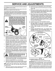
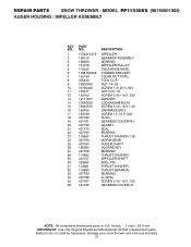
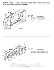
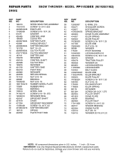
inches. 1 inch = 25.4 mm IMPORTANT: Use only Original Equipment Manufacturer (O.E.M.) replacement parts. REPAIR PARTS SNOW THROWER - MODEL PP11530ES (96192001902) AUGER HOUSING / IMPELLER ASSEMBLY 1 3 (5x) 4 (5x) 2 01.07.003-A KEY NO. 1 2 3 4 PART NO. 404930X428 404933X479 72270505 155377 DESCRIPTION AUGER HOUSING SCRAPPER BAR CARRIAGE BOLT 5/16−18 X .625 NUT 5/16−18 2 1 KEY NO. 1 2 PART NO. 420497X479 420498X479 DESCRIPTION AUGER ASSEMBLY 30 LH AUGER ASSEMBLY 30 RH 01.07.019-A NOTE: All component dimensions given in U.S. Failure...
inches. 1 inch = 25.4 mm IMPORTANT: Use only Original Equipment Manufacturer (O.E.M.) replacement parts. REPAIR PARTS SNOW THROWER - MODEL PP11530ES (96192001902) AUGER HOUSING / IMPELLER ASSEMBLY 1 3 (5x) 4 (5x) 2 01.07.003-A KEY NO. 1 2 3 4 PART NO. 404930X428 404933X479 72270505 155377 DESCRIPTION AUGER HOUSING SCRAPPER BAR CARRIAGE BOLT 5/16−18 X .625 NUT 5/16−18 2 1 KEY NO. 1 2 PART NO. 420497X479 420498X479 DESCRIPTION AUGER ASSEMBLY 30 LH AUGER ASSEMBLY 30 RH 01.07.019-A NOTE: All component dimensions given in U.S. Failure...
User Manual
Page 33
... PULLEY WASHER 3/8 LOCKWASHER 3/8 LOCKWASHER BELT GUIDE IDLER ARM IDLER BRACKET IDLER PULLEY SCREW 5/16−18 X 1.50 NUT 5/16−18 PIN IDLER PIVOT IDLER SPRING RETAINER SCREW 3/8−24 X 1.375 PULLEY SHAFT DRIVE PLATE BEARING PULLEY HALF SCREW 10−24 X .50 SPACER BEARING SWING PLATE NUT 3/8−16 WASHER 20 X 8.5 X 2.0 NOTE: All component dimensions given in U.S. inches. 1 inch = 25.4 mm IMPORTANT: Use only Original Equipment Manufacturer (O.E.M.) replacement parts...
... PULLEY WASHER 3/8 LOCKWASHER 3/8 LOCKWASHER BELT GUIDE IDLER ARM IDLER BRACKET IDLER PULLEY SCREW 5/16−18 X 1.50 NUT 5/16−18 PIN IDLER PIVOT IDLER SPRING RETAINER SCREW 3/8−24 X 1.375 PULLEY SHAFT DRIVE PLATE BEARING PULLEY HALF SCREW 10−24 X .50 SPACER BEARING SWING PLATE NUT 3/8−16 WASHER 20 X 8.5 X 2.0 NOTE: All component dimensions given in U.S. inches. 1 inch = 25.4 mm IMPORTANT: Use only Original Equipment Manufacturer (O.E.M.) replacement parts...
User Manual
Page 40
...engine or components parts thereof. Transportation charges for the movement of any power equipment unit or attachment are belts, shear pins, normal wear, normal adjustments, standard hardware and normal maintenance. 6. Should you have a claim under this Warranty, you have any products used for any unanswered questions concerning this Warranty.... Transportation charges for replacement under this warranty must return the product to materials or workmanship. Exclusions: Excluded from defects in accordance with the instructions furnished. ID#, serial number and date of purchase...
...engine or components parts thereof. Transportation charges for the movement of any power equipment unit or attachment are belts, shear pins, normal wear, normal adjustments, standard hardware and normal maintenance. 6. Should you have a claim under this Warranty, you have any products used for any unanswered questions concerning this Warranty.... Transportation charges for replacement under this warranty must return the product to materials or workmanship. Exclusions: Excluded from defects in accordance with the instructions furnished. ID#, serial number and date of purchase...


