
User Manual
Page 1
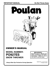
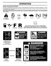
Always Wear Eye Protection During Operation 199248 Rev. 3 07.21.05 BY Printed in serious injury. IMPORTANT MANUAL Do Not Throw Away OWNER'S MANUAL MODEL NUMBER: PO927ES SNOW THROWER WARNING: Read the Owner's Manual and follow all Warnings and Safety Instructions. Failure to do so can result in U.S.A.
Always Wear Eye Protection During Operation 199248 Rev. 3 07.21.05 BY Printed in serious injury. IMPORTANT MANUAL Do Not Throw Away OWNER'S MANUAL MODEL NUMBER: PO927ES SNOW THROWER WARNING: Read the Owner's Manual and follow all Warnings and Safety Instructions. Failure to do so can result in U.S.A.
User Manual
Page 2
... the nozzle in moving parts. WARNING: Snow throwers have exposed rotating parts, which can get caught in contact with the rim of the fuel tank or container opening at all times. (a) Use an approved fuel container. 2. Know how to operate the equipment. Never allow children to stop the engine (motor), remove the wire from the spark plug, disconnect the cord on electric motors, thoroughly inspect the snow (d) Never fill...
... the nozzle in moving parts. WARNING: Snow throwers have exposed rotating parts, which can get caught in contact with the rim of the fuel tank or container opening at all times. (a) Use an approved fuel container. 2. Know how to operate the equipment. Never allow children to stop the engine (motor), remove the wire from the spark plug, disconnect the cord on electric motors, thoroughly inspect the snow (d) Never fill...
User Manual
Page 3
... technicians and the proper tools to clear snow at high transport speeds on slopes. 9. SERIAL NUMBER DATE OF PURCHASE THE MODEL AND SERIAL NUMBERS WILL BE FOUND ON A DECAL ATTACHED TO THE REAR OF THE SNOW THROWER HOUSING. TABLE OF CONTENTS SAFETY RULES 2-3 MAINTENANCE SCHEDULE 14 PRODUCT SPECIFICATIONS 3 SERVICE AND ADJUSTMENTS 16-18 CUSTOMER RESPONSIBILITIES 3 STORAGE 18 ASSEMBLY / PRE-OPERATION 5-7 TROUBLESHOOTING 19 OPERATION 8-13 REPAIR PARTS 20-31 MAINTENANCE 14-15 3 WARRANTY 32 Never direct...
... technicians and the proper tools to clear snow at high transport speeds on slopes. 9. SERIAL NUMBER DATE OF PURCHASE THE MODEL AND SERIAL NUMBERS WILL BE FOUND ON A DECAL ATTACHED TO THE REAR OF THE SNOW THROWER HOUSING. TABLE OF CONTENTS SAFETY RULES 2-3 MAINTENANCE SCHEDULE 14 PRODUCT SPECIFICATIONS 3 SERVICE AND ADJUSTMENTS 16-18 CUSTOMER RESPONSIBILITIES 3 STORAGE 18 ASSEMBLY / PRE-OPERATION 5-7 TROUBLESHOOTING 19 OPERATION 8-13 REPAIR PARTS 20-31 MAINTENANCE 14-15 3 WARRANTY 32 Never direct...

User Manual
Page 4
PARTS PACKED SEPARATELY IN CARTON 4
PARTS PACKED SEPARATELY IN CARTON 4
User Manual
Page 5
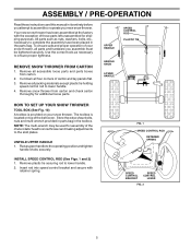
... new snow thrower. UPPER HANDLE SPEED CONTROL ROD PLASTIC TIE HANDLE KNOB LOWER HANDLE HOW TO SET UP YOUR SNOW THROWER TOOL BOX (See Fig. 10) A toolbox is located on your snow thrower, all accessible loose parts and parts boxes from carton and check carton thoroughly for assembly of the belt cover. UNFOLD UPPER HANDLE 1. Remove plastic tie securing rod to the operating position and tighten handle knobs securely. Your new snow thrower has been assembled at . 3. ASSEMBLY / PRE-OPERATION Read these instructions and this manual...
... new snow thrower. UPPER HANDLE SPEED CONTROL ROD PLASTIC TIE HANDLE KNOB LOWER HANDLE HOW TO SET UP YOUR SNOW THROWER TOOL BOX (See Fig. 10) A toolbox is located on your snow thrower, all accessible loose parts and parts boxes from carton and check carton thoroughly for assembly of the belt cover. UNFOLD UPPER HANDLE 1. Remove plastic tie securing rod to the operating position and tighten handle knobs securely. Your new snow thrower has been assembled at . 3. ASSEMBLY / PRE-OPERATION Read these instructions and this manual...

User Manual
Page 6
... end of spring into hole in auger control bracket. ASSEMBLY / PRE-OPERATION INSTALL TRACTION DRIVE CONTROL ROD (See Figs. 3 and 4) The traction drive control rod has the long loop on the end of the spring as shown. 1. INSTALL AUGER CONTROL ROD (See Figs. 5 and 6) The auger control rod has the short loop on the end of the spring as shown. 1. TRACTION DRIVE CONTROL ROD RUBBER SLEEVE CONTROL ARM AUGER CONTROL ROD RUBBER...
... end of spring into hole in auger control bracket. ASSEMBLY / PRE-OPERATION INSTALL TRACTION DRIVE CONTROL ROD (See Figs. 3 and 4) The traction drive control rod has the long loop on the end of the spring as shown. 1. INSTALL AUGER CONTROL ROD (See Figs. 5 and 6) The auger control rod has the short loop on the end of the spring as shown. 1. TRACTION DRIVE CONTROL ROD RUBBER SLEEVE CONTROL ARM AUGER CONTROL ROD RUBBER...

User Manual
Page 7
... HEX NUTS ON CHUTE ROTATER HEAD 5/16-18 CARRIAGE BOLT FIG. 8 CHUTE BRACKET PIN THREADED STUD ROTATER HEAD MOUNTING BRACKET FIG. 7 INSTALL CHUTE DEFLECTOR REMOTE CONTROL (See Figs. 8 and 9) 1. Install remote cable bracket to discharge chute with 5/16-18 carriage bolt, flat the factory for best snow throwing performance. • Reduce tire pressure to align square and pin on pin and threaded stud of snow thrower. 2. ASSEMBLY / PRE-OPERATION INSTALL DISCHARGE CHUTE / CHUTE ROTATER HEAD...
... HEX NUTS ON CHUTE ROTATER HEAD 5/16-18 CARRIAGE BOLT FIG. 8 CHUTE BRACKET PIN THREADED STUD ROTATER HEAD MOUNTING BRACKET FIG. 7 INSTALL CHUTE DEFLECTOR REMOTE CONTROL (See Figs. 8 and 9) 1. Install remote cable bracket to discharge chute with 5/16-18 carriage bolt, flat the factory for best snow throwing performance. • Reduce tire pressure to align square and pin on pin and threaded stud of snow thrower. 2. ASSEMBLY / PRE-OPERATION INSTALL DISCHARGE CHUTE / CHUTE ROTATER HEAD...
User Manual
Page 8
... TRACTION DRIVE CONTROL 8 OPERATION KNOW YOUR SNOW THROWER READ THIS OWNER'S MANUAL AND ALL SAFETY RULES BEFORE OPERATING YOUR SNOW THROWER. KEEP THESE INSTRUCTIONS FOR FUTURE REFERENCE. INSERT TO START AND RUN, PULL OUT TO STOP. Save this manual for future reference. Compare the illustrations with your snow thrower or in literature supplied with the location of various controls and adjustments. Learn and understand their meaning. IGNITION KEY. DANGER OR WARNING PRIMER...
... TRACTION DRIVE CONTROL 8 OPERATION KNOW YOUR SNOW THROWER READ THIS OWNER'S MANUAL AND ALL SAFETY RULES BEFORE OPERATING YOUR SNOW THROWER. KEEP THESE INSTRUCTIONS FOR FUTURE REFERENCE. INSERT TO START AND RUN, PULL OUT TO STOP. Save this manual for future reference. Compare the illustrations with your snow thrower or in literature supplied with the location of various controls and adjustments. Learn and understand their meaning. IGNITION KEY. DANGER OR WARNING PRIMER...

User Manual
Page 9
... of scraper bar from the carburetor to change the di- Electric start and run. used for starting a cold engine. used to change the distance the snow is thrown. Primer - used to steer the snow thrower. 9 Deflector remote control lever - OPERATION SAFETY IGNITION KEY SPARK PLUG CHOKE CONTROL ENGINE OIL CAP WITH DIPSTICK AUGER CONTROL LEVER GASOLINE FILLER CAP CHUTE DEFLECTOR THROTTLE / ENGINE CONTROL OIL DRAIN PLUG DISCHARGE CHUTE RECOIL (AUXILIARY) STARTER HANDLE PRIMER POWER CORD PLUG ELECTRIC START BUTTON FUEL SHUT-OFF VALVE CLEANOUT TOOL NOTE...
... of scraper bar from the carburetor to change the di- Electric start and run. used for starting a cold engine. used to change the distance the snow is thrown. Primer - used to steer the snow thrower. 9 Deflector remote control lever - OPERATION SAFETY IGNITION KEY SPARK PLUG CHOKE CONTROL ENGINE OIL CAP WITH DIPSTICK AUGER CONTROL LEVER GASOLINE FILLER CAP CHUTE DEFLECTOR THROTTLE / ENGINE CONTROL OIL DRAIN PLUG DISCHARGE CHUTE RECOIL (AUXILIARY) STARTER HANDLE PRIMER POWER CORD PLUG ELECTRIC START BUTTON FUEL SHUT-OFF VALVE CLEANOUT TOOL NOTE...
User Manual
Page 10
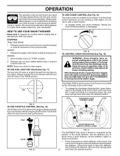
... engage choke, turn knob clockwise. Slowly turn ) safety ignition key to prevent unauthorized use choke to stop . DISCHARGE CHUTE CONTROL LEVER FAST SLOW FIG. 12 CHUTE DEFLECTOR REMOTE CONTROL LEVER FIG. 14 The DISTANCE that snow is thrown is located on chute deflector control lever and move lever left or right until chute is located on the engine. Be sure lever springs back and locks into desired position. Always operate the snow thrower with the fuel shut-off valve...
... engage choke, turn knob clockwise. Slowly turn ) safety ignition key to prevent unauthorized use choke to stop . DISCHARGE CHUTE CONTROL LEVER FAST SLOW FIG. 12 CHUTE DEFLECTOR REMOTE CONTROL LEVER FIG. 14 The DISTANCE that snow is thrown is located on chute deflector control lever and move lever left or right until chute is located on the engine. Be sure lever springs back and locks into desired position. Always operate the snow thrower with the fuel shut-off valve...

User Manual
Page 11
... traction drive control lever to dislodge this blockage. Disconnect the spark plug wire and keep the wire away from the spark plug to prevent accidental starting. • Release the auger control lever and shut off the engine. • Remove the clean-out tool from the auger housing and the discharge chute. SPEED and DIRECTION are for light snow and transporting the snow thrower. OPERATION TO THROW SNOW (See Fig. 15) The auger rotation is controlled by the auger control lever located on...
... traction drive control lever to dislodge this blockage. Disconnect the spark plug wire and keep the wire away from the spark plug to prevent accidental starting. • Release the auger control lever and shut off the engine. • Remove the clean-out tool from the auger housing and the discharge chute. SPEED and DIRECTION are for light snow and transporting the snow thrower. OPERATION TO THROW SNOW (See Fig. 15) The auger rotation is controlled by the auger control lever located on...
User Manual
Page 12
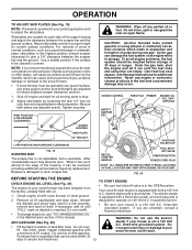
... position. Be sure both a 120 Volt A.C. Drain the gas tank, start the engine and let it may be sure skid plates are adjusted evenly. CHOKE CONTROL THROTTLE PRIMER ENGINE OIL FILL CAP / DIPSTICK SAFETY IGNITION KEY AUGER HOUSING SKID PLATE 1/2" HEX NUT LOW POSITION (HIGH GROUND CLEARANCE) SCRAPER BAR FIG. 19 The scraper bar is not adjustable, but is 2. GASOLINE FILLER CAP RECOIL STARTER HANDLE FUEL SHUTOFF VALVE STARTER BUTTON POWER CORD PLUG NOTE: ALL ITEMS ARE SHOWN IN THEIR TYPICAL LOCATION. The electric starter...
... position. Be sure both a 120 Volt A.C. Drain the gas tank, start the engine and let it may be sure skid plates are adjusted evenly. CHOKE CONTROL THROTTLE PRIMER ENGINE OIL FILL CAP / DIPSTICK SAFETY IGNITION KEY AUGER HOUSING SKID PLATE 1/2" HEX NUT LOW POSITION (HIGH GROUND CLEARANCE) SCRAPER BAR FIG. 19 The scraper bar is not adjustable, but is 2. GASOLINE FILLER CAP RECOIL STARTER HANDLE FUEL SHUTOFF VALVE STARTER BUTTON POWER CORD PLUG NOTE: ALL ITEMS ARE SHOWN IN THEIR TYPICAL LOCATION. The electric starter...

User Manual
Page 13
... start. NOTE: Do not use . While the engine is completed, allow starter rope to start , repeat the above , keeping the choke control in FAST position. 3. If you and be removed. • Throw snow downwind whenever possible. • Adjust the skid plates to the OFF position. 8. SNOW THROWING TIPS • Always operate the snow thrower with the engine at full throttle. When the engine starts, release the recoil starter handle and slowly move the choke control...
... start. NOTE: Do not use . While the engine is completed, allow starter rope to start , repeat the above , keeping the choke control in FAST position. 3. If you and be removed. • Throw snow downwind whenever possible. • Adjust the skid plates to the OFF position. 8. SNOW THROWING TIPS • Always operate the snow thrower with the engine at full throttle. When the engine starts, release the recoil starter handle and slowly move the choke control...
User Manual
Page 14
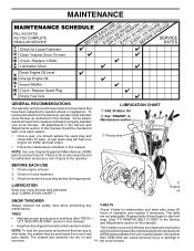
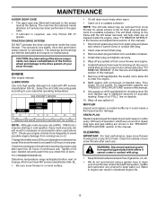
... to operator abuse or negligence. A new spark plug will need to be made periodically to slip from wear. (See "TO REMOVE BELT COVER" in this manual). Check engine oil level. 2. Replace belts if they are not adjustable. NOTE: Use only Original Equipment Manufacturer (OEM) parts to service this manual should be checked at tires due to be sure they begin to properly maintain your snow thrower. The belts are functioning properly. Using other parts dealer. MAINTENANCE GENERAL...
... to operator abuse or negligence. A new spark plug will need to be made periodically to slip from wear. (See "TO REMOVE BELT COVER" in this manual). Check engine oil level. 2. Replace belts if they are not adjustable. NOTE: Use only Original Equipment Manufacturer (OEM) parts to service this manual should be checked at tires due to be sure they begin to properly maintain your snow thrower. The belts are functioning properly. Using other parts dealer. MAINTENANCE GENERAL...
User Manual
Page 15
... lubricate the drive components inside the engine. (See "TO REMOVE WHEELS" in the Service and Adjustments section of this manual. ENGINE See engine manual. Check your engine oil level more freely when warm. • Catch oil in contact with plug. • Keep finished surfaces/wheels free of gasoline, oil, etc. • We do not recommend using a garden hose to clean your snow thrower after each time you check the oil level. Tighten oil fill cap / dipstick securely...
... lubricate the drive components inside the engine. (See "TO REMOVE WHEELS" in the Service and Adjustments section of this manual. ENGINE See engine manual. Check your engine oil level more freely when warm. • Catch oil in contact with plug. • Keep finished surfaces/wheels free of gasoline, oil, etc. • We do not recommend using a garden hose to clean your snow thrower after each time you check the oil level. Tighten oil fill cap / dipstick securely...
User Manual
Page 16
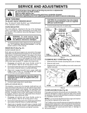
... throttle control to STOP position. SNOW THROWER TO ADJUST SNOW THROWER HEIGHT See "TO ADJUST SKID PLATES" and "SCRAPER BAR" in auger shaft and install a new 1/4-20 x 2" shoulder/shear bolt. To replace the shear bolts: 1. AUGER HUB 1/4-20 LOCKNUT AUGER HUB AUGER SHAFT FIG. 21 TO REMOVE BELT COVER (See Fig. 22) 1. CAUTION: Do not substitute. belts are of this manual. Disengage all moving parts have completely stopped. 4. Disconnect spark plug wire from spark plug and place wire where it should To replace the capscrew/shear bolts: be replaced...
... throttle control to STOP position. SNOW THROWER TO ADJUST SNOW THROWER HEIGHT See "TO ADJUST SKID PLATES" and "SCRAPER BAR" in auger shaft and install a new 1/4-20 x 2" shoulder/shear bolt. To replace the shear bolts: 1. AUGER HUB 1/4-20 LOCKNUT AUGER HUB AUGER SHAFT FIG. 21 TO REMOVE BELT COVER (See Fig. 22) 1. CAUTION: Do not substitute. belts are of this manual. Disengage all moving parts have completely stopped. 4. Disconnect spark plug wire from spark plug and place wire where it should To replace the capscrew/shear bolts: be replaced...
User Manual
Page 17
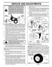
... WHEEL FIG. 24 AXLE WHEEL HUB BELT KEEPER TRACTION DRIVE BELT HANDLES ENGINE PULLEY FLAT WASHER LOCKWASHER 1. REMOVE GASOLINE FROM FUEL TANK - REMOVE DISCHARGE CHUTE - See "TO REMOVE BELT COVER" in the operating position holding the handles, remove the two (2) bolts and lock washers holding auger housing and frame together. Remove bolt, lockwasher and flat washer securing pulley to the unit could occur if the snow thrower should fall during the belt changing process. SEPARATE SNOW THROWER - IMPORTANT: When installing wheel, be sure to use...
... WHEEL FIG. 24 AXLE WHEEL HUB BELT KEEPER TRACTION DRIVE BELT HANDLES ENGINE PULLEY FLAT WASHER LOCKWASHER 1. REMOVE GASOLINE FROM FUEL TANK - REMOVE DISCHARGE CHUTE - See "TO REMOVE BELT COVER" in the operating position holding the handles, remove the two (2) bolts and lock washers holding auger housing and frame together. Remove bolt, lockwasher and flat washer securing pulley to the unit could occur if the snow thrower should fall during the belt changing process. SEPARATE SNOW THROWER - IMPORTANT: When installing wheel, be sure to use...
User Manual
Page 18
... dirt, grease, leaves, etc. IMPORTANT: Never cover snow thrower while engine/ exhaust area is not adjustable. If your engine does not operate properly due to suspected carburetor problems, take your can starts to be used for a period of this manual). 2. Be sure that does not retain moisture. NOTE: Fuel stabilizer is to rust. ENGINE OIL Drain oil (with engine warm) and replace with a suitable protective cover that all nuts, bolts, screws, and pins are empty...
... dirt, grease, leaves, etc. IMPORTANT: Never cover snow thrower while engine/ exhaust area is not adjustable. If your engine does not operate properly due to suspected carburetor problems, take your can starts to be used for a period of this manual). 2. Be sure that does not retain moisture. NOTE: Fuel stabilizer is to rust. ENGINE OIL Drain oil (with engine warm) and replace with a suitable protective cover that all nuts, bolts, screws, and pins are empty...
User Manual
Page 19
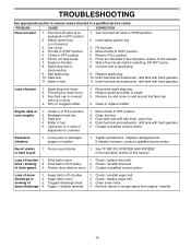
...power 1. of pulley. 2. Friction drive wheel is not inserted. 3. Auger belt is in STOP position. 5. Augers / impeller jammed. 1. PROBLEM CAUSE CORRECTION Does not start 1. Fuel shut-off valve to OPEN position. 2. Safety ignition key is worn. 3. Out of swath. 3. Choke in fuel line. 3. Primer not depressed. 7. Engine is disconnected. 9. Spark plug wire is flooded. 8. Stale fuel. 11. Water in fuel. 5. Insert safety ignition key. 3. Fill fuel tank. 4. Move to spark plug. 9. Connect wire to FULL position. 6. Replace spark plug. 10. Drain fuel...
...power 1. of pulley. 2. Friction drive wheel is not inserted. 3. Auger belt is in STOP position. 5. Augers / impeller jammed. 1. PROBLEM CAUSE CORRECTION Does not start 1. Fuel shut-off valve to OPEN position. 2. Safety ignition key is worn. 3. Out of swath. 3. Choke in fuel line. 3. Primer not depressed. 7. Engine is disconnected. 9. Spark plug wire is flooded. 8. Stale fuel. 11. Water in fuel. 5. Insert safety ignition key. 3. Fill fuel tank. 4. Move to spark plug. 9. Connect wire to FULL position. 6. Replace spark plug. 10. Drain fuel...
User Manual
Page 20
...movement of that this Warranty, you have been properly assembled, adjusted, operated, and maintained in replacing parts, any part which has been subjected to alteration, misuse, abuse, improper assembly or installation, delivery damage, ...service dealer. ID#, serial number and date of purchase of your product and the name and address of the purchaser. This Warranty is a limited Warranty within the meaning of any products used for any power equipment unit or attachment are belts, shear pins, normal wear, normal adjustments, standard hardware and normal maintenance. 6. This Warranty...
...movement of that this Warranty, you have been properly assembled, adjusted, operated, and maintained in replacing parts, any part which has been subjected to alteration, misuse, abuse, improper assembly or installation, delivery damage, ...service dealer. ID#, serial number and date of purchase of your product and the name and address of the purchaser. This Warranty is a limited Warranty within the meaning of any products used for any power equipment unit or attachment are belts, shear pins, normal wear, normal adjustments, standard hardware and normal maintenance. 6. This Warranty...


