
User Manual
Page 2
...it . • Keep machine free of -control and • Never tamper with manufacturer's recommended parts, when necessary. • Mower blades are subject to the machine and the mowing activity. These operators should evaluate their proper tipover accidents, which can occur if the .... • Remove obstacles such as rocks, toys, wire, etc., turn over if a wheel is clear of other fuels. The mower could be seriously injured or interfere with the engine running . They may obscure vision. operation regularly. Frequently check components and replace with ...
...it . • Keep machine free of -control and • Never tamper with manufacturer's recommended parts, when necessary. • Mower blades are subject to the machine and the mowing activity. These operators should evaluate their proper tipover accidents, which can occur if the .... • Remove obstacles such as rocks, toys, wire, etc., turn over if a wheel is clear of other fuels. The mower could be seriously injured or interfere with the engine running . They may obscure vision. operation regularly. Frequently check components and replace with ...

User Manual
Page 3
... on the slope. • Avoid starting when setting up and down a hill in reverse unless absolutely necessary. SAFETY RULES SAFE OPERATION PRACTICES FOR RIDE-ON MOWERS • Be sure the area is clear of a load, while on a slope, is dangerous.
... on the slope. • Avoid starting when setting up and down a hill in reverse unless absolutely necessary. SAFETY RULES SAFE OPERATION PRACTICES FOR RIDE-ON MOWERS • Be sure the area is clear of a load, while on a slope, is dangerous.

User Manual
Page 5
... Adapter Steering Wheel Insert Seat (4) Clevis Pins (4) Washers 3/8 x 3/4 x 14 Ga. (4) Retainer Springs (double loop) (4) Locknuts 3/8-16 Nose Roller (1) Washer 17/32 x 1-3/16 x 12 Gauge (1) Knob Mower (5) Retainer Springs (double loop) (2) Retainer Springs (single loop) (2)Flanged Pins (1)Front Plate Assembly (2) Locknuts 5/16-18 Rod Retainer Spring Nose Roller Brackets (2) Hex Bolts 5/16...
... Adapter Steering Wheel Insert Seat (4) Clevis Pins (4) Washers 3/8 x 3/4 x 14 Ga. (4) Retainer Springs (double loop) (4) Locknuts 3/8-16 Nose Roller (1) Washer 17/32 x 1-3/16 x 12 Gauge (1) Knob Mower (5) Retainer Springs (double loop) (2) Retainer Springs (single loop) (2)Flanged Pins (1)Front Plate Assembly (2) Locknuts 5/16-18 Rod Retainer Spring Nose Roller Brackets (2) Hex Bolts 5/16...
User Manual
Page 6
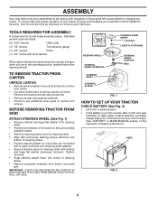
TOOLS REQUIRED FOR ASSEMBLY A socket wrench set will make assembly easier. Remove end panels and lay side panels flat. • Remove mower and packing materials. • Check for shipping purposes. IMPORTANT: CHECK FOR AND REMOVE ANY STAPLES IN SKID THAT MAY PUNCTURE TIRES WHERE TRACTOR IS TO ...
TOOLS REQUIRED FOR ASSEMBLY A socket wrench set will make assembly easier. Remove end panels and lay side panels flat. • Remove mower and packing materials. • Check for shipping purposes. IMPORTANT: CHECK FOR AND REMOVE ANY STAPLES IN SKID THAT MAY PUNCTURE TIRES WHERE TRACTOR IS TO ...
User Manual
Page 7
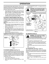
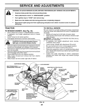
... "TO TRANSPORT" in properpositionwhenoperatingmower.Besuretheyareproperly adjusted to tractor. • Pivot seat upward and remove from the skid. ASSEMBLE GAUGE WHEELS TO MOWER DECK (See Fig. 4) The gauge wheels are on top. Be sure tractor is clear of other people and objects. • Be.... Assemble gauge wheels as shown using shoulder bolts, 3/8 washers and 3/8-16 center locknuts and tighten securely. • For ease of mower to tractor assembly, raise gauge wheels to remove the tractor from the cardboard packing. RETAINER SPRING PIN SHOULDER BOLT ADJUSTING BAR GAUGE WHEEL ...
... "TO TRANSPORT" in properpositionwhenoperatingmower.Besuretheyareproperly adjusted to tractor. • Pivot seat upward and remove from the skid. ASSEMBLE GAUGE WHEELS TO MOWER DECK (See Fig. 4) The gauge wheels are on top. Be sure tractor is clear of other people and objects. • Be.... Assemble gauge wheels as shown using shoulder bolts, 3/8 washers and 3/8-16 center locknuts and tighten securely. • For ease of mower to tractor assembly, raise gauge wheels to remove the tractor from the cardboard packing. RETAINER SPRING PIN SHOULDER BOLT ADJUSTING BAR GAUGE WHEEL ...

User Manual
Page 8
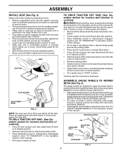
...brackets and install rod and retainer spring. LOCK NUT HEX BOLT ROD TAB HOLE "B" BRACKET "A" BRACKET 02612 RETAINER SPRING NOSE ROLLER FIG. 5 INSTALL MOWER AND DRIVE BELT (See Figs. 6 and 7) Be sure tractor is spring loaded. Have a tight grip on head of tractor. Retain with double... Be sure bracket tabs are raised with notch on rod and engage slowly. • Connect anti-sway bar to left side of mower deck. • Slide mower under left footrest and retain with double loop retainer spring. • If equipped, turn height adjustment knob counterclockwise until it stops....
...brackets and install rod and retainer spring. LOCK NUT HEX BOLT ROD TAB HOLE "B" BRACKET "A" BRACKET 02612 RETAINER SPRING NOSE ROLLER FIG. 5 INSTALL MOWER AND DRIVE BELT (See Figs. 6 and 7) Be sure tractor is spring loaded. Have a tight grip on head of tractor. Retain with double... Be sure bracket tabs are raised with notch on rod and engage slowly. • Connect anti-sway bar to left side of mower deck. • Slide mower under left footrest and retain with double loop retainer spring. • If equipped, turn height adjustment knob counterclockwise until it stops....
User Manual
Page 9
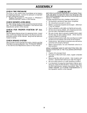
...USE YOUR TRACTOR, PAY EXTRA ATTENTION TO THE FOLLOWING IMPORTANT ITEMS: ✓ Engine oil is at the factory for replacing motion, mower drive, and mower blade drive belts in the Operation section of this manual. Operate them before operating your tractor, check to PSI shown in the... section of this manual. Verify that the brake is important for the first time. their location and function. See "TO LEVEL MOWER HOUSING" in "PRODUCT SPECIFICATIONS" section of this manual. ✓CHECKLIST BEFOREYOU OPERATE AND ENJOYYOUR NEW TRACTOR, WE WISH TO ASSURE THAT YOU...
...USE YOUR TRACTOR, PAY EXTRA ATTENTION TO THE FOLLOWING IMPORTANT ITEMS: ✓ Engine oil is at the factory for replacing motion, mower drive, and mower blade drive belts in the Operation section of this manual. Operate them before operating your tractor, check to PSI shown in the... section of this manual. Verify that the brake is important for the first time. their location and function. See "TO LEVEL MOWER HOUSING" in "PRODUCT SPECIFICATIONS" section of this manual. ✓CHECKLIST BEFOREYOU OPERATE AND ENJOYYOUR NEW TRACTOR, WE WISH TO ASSURE THAT YOU...

User Manual
Page 10
... OFF LIGHTS ON P ENGINE ON ENGINE START PARKING BRAKE PARKING BRAKE PARKING BRAKE LOCKED UNLOCKED OVER TEMP LIGHT FUEL OIL PRESSURE BATTERY REVERSE FORWARD MOWER HEIGHT 15 MOWER LIFT 15 ATTACHMENT ATTACHMENT CLUTCH ENGAGED CLUTCH DISENGAGED DANGER, KEEP HANDS AND FEET AWAY KEEP AREA CLEAR SLOPE HAZARDS (SEE SAFETY RULES SECTION) FREE...
... OFF LIGHTS ON P ENGINE ON ENGINE START PARKING BRAKE PARKING BRAKE PARKING BRAKE LOCKED UNLOCKED OVER TEMP LIGHT FUEL OIL PRESSURE BATTERY REVERSE FORWARD MOWER HEIGHT 15 MOWER LIFT 15 ATTACHMENT ATTACHMENT CLUTCH ENGAGED CLUTCH DISENGAGED DANGER, KEEP HANDS AND FEET AWAY KEEP AREA CLEAR SLOPE HAZARDS (SEE SAFETY RULES SECTION) FREE...
User Manual
Page 11
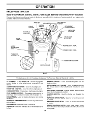
... DRIVE PEDAL - HOURMETER - ATTACHMENT LIFT LEVER - Used to the safety standards of various controls and adjustments. Used to engage the mower blades, or other attachments mounted to your tractor. BRAKE PEDAL - IGNITION SWITCH - CRUISE CONTROL LEVER - OPERATION KNOW YOUR TRACTOR READ... YOUR TRACTOR Compare the illustrations with your tractor. FORWARD DRIVE PEDAL - THROTTLE CONTROL - Used to raise and lower the mower deck or other attachments mounted to your tractor to release attachment lift lever when changing its position. Indicates charging (+) or ...
... DRIVE PEDAL - HOURMETER - ATTACHMENT LIFT LEVER - Used to the safety standards of various controls and adjustments. Used to engage the mower blades, or other attachments mounted to your tractor. BRAKE PEDAL - IGNITION SWITCH - CRUISE CONTROL LEVER - OPERATION KNOW YOUR TRACTOR READ... YOUR TRACTOR Compare the illustrations with your tractor. FORWARD DRIVE PEDAL - THROTTLE CONTROL - Used to raise and lower the mower deck or other attachments mounted to your tractor to release attachment lift lever when changing its position. Indicates charging (+) or ...

User Manual
Page 12
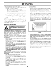
.... • Turn knob clockwise ( ) to raise cutting height. • Turn knob counterclockwise ( ) to begin movement. TO ADJUST MOWER CUTTING HEIGHT (See Fig. 8) The cutting height is controlled by the operator to leave the seat without first setting the parking ...PEDAL "DISENGAGED" "DRIVE" POSITION POSITION CRUISE CONTROL LEVER PARKING BRAKE "ENGAGED" POSITION FIG. 8 STOPPING (See Fig. 8) MOWER BLADES - • To stop mower blades,move throttle control to slow position and allowing engine to idle before leaving the operator's position; Ground speed increases the further...
.... • Turn knob clockwise ( ) to raise cutting height. • Turn knob counterclockwise ( ) to begin movement. TO ADJUST MOWER CUTTING HEIGHT (See Fig. 8) The cutting height is controlled by the operator to leave the seat without first setting the parking ...PEDAL "DISENGAGED" "DRIVE" POSITION POSITION CRUISE CONTROL LEVER PARKING BRAKE "ENGAGED" POSITION FIG. 8 STOPPING (See Fig. 8) MOWER BLADES - • To stop mower blades,move throttle control to slow position and allowing engine to idle before leaving the operator's position; Ground speed increases the further...
User Manual
Page 13
...8226; Raise attachment lift to brake position and engage parking brake. OPERATION The cutting height range is approximately 1-1/2" to slowest setting. JUST MOWER CUTTING HEIGHT" in the disengaged position. • Select desired height of this manual). • Remove retainer spring and clevis pin ...are measured from hesitating or cutting off the engine. IMPORTANT:BE SURETO READJUST GAUGEWHEELS IFYOU CHANGE THE CUTTING HEIGHT OF THE MOWER DECK. Gauge wheels then keep the deck in proper position to align holes in place. RETAINER SPRING 01977 ATTACHMENT CLUTCH SWITCH...
...8226; Raise attachment lift to brake position and engage parking brake. OPERATION The cutting height range is approximately 1-1/2" to slowest setting. JUST MOWER CUTTING HEIGHT" in the disengaged position. • Select desired height of this manual). • Remove retainer spring and clevis pin ...are measured from hesitating or cutting off the engine. IMPORTANT:BE SURETO READJUST GAUGEWHEELS IFYOU CHANGE THE CUTTING HEIGHT OF THE MOWER DECK. Gauge wheels then keep the deck in proper position to align holes in place. RETAINER SPRING 01977 ATTACHMENT CLUTCH SWITCH...
User Manual
Page 15
... engine and set . • Disengage transmission by selecting a low enough gear to give best performance of this procedure there will plug mower and leave undesirable clumps. Make first cut area to operating position. • Allow one or two rounds, mow in the ...finished (See Fig. 12). the second to assure better mowing performance and proper discharge of cut . ning. See "TO LEVEL MOWER HOUSING" in the Service and Adjustments section of the attachment being removed from hydraulic drive system. • Shut- mended that clippings will ...
... engine and set . • Disengage transmission by selecting a low enough gear to give best performance of this procedure there will plug mower and leave undesirable clumps. Make first cut area to operating position. • Allow one or two rounds, mow in the ...finished (See Fig. 12). the second to assure better mowing performance and proper discharge of cut . ning. See "TO LEVEL MOWER HOUSING" in the Service and Adjustments section of the attachment being removed from hydraulic drive system. • Shut- mended that clippings will ...

User Manual
Page 16
... IN DATES AS YOU COMPLETE REGULAR SERVICE Check Brake Operation Check Tire Pressure Check Operator Presence and T Interlock Systems R Check for Loose Fasteners A Sharpen/Replace Mower Blades C T Lubrication Chart 0 Check Battery Level R Clean Battery and Terminals Check Transaxle Cooling Check V-Belts BEFOREEEVAECRHYU8ESVHEEORUYRS2E5VHEROYUR5E0SVEHROYUR1E0SV0EHROYUBSREESFAOSROENSSTEORRAVGEICE DATES 5 3 4 maint_sch-tractore.new1 Check Engine Oil Level Change...
... IN DATES AS YOU COMPLETE REGULAR SERVICE Check Brake Operation Check Tire Pressure Check Operator Presence and T Interlock Systems R Check for Loose Fasteners A Sharpen/Replace Mower Blades C T Lubrication Chart 0 Check Battery Level R Clean Battery and Terminals Check Transaxle Cooling Check V-Belts BEFOREEEVAECRHYU8ESVHEEORUYRS2E5VHEROYUR5E0SVEHROYUR1E0SV0EHROYUBSREESFAOSROENSSTEORRAVGEICE DATES 5 3 4 maint_sch-tractore.new1 Check Engine Oil Level Change...
User Manual
Page 17
...off the engine. • The attachment clutch should never operate unless the operator is in the seat. CENTER HOLE For best results mower blades must be sharpened with the ground. torque). Tire sealant also prevents tire dry rot and corrosion. IMPORTANT: TO ENSURE PROPER ASSEMBLY,...or remove caps or covers. Lbs. However, periodic charging of the battery with an automotive charger will cause excessive vibration and eventual damage to mower and engine. • The blade can be adjusted. (See "TO ADJUST BRAKE" in a horizontal position. MAINTENANCE TRACTOR Always observe safety...
...off the engine. • The attachment clutch should never operate unless the operator is in the seat. CENTER HOLE For best results mower blades must be sharpened with the ground. torque). Tire sealant also prevents tire dry rot and corrosion. IMPORTANT: TO ENSURE PROPER ASSEMBLY,...or remove caps or covers. Lbs. However, periodic charging of the battery with an automotive charger will cause excessive vibration and eventual damage to mower and engine. • The blade can be adjusted. (See "TO ADJUST BRAKE" in a horizontal position. MAINTENANCE TRACTOR Always observe safety...
User Manual
Page 19
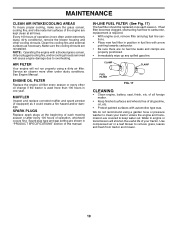
.... We do not recommend using a dirty air filter. Make sure the cooling shrouds are covered to remove grass, leaves and trash from tractor and mower. 19 IN-LINE FUEL FILTER (See Fig. 17) The fuel filter should be replaced once each mowing season or after every 100 hours of...
.... We do not recommend using a dirty air filter. Make sure the cooling shrouds are covered to remove grass, leaves and trash from tractor and mower. 19 IN-LINE FUEL FILTER (See Fig. 17) The fuel filter should be replaced once each mowing season or after every 100 hours of...
User Manual
Page 20
... suspension arms on outward pointing deck pins. SUSPENSION ARMS BELT TENSION ROD (DISENGAGED POSITION) CHASSIS BRACKET RETAINER SPRING LOCK BRACKET FRONT MOWER BRACKET ELECTRIC CLUTCH PULLEY FRONT PLATE ASSEMBLY SINGLE LOOP RETAINER SPRING DOUBLE LOOP RETAINER SPRING FLANGED PIN USE PLIERS FOR RETAINER SPRINGS LOOP... ANTI-SWAY BAR SUSPENSION ARMS DOUBLE LOOP RETAINER SPRINGS (Outward pointing deck pins) FIG. 18 20 02565 DEFLECTOR SHIELD TO INSTALL MOWER Be sure tractor is on rod and release slowly. • Remove retainer spring holding anti-swaybar to chassis bracket and disengage ...
... suspension arms on outward pointing deck pins. SUSPENSION ARMS BELT TENSION ROD (DISENGAGED POSITION) CHASSIS BRACKET RETAINER SPRING LOCK BRACKET FRONT MOWER BRACKET ELECTRIC CLUTCH PULLEY FRONT PLATE ASSEMBLY SINGLE LOOP RETAINER SPRING DOUBLE LOOP RETAINER SPRING FLANGED PIN USE PLIERS FOR RETAINER SPRINGS LOOP... ANTI-SWAY BAR SUSPENSION ARMS DOUBLE LOOP RETAINER SPRINGS (Outward pointing deck pins) FIG. 18 20 02565 DEFLECTOR SHIELD TO INSTALL MOWER Be sure tractor is on rod and release slowly. • Remove retainer spring holding anti-swaybar to chassis bracket and disengage ...

User Manual
Page 21
...BE LEVEL SIDE-TO-SIDE. CAUTION: Belt tension rod is parked on both front links an equal number of turns. NOTE: Each full turn of mower to highest position. NOTE: To assist in locating hole in flanged pin, the hole in flated (See "PRODUCT SPECIFICATIONS" section of... ASSEMBLY 02517 TRUNNION NUT "C" FIG. 20 FIG. 22 21 Distance "A" on both front links. • To raise front of blade, loosen nut "D" from mower suspension. • Raise deck to ground level at front than rear, tighten nut "D" against trunnion on both front links an equal number of adjustment nut...
...BE LEVEL SIDE-TO-SIDE. CAUTION: Belt tension rod is parked on both front links an equal number of turns. NOTE: Each full turn of mower to highest position. NOTE: To assist in locating hole in flanged pin, the hole in flated (See "PRODUCT SPECIFICATIONS" section of... ASSEMBLY 02517 TRUNNION NUT "C" FIG. 20 FIG. 22 21 Distance "A" on both front links. • To raise front of blade, loosen nut "D" from mower suspension. • Raise deck to ground level at front than rear, tighten nut "D" against trunnion on both front links an equal number of adjustment nut...

User Manual
Page 22
... belt in this section of manual). • Install belt into upper groove of R.H. SECONDARY L.H. Engage parking brake. • Remove mower (See "TO REMOVE MOWER" in lower groove of R.H. mandrel pulley. • Remove belt from lock bracket. mandrel pulley. • Remove belt from rear ...all grooves properly. MANDREL IDLER ARM IDLER PULLEY SPRING SECONDARY SPRING ARM CENTER MANDREL FIG. 23 R.H. SERVICE AND ADJUSTMENTS TO REPLACE MOWER DRIVE BELT MOWER DRIVE BELT REMOVAL (See Fig. 23) • Park tractor on level surface. CAUTION: Rod is in all screws. •...
... belt in this section of manual). • Install belt into upper groove of R.H. SECONDARY L.H. Engage parking brake. • Remove mower (See "TO REMOVE MOWER" in lower groove of R.H. mandrel pulley. • Remove belt from lock bracket. mandrel pulley. • Remove belt from rear ...all grooves properly. MANDREL IDLER ARM IDLER PULLEY SPRING SECONDARY SPRING ARM CENTER MANDREL FIG. 23 R.H. SERVICE AND ADJUSTMENTS TO REPLACE MOWER DRIVE BELT MOWER DRIVE BELT REMOVAL (See Fig. 23) • Park tractor on level surface. CAUTION: Rod is in all screws. •...

User Manual
Page 23
... on brake rod. • If distance is in "transmission disengaged" position. TO ADJUST BRAKE • Depress brake pedal all belt guides and keepers. • Install mower (See "TO INSTALL MOWER" in this manual. 23 BELT REMOVAL • Remove mower (See "TO REMOVE MOWER" in this sec- tion of left footrest.
... on brake rod. • If distance is in "transmission disengaged" position. TO ADJUST BRAKE • Depress brake pedal all belt guides and keepers. • Install mower (See "TO INSTALL MOWER" in this manual. 23 BELT REMOVAL • Remove mower (See "TO REMOVE MOWER" in this sec- tion of left footrest.
User Manual
Page 26
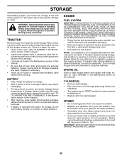
Allow the engine to cool before painting. When mower is to be used for 30 days or more. Inspect moving parts for winter storage. ENGINE FUEL SYSTEM IMPORTANT: IT IS IMPORTANT TO PREVENT GUM ... will cause problems. • If possible, store your tractor indoors and cover it to give protection from tractor for damage, breakage and wear. TRACTOR Remove mower from dust and dirt. • Cover your tractor with a suitable protective cover that all nuts, bolts and screws are empty. • Never use plastic. Do...
Allow the engine to cool before painting. When mower is to be used for 30 days or more. Inspect moving parts for winter storage. ENGINE FUEL SYSTEM IMPORTANT: IT IS IMPORTANT TO PREVENT GUM ... will cause problems. • If possible, store your tractor indoors and cover it to give protection from tractor for damage, breakage and wear. TRACTOR Remove mower from dust and dirt. • Cover your tractor with a suitable protective cover that all nuts, bolts and screws are empty. • Never use plastic. Do...


