
User Manual
Page 2
..., rather than from a gasoline dispenser nozzle. - temperatures before starting extension cords certified CSA/UL. Do not use snow thrower on a trailer with the controls and use electric starting engine (motor). Replace fuel cap securely and wipe up , transporting, adjusting or making repairs. Never store fuel or snow thrower with fuel in contact with care; YOUR SAFETY IS INVOLVED. • Do not operate the equipment without proper recommended by manufacturer). Avoid loose...
..., rather than from a gasoline dispenser nozzle. - temperatures before starting extension cords certified CSA/UL. Do not use snow thrower on a trailer with the controls and use electric starting engine (motor). Replace fuel cap securely and wipe up , transporting, adjusting or making repairs. Never store fuel or snow thrower with fuel in contact with care; YOUR SAFETY IS INVOLVED. • Do not operate the equipment without proper recommended by manufacturer). Avoid loose...
User Manual
Page 3
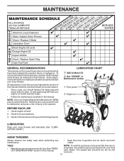
.... • Maintain or replace safety and instruction labels, as necessary. • Run the snow thrower, with fuel in maintaining, caring for any problem you to +40°F) SAE 0W-30 (below 0°F) Oil Capacity: 22 Ounces SERIAL NUMBER Spark Plug: Champion RN4C (Gap: .030") DATE OF PURCHASE THE MODEL AND SERIAL NUMBERS WILL BE FOUND ON A DECAL ATTACHED TO THE REAR OF THE SNOW THROWER HOUSING. MAINTENANCE AND STORAGE • Check shear bolts and other such...
.... • Maintain or replace safety and instruction labels, as necessary. • Run the snow thrower, with fuel in maintaining, caring for any problem you to +40°F) SAE 0W-30 (below 0°F) Oil Capacity: 22 Ounces SERIAL NUMBER Spark Plug: Champion RN4C (Gap: .030") DATE OF PURCHASE THE MODEL AND SERIAL NUMBERS WILL BE FOUND ON A DECAL ATTACHED TO THE REAR OF THE SNOW THROWER HOUSING. MAINTENANCE AND STORAGE • Check shear bolts and other such...
User Manual
Page 5
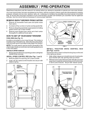
... proper operation of your new snow thrower. NOTE: The multi-wrench may be tightened securely. Remove all parts and hardware you attempt to assemble or operate your snow thrower, all packing materials except plastic tie holding speed control rod to lower handle. 4. HOW TO SET UP YOUR SNOW THROWER TOOL BOX (See Fig. 11) A toolbox is located on top of rod into hole in drive control bracket. Store the extra shear bolts, nuts...
... proper operation of your new snow thrower. NOTE: The multi-wrench may be tightened securely. Remove all parts and hardware you attempt to assemble or operate your snow thrower, all packing materials except plastic tie holding speed control rod to lower handle. 4. HOW TO SET UP YOUR SNOW THROWER TOOL BOX (See Fig. 11) A toolbox is located on top of rod into hole in drive control bracket. Store the extra shear bolts, nuts...

User Manual
Page 6
... bracket. 4. Position chute rotater head over chute bracket. Place discharge chute assembly on pin and threaded stud of chute rotater head with holes in your parts bag may be used to align square and pin on rod and insert end of rod into control arm with retainer spring. ASSEMBLY / PRE-OPERATION TRACTION DRIVE CONTROL LEVER RETAINER SPRING AUGER CONTROL ROD RETAINER SPRING AUGER CONTROL LEVER TRACTION DRIVE CONTROL ROD DRIVE CONTROL BRACKET FIG. 4 INSTALL AUGER CONTROL ROD (See Figs. 5 and 6) The auger control rod has...
... bracket. 4. Position chute rotater head over chute bracket. Place discharge chute assembly on pin and threaded stud of chute rotater head with holes in your parts bag may be used to align square and pin on rod and insert end of rod into control arm with retainer spring. ASSEMBLY / PRE-OPERATION TRACTION DRIVE CONTROL LEVER RETAINER SPRING AUGER CONTROL ROD RETAINER SPRING AUGER CONTROL LEVER TRACTION DRIVE CONTROL ROD DRIVE CONTROL BRACKET FIG. 4 INSTALL AUGER CONTROL ROD (See Figs. 5 and 6) The auger control rod has...

User Manual
Page 7
... weight bag in chute deflector as shown. 4. MOUNTING BAR CLAMP WEIGHT BAG FLAT WASHER 5/16-18 LOCKNUT FIG. 8 CHUTE DEFLECTOR CONTROL LEVER FIG. 9 5/16-18 x 1-1/2 CAPSCREWS AUGER HOUSING FIG. 10 CHECK TIRE PRESSURE The tires on your snow thrower were overinflated at front edge of the auger housing. ASSEMBLY / PRE-OPERATION INSTALL CHUTE DEFLECTOR REMOTE CONTROL (See Figs. 8 and 9) 1. Install remote cable eyelet to chute deflector with 1/4-20 shoulder bolt, nylon washer...
... weight bag in chute deflector as shown. 4. MOUNTING BAR CLAMP WEIGHT BAG FLAT WASHER 5/16-18 LOCKNUT FIG. 8 CHUTE DEFLECTOR CONTROL LEVER FIG. 9 5/16-18 x 1-1/2 CAPSCREWS AUGER HOUSING FIG. 10 CHECK TIRE PRESSURE The tires on your snow thrower were overinflated at front edge of the auger housing. ASSEMBLY / PRE-OPERATION INSTALL CHUTE DEFLECTOR REMOTE CONTROL (See Figs. 8 and 9) 1. Install remote cable eyelet to chute deflector with 1/4-20 shoulder bolt, nylon washer...

User Manual
Page 9
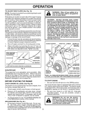
... PLUG CHOKE CONTROL OPERATION ENGINE OIL CAP AUGER DISCHARGE CHUTE CONTROL LEVER WITH DIPSTICK CONTROL LEVER DRIVE SPEED DEFLECTOR REMOTE CONTROL LEVER CONTROL LEVER GASOLINE FILLER CAP CHUTE DEFLECTOR TRACTION DRIVE CONTROL LEVER THROTTLE / ENGINE CONTROL RECOIL (AUXILIARY) STARTER HANDLE PRIMER POWER CORD PLUG ELECTRIC START BUTTON OIL DRAIN PLUG FUEL SHUT-OFF VALVE DISCHARGE CHUTE NOTE: ITEMS ABOVE ARE SHOWN IN THEIR TYPICAL LOCATION ON THE ENGINE. Toolbox - must be inserted for starting a cold engine. used to adjust height of snow thrower. used...
... PLUG CHOKE CONTROL OPERATION ENGINE OIL CAP AUGER DISCHARGE CHUTE CONTROL LEVER WITH DIPSTICK CONTROL LEVER DRIVE SPEED DEFLECTOR REMOTE CONTROL LEVER CONTROL LEVER GASOLINE FILLER CAP CHUTE DEFLECTOR TRACTION DRIVE CONTROL LEVER THROTTLE / ENGINE CONTROL RECOIL (AUXILIARY) STARTER HANDLE PRIMER POWER CORD PLUG ELECTRIC START BUTTON OIL DRAIN PLUG FUEL SHUT-OFF VALVE DISCHARGE CHUTE NOTE: ITEMS ABOVE ARE SHOWN IN THEIR TYPICAL LOCATION ON THE ENGINE. Toolbox - must be inserted for starting a cold engine. used to adjust height of snow thrower. used...

User Manual
Page 10
... choke control is located on the engine. Full throttle offers the best snow thrower performance. WARNING: If the discharge chute or auger become clogged, shut-off valve is located beneath the fuel tank on discharge chute control lever and move lever forward to disengage. The DIRECTION in the OPEN position. Be sure lever springs back and locks into desired position. Set the deflector low to prevent unauthorized use to start a warm engine. • To engage choke, turn ) safety ignition...
... choke control is located on the engine. Full throttle offers the best snow thrower performance. WARNING: If the discharge chute or auger become clogged, shut-off valve is located beneath the fuel tank on discharge chute control lever and move lever forward to disengage. The DIRECTION in the OPEN position. Be sure lever springs back and locks into desired position. Set the deflector low to prevent unauthorized use to start a warm engine. • To engage choke, turn ) safety ignition...

User Manual
Page 11
... snow throwing process. DRIVE SPEED CONTROL LEVER FIG. 17 POWER STEERING OPERATION (See Fig. 18) Steering triggers are used to stop the forward or reverse movement of each handle. It is squeezed, it to stop throwing snow. Be sure lever springs back and locks into desired position. Damage to desired position BEFORE engaging the traction drive control lever. NOTE: When both traction drive and auger control levers are for light snow and transporting the snow thrower...
... snow throwing process. DRIVE SPEED CONTROL LEVER FIG. 17 POWER STEERING OPERATION (See Fig. 18) Steering triggers are used to stop the forward or reverse movement of each handle. It is squeezed, it to stop throwing snow. Be sure lever springs back and locks into desired position. Damage to desired position BEFORE engaging the traction drive control lever. NOTE: When both traction drive and auger control levers are for light snow and transporting the snow thrower...
User Manual
Page 12
... snow thrower has been shipped, from the factory, already filled with a three-wire power cord and plug and is designed to be used within 30 days to adjust the skid plates. Drain the gas tank, start the engine and let it run until "FULL" mark on dipstick is reached. Never use engine or carburetor cleaner products in the OPEN position. CHOKE CONTROL THROTTLE PRIMER ENGINE OIL FILL CAP / DIPSTICK SAFETY IGNITION KEY AUGER HOUSING SKID PLATE 1/2" HEX NUT LOW POSITION (HIGH...
... snow thrower has been shipped, from the factory, already filled with a three-wire power cord and plug and is designed to be used within 30 days to adjust the skid plates. Drain the gas tank, start the engine and let it run until "FULL" mark on dipstick is reached. Never use engine or carburetor cleaner products in the OPEN position. CHOKE CONTROL THROTTLE PRIMER ENGINE OIL FILL CAP / DIPSTICK SAFETY IGNITION KEY AUGER HOUSING SKID PLATE 1/2" HEX NUT LOW POSITION (HIGH...

User Manual
Page 13
...; Adjust the skid plates to help air flow and extend engine life. • After snow-throwing is running , pull the recoil starter handle with the electric starter. 6. ELECTRIC STARTER ELECTRIC STARTER 1. Place throttle control in a safe place. 2. WARM START - IF RECOIL STARTER HAS FROZEN If the recoil starter has frozen and will not develop full power until engine starts. Throwing snow during use and wipe dry so it has reached normal operating temperature. At this manual...
...; Adjust the skid plates to help air flow and extend engine life. • After snow-throwing is running , pull the recoil starter handle with the electric starter. 6. ELECTRIC STARTER ELECTRIC STARTER 1. Place throttle control in a safe place. 2. WARM START - IF RECOIL STARTER HAS FROZEN If the recoil starter has frozen and will not develop full power until engine starts. Throwing snow during use and wipe dry so it has reached normal operating temperature. At this manual...
User Manual
Page 14
... Service and Adjustments section of this manual should be checked at least once each season. • Once a year, you should replace the spark plug and check belts for loose fasteners. 3. BEFORE EACH USE 1. All adjustments in this manual. SNOW THROWER Always observe the safety rules when performing any maintenance. • Keep tires free of injury to be purchased from the warranty, operator must maintain snow thrower as instructed in this manual). A new spark plug will need...
... Service and Adjustments section of this manual should be checked at least once each season. • Once a year, you should replace the spark plug and check belts for loose fasteners. 3. BEFORE EACH USE 1. All adjustments in this manual. SNOW THROWER Always observe the safety rules when performing any maintenance. • Keep tires free of injury to be purchased from the warranty, operator must maintain snow thrower as instructed in this manual). A new spark plug will need...
User Manual
Page 15
... SPECIFICATIONS" section of this manual. All oil must meet API service classification SF-SJ. • Be sure snow thrower is tightened securely for checking level. The unit tilted, resting on the gear case. • If lubricant is not used above 32°F. Disconnect spark plug wire from running low on oil fill cap/dipstick for accurate reading. Remove oil fill cap/dipstick. Use gauge on oil. Spark plug type and gap setting are covered to avoid possible engine damage...
... SPECIFICATIONS" section of this manual. All oil must meet API service classification SF-SJ. • Be sure snow thrower is tightened securely for checking level. The unit tilted, resting on the gear case. • If lubricant is not used above 32°F. Disconnect spark plug wire from running low on oil fill cap/dipstick for accurate reading. Remove oil fill cap/dipstick. Use gauge on oil. Spark plug type and gap setting are covered to avoid possible engine damage...

User Manual
Page 16
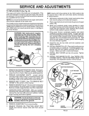
...the shear bolts: 1. Remove the two (2) screws securing belt cover to any service or adjustments: 1. If impeller does not turn when auger control lever is engaged, check to see "TO CONTROL SNOW DISCHARGE" in STOP position. 2. Remove safety ignition key. 3. Install 1/4-20 locknuts and tighten securely. Connect spark plug wire to spark plug. 1/4-20 LOCKNUT 1/4-20 x 1-5/8 CAPSCREW / SHEAR BOLT IMPELLER HUB IMPELLER SHAFT 1/4-20 x 2 SHOULDER / SHEAR BOLT WARNING: To avoid serious injury, never operate your snow thrower. 4. Disengage all controls and move throttle control to...
...the shear bolts: 1. Remove the two (2) screws securing belt cover to any service or adjustments: 1. If impeller does not turn when auger control lever is engaged, check to see "TO CONTROL SNOW DISCHARGE" in STOP position. 2. Remove safety ignition key. 3. Install 1/4-20 locknuts and tighten securely. Connect spark plug wire to spark plug. 1/4-20 LOCKNUT 1/4-20 x 1-5/8 CAPSCREW / SHEAR BOLT IMPELLER HUB IMPELLER SHAFT 1/4-20 x 2 SHOULDER / SHEAR BOLT WARNING: To avoid serious injury, never operate your snow thrower. 4. Disengage all controls and move throttle control to...
User Manual
Page 17
... auger belt around pulleys. 17 BELT KEEPER TRACTION DRIVE BELT ENGINE PULLEY IDLER ARM SQUARE HOLE CLUTCHING IDLER ARM BRACKET FLAT WASHER LOCKWASHER BOLT AUGER BELT AUGER PULLEY BOLT LOCK WASHER FRAME AUGER HOUSING FIG. 23 lbs. REMOVE ENGINE PULLEY - torque). Make sure belt is recommended that the belt(s) be replaced at the same time. INSTALL BELT COVER and two (2) screws. HANDLES 1. Remove bolt, lockwasher and flat washer securing pulley to the snow thrower. WARNING: As the last bolt is important that both the auger and traction drive belt...
... auger belt around pulleys. 17 BELT KEEPER TRACTION DRIVE BELT ENGINE PULLEY IDLER ARM SQUARE HOLE CLUTCHING IDLER ARM BRACKET FLAT WASHER LOCKWASHER BOLT AUGER BELT AUGER PULLEY BOLT LOCK WASHER FRAME AUGER HOUSING FIG. 23 lbs. REMOVE ENGINE PULLEY - torque). Make sure belt is recommended that the belt(s) be replaced at the same time. INSTALL BELT COVER and two (2) screws. HANDLES 1. Remove bolt, lockwasher and flat washer securing pulley to the snow thrower. WARNING: As the last bolt is important that both the auger and traction drive belt...
User Manual
Page 18
... suspected carburetor problems, take your snow thrower with the engine governor, which leads to cool before painting. Do not use the innermost hole in the Service and Adjustments section of time, clean it thoroughly, remove all rusted or chipped paint surfaces; Start the engine and let it from wheel hub and insert pin into cylinder. 3. WARNING: Never store the snow thrower with new spark plug. 5. Run engine at altitudes up all dirt, grease...
... suspected carburetor problems, take your snow thrower with the engine governor, which leads to cool before painting. Do not use the innermost hole in the Service and Adjustments section of time, clean it thoroughly, remove all rusted or chipped paint surfaces; Start the engine and let it from wheel hub and insert pin into cylinder. 3. WARNING: Never store the snow thrower with new spark plug. 5. Run engine at altitudes up all dirt, grease...
User Manual
Page 19
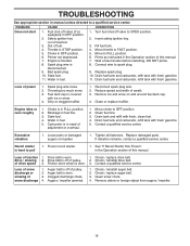
... / reinstall auger belt. 2. TROUBLESHOOTING See appropriate section in manual unless directed to FAST position. 5. Move throttle to a qualified service center. Prime as instructed in need of traction 1. Throwing too much snow. 3. Engine idles or runs roughly 1. Drain tank and refill with fresh gasoline. Replace damaged parts. Frozen recoil starter. 1. Friction drive wheel is not inserted. 3. Check / replace auger belt. 3. Safety ignition key is worn. 3. Choke in FULL position. 2. Spark plug wire is worn. 3. Dirty or clogged muffler. 1. Reduce speed and...
... / reinstall auger belt. 2. TROUBLESHOOTING See appropriate section in manual unless directed to FAST position. 5. Move throttle to a qualified service center. Prime as instructed in need of traction 1. Throwing too much snow. 3. Engine idles or runs roughly 1. Drain tank and refill with fresh gasoline. Replace damaged parts. Frozen recoil starter. 1. Friction drive wheel is not inserted. 3. Check / replace auger belt. 3. Safety ignition key is worn. 3. Choke in FULL position. 2. Spark plug wire is worn. 3. Dirty or clogged muffler. 1. Reduce speed and...

User Manual
Page 21
... 174688 Housing, Gearbox, RH 42 174698 Seal, Oil 43 174701 Bushing, Flange, 1" 44 178879 Key, Square 1/4 x 1/4 x 7/8 45 174659 Gear, Worm 46 174657 Shaft, Auger 47 174687 Housing, Gearbox, LH 48 175321X479 Impeller Assembly 49 74780426 Screw, Hex Head 1/4-20 x 1-5/8 50 175311 Gasket, Gearbox 51 7836M Pin, Roll 3/16 x 1-1/8 NOTE: All component dimensions given in U.S. inches 1 inch = 25.4 mm 21 NO. MODEL NUMBER P8527ESA AUGER HOUSING / IMPELLER ASSEMBLY KEY PART...
... 174688 Housing, Gearbox, RH 42 174698 Seal, Oil 43 174701 Bushing, Flange, 1" 44 178879 Key, Square 1/4 x 1/4 x 7/8 45 174659 Gear, Worm 46 174657 Shaft, Auger 47 174687 Housing, Gearbox, LH 48 175321X479 Impeller Assembly 49 74780426 Screw, Hex Head 1/4-20 x 1-5/8 50 175311 Gasket, Gearbox 51 7836M Pin, Roll 3/16 x 1-1/8 NOTE: All component dimensions given in U.S. inches 1 inch = 25.4 mm 21 NO. MODEL NUMBER P8527ESA AUGER HOUSING / IMPELLER ASSEMBLY KEY PART...
User Manual
Page 27
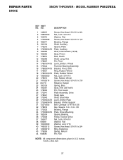
REPAIR PARTS DRIVE SNOW THROWER - MODEL NUMBER P8527ESA KEY PART NO. inches 1 inch = 25.4 mm 27 DESCRIPTION 1 146315 Screw, Hex Head 5/16-18 x 3/4 2 73800500 Nut, Lock 5/16-18 3 155415 Washer, Flat 4 17490508 Screw, Hex Head 5/16-18 x 1/2 5 180017 Bearing, Flange 6 180134 Shaft, Auxiliary 7 179270 Spacer, Plate 8 179269X479 Plate, Auxiliary 9 180082 Gear, Intermediate (12/58) 10 180065 Gear, Pinion 11 178812 Rod, Clutch 12 180066 Shaft, Long, Hex 13 178807 Pin, Pivot 14 178619X479 Lever, Shifter...
REPAIR PARTS DRIVE SNOW THROWER - MODEL NUMBER P8527ESA KEY PART NO. inches 1 inch = 25.4 mm 27 DESCRIPTION 1 146315 Screw, Hex Head 5/16-18 x 3/4 2 73800500 Nut, Lock 5/16-18 3 155415 Washer, Flat 4 17490508 Screw, Hex Head 5/16-18 x 1/2 5 180017 Bearing, Flange 6 180134 Shaft, Auxiliary 7 179270 Spacer, Plate 8 179269X479 Plate, Auxiliary 9 180082 Gear, Intermediate (12/58) 10 180065 Gear, Pinion 11 178812 Rod, Clutch 12 180066 Shaft, Long, Hex 13 178807 Pin, Pivot 14 178619X479 Lever, Shifter...

User Manual
Page 31
... 7 155798 8 155800 9 181039 10 183730 11 183907 12 183905 - - 185143 - - 185148 DESCRIPTION Decal, Danger Decal, Poulan, 8.5 HP/27" Decal, Danger, Deflector Decal, Danger Decal, Poulan Decal, Instruction Decal, Traction Lever Decal, Auger Lever Decal, Speed Control Decal, Remote Deflector Decal, LH Trigger Decal, RH Trigger Owner's Manual (English) Owner's Manual (French) NOTE: All component dimensions given in U.S. inches 1 inch = 25.4 mm 31 NO. MODEL NUMBER P8527ESA KEY PART NO. REPAIR PARTS WHEELS / DECALS SNOW THROWER -
... 7 155798 8 155800 9 181039 10 183730 11 183907 12 183905 - - 185143 - - 185148 DESCRIPTION Decal, Danger Decal, Poulan, 8.5 HP/27" Decal, Danger, Deflector Decal, Danger Decal, Poulan Decal, Instruction Decal, Traction Lever Decal, Auger Lever Decal, Speed Control Decal, Remote Deflector Decal, LH Trigger Decal, RH Trigger Owner's Manual (English) Owner's Manual (French) NOTE: All component dimensions given in U.S. inches 1 inch = 25.4 mm 31 NO. MODEL NUMBER P8527ESA KEY PART NO. REPAIR PARTS WHEELS / DECALS SNOW THROWER -

User Manual
Page 32
... consumer purchaser, we find to be paid by Electrolux Home Products. 3. This Warranty does not apply to any power equipment unit or attachment are belts, shear pins, normal wear, normal adjustments, standard hardware and normal maintenance. 6. Outdoor Products Customer Service Dept. 250 Bobby Jones Expressway Augusta, GA 30909 USA giving the complete mfg. Some areas do not allow the limitation...
... consumer purchaser, we find to be paid by Electrolux Home Products. 3. This Warranty does not apply to any power equipment unit or attachment are belts, shear pins, normal wear, normal adjustments, standard hardware and normal maintenance. 6. Outdoor Products Customer Service Dept. 250 Bobby Jones Expressway Augusta, GA 30909 USA giving the complete mfg. Some areas do not allow the limitation...


