
User Manual
Page 1
ica * ...Y4T6 4 Do 0-1(111) Os tff OWNER'S MANUAL MODEL NO. HDR500F 5 HP 17 inch Tiller Assembly • Operation • Customer Responsibilities • Service and Adjustments • Storage • Troubleshooting • Repair Parts For Parts and Service, contact our authorized distributor: call 1-800-849-1297 For Technical Assistance: call 1-800-829-5886 Poulan 163661 11.20.97 TR PRINTED IN U.S.A.
ica * ...Y4T6 4 Do 0-1(111) Os tff OWNER'S MANUAL MODEL NO. HDR500F 5 HP 17 inch Tiller Assembly • Operation • Customer Responsibilities • Service and Adjustments • Storage • Troubleshooting • Repair Parts For Parts and Service, contact our authorized distributor: call 1-800-849-1297 For Technical Assistance: call 1-800-829-5886 Poulan 163661 11.20.97 TR PRINTED IN U.S.A.
User Manual
Page 2
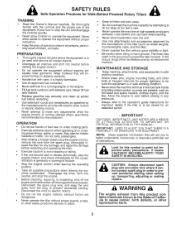
... units with electric drive motors or electric starting motors. • Never attempt to make certain all clutches and shift into neutral, and stop the engine (motor), remove the wire from the plug to operate the equipment. Never allow children to prevent accidental starting the engine (motor). • Do not operate the equipment without proper guards, plates, or other safety protective devices in safe working condition. • Check shear pins, engine mounting bolts, and...
... units with electric drive motors or electric starting motors. • Never attempt to make certain all clutches and shift into neutral, and stop the engine (motor), remove the wire from the plug to operate the equipment. Never allow children to prevent accidental starting the engine (motor). • Do not operate the equipment without proper guards, plates, or other safety protective devices in safe working condition. • Check shear pins, engine mounting bolts, and...
User Manual
Page 3
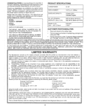
... products used for parts or labor incurred in . (206cc) GASOLINE CAPACITY: 3 Quarts (2.8L) Unleaded Regular OIL (API-SF/SG/SH): (CAPACITY: 20 oz. /0.6L) SAE 30 (Above 32FI0°C) SAE 5W-30 (Below 32°F/0°C) SERIAL NUMBER SPARK PLUG : (GAP: .030"/0.76mm) Champion J19LM DATE OF PURCHASE THE MODEL AND SERIAL NUMBERS WILL BE FOUND ON THE MODEL PLATE ATTACHED TO THE TOP OF THE TRANSMISSION...
... products used for parts or labor incurred in . (206cc) GASOLINE CAPACITY: 3 Quarts (2.8L) Unleaded Regular OIL (API-SF/SG/SH): (CAPACITY: 20 oz. /0.6L) SAE 30 (Above 32FI0°C) SAE 5W-30 (Below 32°F/0°C) SERIAL NUMBER SPARK PLUG : (GAP: .030"/0.76mm) Champion J19LM DATE OF PURCHASE THE MODEL AND SERIAL NUMBERS WILL BE FOUND ON THE MODEL PLATE ATTACHED TO THE TOP OF THE TRANSMISSION...
User Manual
Page 4
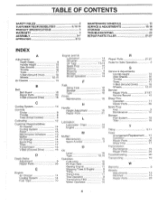
... Engine M Muffler: Maintenance Spark Arrester 0 Oil: Level Type Operation: Cultivating Fill Fuel Tank Starting Engine Stopping Tines & Engine Tilling Tilling Hints Tine Operation Transporting Tiller Winter Operation 14 10 10,14 15 11 9 19 14 10 19 10 15 15 21 13 14 15 3 10 10,14 12 10 11 9 9 11 9 10 14 R Repair Parts Rules for Safe Operation 21-27 2 S Service & Adjustments: Handle Height Side Shields Throttle Tines V-Belt (Ground Drive) Wheels Service: Repair Parts Service Record Shear Pins: Operation Repair Parts Spark Plug: Gap Maintenance Storage: Fuel System Tiller...
... Engine M Muffler: Maintenance Spark Arrester 0 Oil: Level Type Operation: Cultivating Fill Fuel Tank Starting Engine Stopping Tines & Engine Tilling Tilling Hints Tine Operation Transporting Tiller Winter Operation 14 10 10,14 15 11 9 19 14 10 19 10 15 15 21 13 14 15 3 10 10,14 12 10 11 9 9 11 9 10 14 R Repair Parts Rules for Safe Operation 21-27 2 S Service & Adjustments: Handle Height Side Shields Throttle Tines V-Belt (Ground Drive) Wheels Service: Repair Parts Service Record Shear Pins: Operation Repair Parts Spark Plug: Gap Maintenance Storage: Fuel System Tiller...
User Manual
Page 5
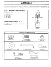
... securely. Use the correct tools as necessary to insure proper tightness. Standard wrench sizes are in the operating position (standing behind tiller handles). OPERATOR'S POSITION FIG. 1 CONTENTS OF HARDWARE PACK (2) Handle Locks IIIIIIIIIII 1) Carriage Bolt 3/8-16 UNC x 1 Grade 5 (1) Center Locknut 3/8-16 UNC 0 0 (1) Flat Washer 13/32 x 1 x 11 Gauge (1) Handle Lock Lever (1) Hairpin Clip iiTi (1) Pivot Bolt 3/8-16 UNC Grade 5 c) Extra Shear Pins & Clips 5 ASSEMBLY • Your new tiller has been assembled at the...
... securely. Use the correct tools as necessary to insure proper tightness. Standard wrench sizes are in the operating position (standing behind tiller handles). OPERATOR'S POSITION FIG. 1 CONTENTS OF HARDWARE PACK (2) Handle Locks IIIIIIIIIII 1) Carriage Bolt 3/8-16 UNC x 1 Grade 5 (1) Center Locknut 3/8-16 UNC 0 0 (1) Flat Washer 13/32 x 1 x 11 Gauge (1) Handle Lock Lever (1) Hairpin Clip iiTi (1) Pivot Bolt 3/8-16 UNC Grade 5 c) Extra Shear Pins & Clips 5 ASSEMBLY • Your new tiller has been assembled at the...

User Manual
Page 6
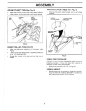
... SLOT HANDLE LOCK FLAT WASHER HANDLE LOCK LEVER CARRIAGE BOLT 11 PIVOT BOLT FIG. 3 HANDLE BASE LOCKNUTS 6 FIG. 5 IMPORTANT: WHEN UNPACKING AND ASSEMBLING TILLER, BE CAREFUL NOT TO STRETCH OR KINK CABLES. • While holding handle assembly, cut cable ties securing handle assembly to hold lever in place. • Insert second handle lock (with some resistance. Insert rear carriage bolt first, with teeth facing outward) in lowest position will allow for easier adjustment...
... SLOT HANDLE LOCK FLAT WASHER HANDLE LOCK LEVER CARRIAGE BOLT 11 PIVOT BOLT FIG. 3 HANDLE BASE LOCKNUTS 6 FIG. 5 IMPORTANT: WHEN UNPACKING AND ASSEMBLING TILLER, BE CAREFUL NOT TO STRETCH OR KINK CABLES. • While holding handle assembly, cut cable ties securing handle assembly to hold lever in place. • Insert second handle lock (with some resistance. Insert rear carriage bolt first, with teeth facing outward) in lowest position will allow for easier adjustment...
User Manual
Page 7
... and pull tiller out of carton. HANDLE HEIGHT • Handle height may be adjusted to secure. END OF CLUTCH CABLE CONTROL BAR BRACKET H -"\ CONTROL BAR BRACKET FIG. 6 REMOVE TILLER FROM CRATE • Make sure shift lever indicator is important for shipping purposes. Correct and equal tire pressure is in the Service and Adjustments section of this manual). 7 Separate cardboard cover from leveling shield. • Rotate tiller handle to 20 PSI (1.4 kg/cm2). ASSEMBLY...
... and pull tiller out of carton. HANDLE HEIGHT • Handle height may be adjusted to secure. END OF CLUTCH CABLE CONTROL BAR BRACKET H -"\ CONTROL BAR BRACKET FIG. 6 REMOVE TILLER FROM CRATE • Make sure shift lever indicator is important for shipping purposes. Correct and equal tire pressure is in the Service and Adjustments section of this manual). 7 Separate cardboard cover from leveling shield. • Rotate tiller handle to 20 PSI (1.4 kg/cm2). ASSEMBLY...

User Manual
Page 8
... shift transmission gears. LEVELING SHIELD - Used when starting a cold engine. 8 Compare the illustrations with your Tiller or in literature supplied with the location of the American National Standards Institute. These symbols may appear on your tiller to familiarize yourself with the product. RECOIL STARTER HANDLE - FNRA F STOP RUN STOP O TILLING FORWARD NEUTRAL REVERSE CAUTION ENGINE ENGINE FAST SLOW CHOKE FUEL OIL OR WARNING ON OFF SHIFT LEVER THROTTLE CONTROL 0 0 RECOIL STARTER HANDLE CHOKE CONTROL DRIVE CONTROL BAR...
... shift transmission gears. LEVELING SHIELD - Used when starting a cold engine. 8 Compare the illustrations with your Tiller or in literature supplied with the location of the American National Standards Institute. These symbols may appear on your tiller to familiarize yourself with the product. RECOIL STARTER HANDLE - FNRA F STOP RUN STOP O TILLING FORWARD NEUTRAL REVERSE CAUTION ENGINE ENGINE FAST SLOW CHOKE FUEL OIL OR WARNING ON OFF SHIFT LEVER THROTTLE CONTROL 0 0 RECOIL STARTER HANDLE CHOKE CONTROL DRIVE CONTROL BAR...
User Manual
Page 10
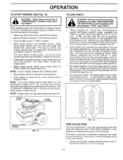
... fuel tank. Loosen nut "A" in your turn . • Move throttle control to lock in this manual. CHECK ENGINE OIL LEVEL (See Fig. 12) • The engine in slot and nut "B". Disconnect spark plug wire. BEFORE STARTING ENGINE IMPORTANT: BE VERY CAREFUL NOT TO ALLOW DIRT TO ENTER THE ENGINE WHEN CHECKING OR ADDING OIL OR FUEL. WARNING: Experience indicates that the shields can be emptied before storage of this manual for transporting the tiller. Drain the gas tank, start tiller...
... fuel tank. Loosen nut "A" in your turn . • Move throttle control to lock in this manual. CHECK ENGINE OIL LEVEL (See Fig. 12) • The engine in slot and nut "B". Disconnect spark plug wire. BEFORE STARTING ENGINE IMPORTANT: BE VERY CAREFUL NOT TO ALLOW DIRT TO ENTER THE ENGINE WHEN CHECKING OR ADDING OIL OR FUEL. WARNING: Experience indicates that the shields can be emptied before storage of this manual for transporting the tiller. Drain the gas tank, start tiller...
User Manual
Page 11
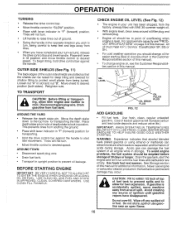
... shear pin(s) break, replace only with shear pins (See "TINE REPLACEMENT' in the Service and Adjustments section of sod or hard ground, apply upward pressure on handle or lower the depth stake. /2 3 RECOIL STARTER HANDLE FIG. 13 FIG. 14 TINE SHEAR PINS The tine assemblies on handle. OPERATION TO START ENGINE (See Fig. 13) A CAUTION: Keep drive control bar in "DISENGAGED" position when starting engine for best engine performance. Pull rope out slowly until engine reaches start of compression cycle (rope will...
... shear pin(s) break, replace only with shear pins (See "TINE REPLACEMENT' in the Service and Adjustments section of sod or hard ground, apply upward pressure on handle or lower the depth stake. /2 3 RECOIL STARTER HANDLE FIG. 13 FIG. 14 TINE SHEAR PINS The tine assemblies on handle. OPERATION TO START ENGINE (See Fig. 13) A CAUTION: Keep drive control bar in "DISENGAGED" position when starting engine for best engine performance. Pull rope out slowly until engine reaches start of compression cycle (rope will...

User Manual
Page 13
CUSTOMER RESPONSIBILITIES MAINTENANCE SCHEDULE FILL IN DATES AS YOU COMPLETE REGULAR SERVICE 4, co co co C-.2) ' J 'R- ,z. 4O -2'
CUSTOMER RESPONSIBILITIES MAINTENANCE SCHEDULE FILL IN DATES AS YOU COMPLETE REGULAR SERVICE 4, co co co C-.2) ' J 'R- ,z. 4O -2'
User Manual
Page 14
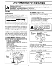
... brush. • Remove blower housing and clean as contact may cause deterioration of all grass, dirt, and debris. Add SAE 30 motor oil or equivalent. ENGINE LUBRICATION Use only high quality detergent oil rated with oil. Select the oil's SAE viscosity grade according to clean or dry cartridge. Check the crankcase oil level before performing any maintenance (except carburetor adjustment) to prevent accidental starting of engine. Do not allow dirt to clean cartridge. AIR CLEAN ER SCREW COVER AIR...
... brush. • Remove blower housing and clean as contact may cause deterioration of all grass, dirt, and debris. Add SAE 30 motor oil or equivalent. ENGINE LUBRICATION Use only high quality detergent oil rated with oil. Select the oil's SAE viscosity grade according to clean or dry cartridge. Check the crankcase oil level before performing any maintenance (except carburetor adjustment) to prevent accidental starting of engine. Do not allow dirt to clean cartridge. AIR CLEAN ER SCREW COVER AIR...
User Manual
Page 15
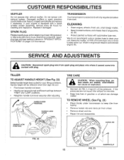
SPARK PLUG Replace spark plugs at different settings between "HIGH" and "LOW" positions. • Retighten handle lock lever securely after every 50 hours of this manual. CLEANING • Clean engine, wheels, finish, etc. Water in engine can result in "PRODUCT SPECIFICATIONS" on page 3 of use, whichever comes first. If tire pressures are seated, overinflation can damage rubber. If your engine is equipped with automotive type wax. TRANSMISSION Your transmission is shown in a shortened engine life. SERVICE AND...
SPARK PLUG Replace spark plugs at different settings between "HIGH" and "LOW" positions. • Retighten handle lock lever securely after every 50 hours of this manual. CLEANING • Clean engine, wheels, finish, etc. Water in engine can result in "PRODUCT SPECIFICATIONS" on page 3 of use, whichever comes first. If tire pressures are seated, overinflation can damage rubber. If your engine is equipped with automotive type wax. TRANSMISSION Your transmission is shown in a shortened engine life. SERVICE AND...

User Manual
Page 17
.... SERVICE AND ADJUSTMENTS TO REMOVE BELT GUARD (See Fig. 27) NOTE: For ease of belt guard (located behind wheel). • Pull belt guard out and away from unit. • Replace belt guard by slipping from left wheel and remove belt guard as described in groove of transmission pulley and into engine pulley. NUT "C" ENGINE PULLEY BELT GUIDE "A" BELT GUIDE "B" CABLE CLIP SCREW DRIVE CONTROL CABLE 0 NUT "D" IDLER PULLEY TRANSMISSION PULLEY FIG. 28 17 LESS TENSION EXTENSION SPRING 5/8" MORE TENSION BELT MUST BE IN GROOVE ON TOP OF IDLER PULLEY. Pull wheel out from tiller...
.... SERVICE AND ADJUSTMENTS TO REMOVE BELT GUARD (See Fig. 27) NOTE: For ease of belt guard (located behind wheel). • Pull belt guard out and away from unit. • Replace belt guard by slipping from left wheel and remove belt guard as described in groove of transmission pulley and into engine pulley. NUT "C" ENGINE PULLEY BELT GUIDE "A" BELT GUIDE "B" CABLE CLIP SCREW DRIVE CONTROL CABLE 0 NUT "D" IDLER PULLEY TRANSMISSION PULLEY FIG. 28 17 LESS TENSION EXTENSION SPRING 5/8" MORE TENSION BELT MUST BE IN GROOVE ON TOP OF IDLER PULLEY. Pull wheel out from tiller...
User Manual
Page 18
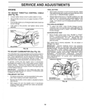
... drive control bar in "DISENGAGED" position. • With throttle control lever in "SLOW" position, turn idle needle valve in (clockwise) until engine begins to die then turn . SERVICE AND ADJUSTMENTS ENGINE TO ADJUST THROTTLE CONTROL CABLE (See Fig. 29) • Loosen cable clamp screw to allow to warm for differences in fuel, temperature, altitude or load. High speed stop while adjusting idle speed adjusting screw to obtain 1750 RPM. FINAL SETTING • Start engine and allow cable to move. • Move throttle control lever on upper handle to adjust...
... drive control bar in "DISENGAGED" position. • With throttle control lever in "SLOW" position, turn idle needle valve in (clockwise) until engine begins to die then turn . SERVICE AND ADJUSTMENTS ENGINE TO ADJUST THROTTLE CONTROL CABLE (See Fig. 29) • Loosen cable clamp screw to allow to warm for differences in fuel, temperature, altitude or load. High speed stop while adjusting idle speed adjusting screw to obtain 1750 RPM. FINAL SETTING • Start engine and allow cable to move. • Move throttle control lever on upper handle to adjust...
User Manual
Page 19
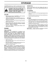
... oil. • Replace with clean oil. (See "ENGINE" in the Service and Adjustments section of oil through spark plug hole into cylinder. • Pull starter handle slowly several times to gasoline in the fuel tank or permanent damage may reach an open flame or spark. Do not use engine or carburetor cleaner products in fuel tank or storage container. ACIDIC GAS CAN DAMAGE THE FUEL SYSTEM OF AN ENGINE WHILE IN STORAGE. • Drain the fuel tank. • Start...
... oil. • Replace with clean oil. (See "ENGINE" in the Service and Adjustments section of oil through spark plug hole into cylinder. • Pull starter handle slowly several times to gasoline in the fuel tank or permanent damage may reach an open flame or spark. Do not use engine or carburetor cleaner products in fuel tank or storage container. ACIDIC GAS CAN DAMAGE THE FUEL SYSTEM OF AN ENGINE WHILE IN STORAGE. • Drain the fuel tank. • Start...
User Manual
Page 20
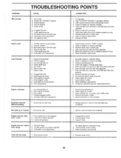
...2. Dirty engine air screen. 3. Check oil level/change spark plug. 5. Carburetor out of fuel. 2. Clean or replace air cleaner cartridge. 5. Throttle control not set properly. 2. Dirty air cleaner. 3. Dirty engine air screen. 11. Drain fuel tank and refill with fresh. Drain fuel tank and carburetor, and refill tank with fresh gasoline. 7. Remove and clean muffler. 5. Adjust carburetor to start 1. Engine runs but labors when tilling 1, Tilling too deep. 2. Engage drive control, 2. Inspect V-belt. Make necessary adjustments. Shear pin...
...2. Dirty engine air screen. 3. Check oil level/change spark plug. 5. Carburetor out of fuel. 2. Clean or replace air cleaner cartridge. 5. Throttle control not set properly. 2. Dirty air cleaner. 3. Dirty engine air screen. 11. Drain fuel tank and refill with fresh. Drain fuel tank and carburetor, and refill tank with fresh gasoline. 7. Remove and clean muffler. 5. Adjust carburetor to start 1. Engine runs but labors when tilling 1, Tilling too deep. 2. Engage drive control, 2. Inspect V-belt. Make necessary adjustments. Shear pin...

User Manual
Page 21
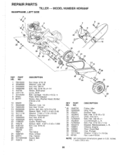
MODEL NUMBER HDR500F HANDLE ASSEMBLY 2 4 5 25 24 22 26 6 26 28 22 27 15 21 17 17 KEY PART NO. NO. inches. 1 inch = 25.4 mm 21 REPAIR PARTS TILLER - - NO. 14 159232 15 145821 17 102604X 18 150696 21 159227 22 150744 24 73731000 25 127012X 26 146480 27 10040500 28 73800500 DESCRIPTION Cable, Clutch Bracket, Clutch Cable Grip, Bar Control Bolt, Pivot Bar, Control Grip, Handle Nut, Keps #10-24 UNC Control, Throttle Grommet...
MODEL NUMBER HDR500F HANDLE ASSEMBLY 2 4 5 25 24 22 26 6 26 28 22 27 15 21 17 17 KEY PART NO. NO. inches. 1 inch = 25.4 mm 21 REPAIR PARTS TILLER - - NO. 14 159232 15 145821 17 102604X 18 150696 21 159227 22 150744 24 73731000 25 127012X 26 146480 27 10040500 28 73800500 DESCRIPTION Cable, Clutch Bracket, Clutch Cable Grip, Bar Control Bolt, Pivot Bar, Control Grip, Handle Nut, Keps #10-24 UNC Control, Throttle Grommet...
User Manual
Page 22
...-18 Washer, Lock 3/8 Nut, Hex 3/8-16 Bolt, Hex 5/16-18 x 4-1/4 Screw, Shift Lever Lever, Shift Bolt, Carriage 1/4-20 x 1/2 Gr. 5 Plate, Shift Indicator Screw, Hex, Washer Head, Slotted #10-24 x 1/2 Clip Washer, Lock 1/4 Nut, Hex 1/4-20 Screw, Set, Hex 5/16-18 x 3/8 Spacer, Split 0.327 x 0.42 x 2.68 Washer 11/32 x 11/16 x 16 Ga. inches. 1 inch = 25.4 mm 22 Sheave, Transmission Nut, Hex 5/16-18 Ring, Retainer Guard, Pinch Point Spacer...
...-18 Washer, Lock 3/8 Nut, Hex 3/8-16 Bolt, Hex 5/16-18 x 4-1/4 Screw, Shift Lever Lever, Shift Bolt, Carriage 1/4-20 x 1/2 Gr. 5 Plate, Shift Indicator Screw, Hex, Washer Head, Slotted #10-24 x 1/2 Clip Washer, Lock 1/4 Nut, Hex 1/4-20 Screw, Set, Hex 5/16-18 x 3/8 Spacer, Split 0.327 x 0.42 x 2.68 Washer 11/32 x 11/16 x 16 Ga. inches. 1 inch = 25.4 mm 22 Sheave, Transmission Nut, Hex 5/16-18 Ring, Retainer Guard, Pinch Point Spacer...

User Manual
Page 24
.... 21 and 22) Gear, Reverse Idler Bearing, Needle Shaft, Reverse Idler Washer, Lock 7/16 Nut, Hex 7/16-20 Bearing, Shaft, Ground Drive L.H. NO. MODEL NUMBER HDR500F TRANSMISSION 3 1 2 6 5 1 35 12 \4. 0 14 1110 16 4 25) 2, 24 9 5 18 7 23 21 22 19 29 30 24 -- ,! w/Bearing (Includes Key No. 8) Shaft, Tine Chain, Roller #50-50 Pitch Screw 1/4-20 x 1/2 Nut, Hex 5/16-18 Kit, Bearing, Tine Shaft Grease, Plastilube #1 NOTE: All...
.... 21 and 22) Gear, Reverse Idler Bearing, Needle Shaft, Reverse Idler Washer, Lock 7/16 Nut, Hex 7/16-20 Bearing, Shaft, Ground Drive L.H. NO. MODEL NUMBER HDR500F TRANSMISSION 3 1 2 6 5 1 35 12 \4. 0 14 1110 16 4 25) 2, 24 9 5 18 7 23 21 22 19 29 30 24 -- ,! w/Bearing (Includes Key No. 8) Shaft, Tine Chain, Roller #50-50 Pitch Screw 1/4-20 x 1/2 Nut, Hex 5/16-18 Kit, Bearing, Tine Shaft Grease, Plastilube #1 NOTE: All...


