
User Manual
Page 1
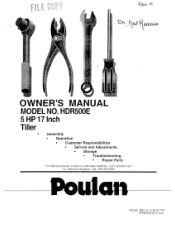
coo itali4i1Lra,006 OWNER'S MANUAL MODEL NO. HDR500E 5 HP 17 Inch Tiller Assembly • Operation • Customer Responsibilities • Service and Adjustments • Storage • Troubleshooting • Repair Parts For Parts and Service, contact our authorized distributor: call 1-800-849-1297 For Technical Assistance: call 1-800-829-5886 156335 Rev. 2 6.30.97 TR PRINTED IN U.S.A.
coo itali4i1Lra,006 OWNER'S MANUAL MODEL NO. HDR500E 5 HP 17 Inch Tiller Assembly • Operation • Customer Responsibilities • Service and Adjustments • Storage • Troubleshooting • Repair Parts For Parts and Service, contact our authorized distributor: call 1-800-849-1297 For Technical Assistance: call 1-800-829-5886 156335 Rev. 2 6.30.97 TR PRINTED IN U.S.A.
User Manual
Page 2
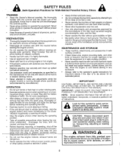
...engine or hot engine. • Fill fuel tank outdoors with extreme care. Disengage the tines, shift into neutral before restarting and operating the tiller. • Exercise caution to avoid slipping or falling. • If the unit should start to cause cancer, birth defects, or other... safety protective devices in the ground and propel the tiller forward. Never fill fuel tank indoors. • Replace gasoline cap securely and clean up , transporting, adjusting or making repairs. SAFETY RULES ...
...engine or hot engine. • Fill fuel tank outdoors with extreme care. Disengage the tines, shift into neutral before restarting and operating the tiller. • Exercise caution to avoid slipping or falling. • If the unit should start to cause cancer, birth defects, or other... safety protective devices in the ground and propel the tiller forward. Never fill fuel tank indoors. • Replace gasoline cap securely and clean up , transporting, adjusting or making repairs. SAFETY RULES ...
User Manual
Page 3
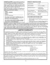
...TO THE SAME TIME PERIODS STATED HEREIN FOR OUR EXPRESSED WARRANTIES. This Warranty gives you specific legal rights, and you . MODEL NUMBER HDR500E PRODUCT SPECIFICATIONS HORSEPOWER: 5.0 HP DISPLACEMENT: 12.57 cu. in replacing parts, any products used for the movement of any power equipment... For a period of two (2) years from this Warranty are the responsibility of the product. 5. The Warranty period for and using your tiller. • Follow instructions under this Owner's Manual. Box 1687 Orangeburg, SC 29116 USA American Yard Products 1040 Jayson Court Mississauga, Ontario ...
...TO THE SAME TIME PERIODS STATED HEREIN FOR OUR EXPRESSED WARRANTIES. This Warranty gives you specific legal rights, and you . MODEL NUMBER HDR500E PRODUCT SPECIFICATIONS HORSEPOWER: 5.0 HP DISPLACEMENT: 12.57 cu. in replacing parts, any products used for the movement of any power equipment... For a period of two (2) years from this Warranty are the responsibility of the product. 5. The Warranty period for and using your tiller. • Follow instructions under this Owner's Manual. Box 1687 Orangeburg, SC 29116 USA American Yard Products 1040 Jayson Court Mississauga, Ontario ...

User Manual
Page 4
... Chart Engine M Muffler: Maintenance Spark Arrester 0 Oil: Level Type Operation: Cultivating Fill Fuel Tank Starting Engine Stopping Tines & Engine Tilling Hints Tine Operation Transporting Tiller Winter Operation 14 10 10,14 15 11 9 19 14 10 19 10 15 15 21 13 14 15 3 10 10,14 12 10 11...Side Shields Throttle Tines V-Belt (Ground Drive) Wheels Service: Repair Parts Service Record Shear Pins: Operation Repair Parts Spark Plug: Gap Maintenance Storage: Fuel System Tiller 21-27 2 15 10 18 17 16 12,15 21-27 13 11 26 3 15 19 19 T Tilling Tines: Arrangement/Replacement Operation Repair Parts ...
... Chart Engine M Muffler: Maintenance Spark Arrester 0 Oil: Level Type Operation: Cultivating Fill Fuel Tank Starting Engine Stopping Tines & Engine Tilling Hints Tine Operation Transporting Tiller Winter Operation 14 10 10,14 15 11 9 19 14 10 19 10 15 15 21 13 14 15 3 10 10,14 12 10 11...Side Shields Throttle Tines V-Belt (Ground Drive) Wheels Service: Repair Parts Service Record Shear Pins: Operation Repair Parts Spark Plug: Gap Maintenance Storage: Fuel System Tiller 21-27 2 15 10 18 17 16 12,15 21-27 13 11 26 3 15 19 19 T Tilling Tines: Arrangement/Replacement Operation Repair Parts ...
User Manual
Page 5
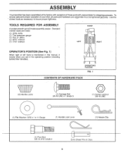
TOOLS REQUIRED FOR ASSEMBLY A socket wrench set will make assembly easier. ASSEMBLY Your new tiller has been assembled at the factory with exception of your tiller, all parts and hardware you are in the operating position (standing behind tiller handles). Standard wrench sizes are listed. (1) Utility knife (1) Tire pressure gauge (1) Pair of pliers (1) 9/16...
TOOLS REQUIRED FOR ASSEMBLY A socket wrench set will make assembly easier. ASSEMBLY Your new tiller has been assembled at the factory with exception of your tiller, all parts and hardware you are in the operating position (standing behind tiller handles). Standard wrench sizes are listed. (1) Utility knife (1) Tire pressure gauge (1) Pair of pliers (1) 9/16...

User Manual
Page 6
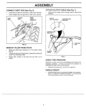
... lay side carton wall down. • Remove packing material from carton. Insert handle lock lever through handle base and gearcase. SIDE OF TILLER O O HANDLE ASSEMBLY GEARCASE NOTCH HANDLE LOCK • Grasp handle assembly. Insert rear carriage bolt first, with teeth inward) in front .... Let handle assembly rest on L.H. ASSEMBLY UNPACKING CARTON (See Fig. 2) CAUTION: Be careful of exposed staples when handling or disposing of tiller and loosely assemble locknut (See Fig. 5). Insert pivot bolt in the slot of the handle base (just inside of plate and tighten....
... lay side carton wall down. • Remove packing material from carton. Insert handle lock lever through handle base and gearcase. SIDE OF TILLER O O HANDLE ASSEMBLY GEARCASE NOTCH HANDLE LOCK • Grasp handle assembly. Insert rear carriage bolt first, with teeth inward) in front .... Let handle assembly rest on L.H. ASSEMBLY UNPACKING CARTON (See Fig. 2) CAUTION: Be careful of exposed staples when handling or disposing of tiller and loosely assemble locknut (See Fig. 5). Insert pivot bolt in the slot of the handle base (just inside of plate and tighten....
User Manual
Page 7
... (See "TO ADJUST HANDLE HEIGHT" in "N" position (See Fig. 6) • Tilt tiller forward by lifting handle. END OF CLUTCH CABLE CONTROL BAR BRACKET r N CONTROL BAR BRACKET FIG. 6 REMOVE TILLER FROM CRATE • Make sure shift lever indicator is important for shipping purposes. CONTROL BAR ...for best tilling performance. • Reduce tire pressure to the right and pull tiller out of clutclicable through hole of this manual). 7 Separate cardboard cover from leveling shield. • Rotate tiller handle to 20 PSI (1.4 kg/cm2). SHIFT ROD HAIRPIN CLIP SHIFT LEVER INDICATOR ...
... (See "TO ADJUST HANDLE HEIGHT" in "N" position (See Fig. 6) • Tilt tiller forward by lifting handle. END OF CLUTCH CABLE CONTROL BAR BRACKET r N CONTROL BAR BRACKET FIG. 6 REMOVE TILLER FROM CRATE • Make sure shift lever indicator is important for shipping purposes. CONTROL BAR ...for best tilling performance. • Reduce tire pressure to the right and pull tiller out of clutclicable through hole of this manual). 7 Separate cardboard cover from leveling shield. • Rotate tiller handle to 20 PSI (1.4 kg/cm2). SHIFT ROD HAIRPIN CLIP SHIFT LEVER INDICATOR ...

User Manual
Page 8
... DRIVE CONTROL BAR ii I DEPTH STAKE 0 o O V O LEVELING SHIELD OUTER SIDE SHIELD FIG. 8 MEETS ANSI SAFETY REQUIREMENTS Our tillers conform to familiarize yourself with the product. Used to control engine speed. ----DRIVE-CONTROL OAR Used to shift transmission gears. Adjustable to start... the engine. OPERATION KNOW YOUR TILLER READ THIS OWNER'S MANUAL AND SAFETY RULES BEFORE OPERATING YOUR TILLER. THROTTLE CONTROL - Levels tilled soil. CHOKE CONTROL - Compare the illustrations with your Tiller or in literature supplied with the I6Cation of the...
... DRIVE CONTROL BAR ii I DEPTH STAKE 0 o O V O LEVELING SHIELD OUTER SIDE SHIELD FIG. 8 MEETS ANSI SAFETY REQUIREMENTS Our tillers conform to familiarize yourself with the product. Used to control engine speed. ----DRIVE-CONTROL OAR Used to shift transmission gears. Adjustable to start... the engine. OPERATION KNOW YOUR TILLER READ THIS OWNER'S MANUAL AND SAFETY RULES BEFORE OPERATING YOUR TILLER. THROTTLE CONTROL - Levels tilled soil. CHOKE CONTROL - Compare the illustrations with your Tiller or in literature supplied with the I6Cation of the...

User Manual
Page 9
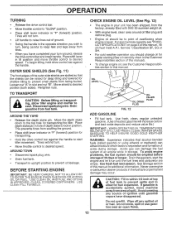
...start tilling movement. WITH WHEEL DRIVE • Always release drive control bar before moving shift lever into the eyes, which can be set at any tiller can result in foreign objects thrown into another position. • Tine movement is achieved by moving shift lever to "SLOW" position. Move throttle ...in severe eye damage. Place depth stake pin in hole of any desired speed, depending on how fast or slow you more easily transport your tiller and while tilling. OPERATION WEAR YOUR FORESIGHT IS BETTER THAN NO SIGHT The operation of depth stake to lock in position. • Place ...
...start tilling movement. WITH WHEEL DRIVE • Always release drive control bar before moving shift lever into the eyes, which can be set at any tiller can result in foreign objects thrown into another position. • Tine movement is achieved by moving shift lever to "SLOW" position. Move throttle ...in severe eye damage. Place depth stake pin in hole of any desired speed, depending on how fast or slow you more easily transport your tiller and while tilling. OPERATION WEAR YOUR FORESIGHT IS BETTER THAN NO SIGHT The operation of depth stake to lock in position. • Place ...
User Manual
Page 10
... nuts. Engine oil should change engine oil, see "PRODUCT SPECIFICATIONS" on page 3 of fuel tank to prevent spills and to allow tiller engine and muffler to cool. USE CLEAN FILL FUNNELS. Wipe off any source of overflowing when engine is accidentally spilled, move throttle control...or SH. • For cold weather operation you wish to turn . • Move throttle control to desired speed. Drain the gas tank, start tiller movement. AROUND TOWN • Disconnect spark plug wire. • Drain fuel tank. • Transport in your turn . • Lift handle to ...
... nuts. Engine oil should change engine oil, see "PRODUCT SPECIFICATIONS" on page 3 of fuel tank to prevent spills and to allow tiller engine and muffler to cool. USE CLEAN FILL FUNNELS. Wipe off any source of overflowing when engine is accidentally spilled, move throttle control...or SH. • For cold weather operation you wish to turn . • Move throttle control to desired speed. Drain the gas tank, start tiller movement. AROUND TOWN • Disconnect spark plug wire. • Drain fuel tank. • Transport in your turn . • Lift handle to ...
User Manual
Page 11
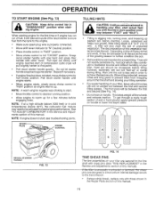
... choking to start. • Move throttle control to desired running position. • Allow engine to excessive bounce and difficult handling of your tiller, start , see troubleshooting points. NOTE: If engine does not start actual field use with those shown in the Repair Parts section of this... When engine starts, slowly move fuel from wrapping around the tine shaft and slowing your tilling operation. • For easier handling of your tiller are important for a few minutes before planting. The third pass will "ball-up for proper tilling. Grasp recoil starter handle with one hand...
... choking to start. • Move throttle control to desired running position. • Allow engine to excessive bounce and difficult handling of your tiller, start , see troubleshooting points. NOTE: If engine does not start actual field use with those shown in the Repair Parts section of this... When engine starts, slowly move fuel from wrapping around the tine shaft and slowing your tilling operation. • For easier handling of your tiller are important for a few minutes before planting. The third pass will "ball-up for proper tilling. Grasp recoil starter handle with one hand...

User Manual
Page 12
... INNER VIEW OF TIRE HAIRPIN CLIP FIG. 15 ADJUST WHEELS FOR CULTIVATING (See Figs. 16 and 17) • Place blocks under right hand side of tiller and remove hairpin clip and clevis pin from the plants. OPERATION CULTIVATING Cultivating is 1" to 3" (2.5-7.5 cm). At the same time, breaking up the upper layer...
... INNER VIEW OF TIRE HAIRPIN CLIP FIG. 15 ADJUST WHEELS FOR CULTIVATING (See Figs. 16 and 17) • Place blocks under right hand side of tiller and remove hairpin clip and clevis pin from the plants. OPERATION CULTIVATING Cultivating is 1" to 3" (2.5-7.5 cm). At the same time, breaking up the upper layer...
User Manual
Page 13
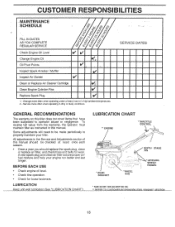
CUSTOMER RESPONSIBILITIES -MAINTENANCE SCHEDULE FILL IN DATES AS YOU COMPLETE REGULAR SERVICE 4/ . co co 'Z ' 'CZ' 0 O T ,,z, ,Z. 0 4/ -1
CUSTOMER RESPONSIBILITIES -MAINTENANCE SCHEDULE FILL IN DATES AS YOU COMPLETE REGULAR SERVICE 4/ . co co 'Z ' 'CZ' 0 O T ,,z, ,Z. 0 4/ -1
User Manual
Page 14
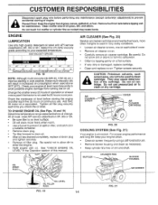
...each time you check the oil level. Be careful not to allow dirt or debris to fall into carburetor. • Man by tapping gently on tiller, and catch oil in cold weather, these multi-viscosity oils will drain more often if engine is not used to your engine clean. •...CHANGE FIG. 18 NOTE: Although multi-viscosity oils (5W-30, OW-30, etc.) improve starting in a suitable container. • Remove drain plug. • Tip tiller forward to enter the engine. • Refill engine with API service classification SF, SG or SH. Add SAE 30 motor oil or equivalent. Be careful...
...each time you check the oil level. Be careful not to allow dirt or debris to fall into carburetor. • Man by tapping gently on tiller, and catch oil in cold weather, these multi-viscosity oils will drain more often if engine is not used to your engine clean. •...CHANGE FIG. 18 NOTE: Although multi-viscosity oils (5W-30, OW-30, etc.) improve starting in a suitable container. • Remove drain plug. • Tip tiller forward to enter the engine. • Refill engine with API service classification SF, SG or SH. Add SAE 30 motor oil or equivalent. Be careful...
User Manual
Page 15
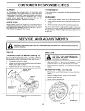
...and reassemble. Handle height will only req4Ve lubrication if serviced. TO REMOVE WHEEL (See Fig. 23) • Place blocks under transmission to keep tiller from tipping. • Remove hairpin clip and clevis pin from spark plug and place wire where it cannot come into soil. • First ... to keep water out. Keep finished surfaces and wheels free of tire pressure. HANDLE (HIGH POSITION) HANDLE (LOW POSITION) HANDLE LOCK LEVER - TILLER TO ADJUST HANDLE HEIGHT (See Fig. 22) Select handle height best suited for cleaning and inspection. CLEVIS PIN FIG. 22 HAIRPIN CLIP FIG. ...
...and reassemble. Handle height will only req4Ve lubrication if serviced. TO REMOVE WHEEL (See Fig. 23) • Place blocks under transmission to keep tiller from tipping. • Remove hairpin clip and clevis pin from spark plug and place wire where it cannot come into soil. • First ... to keep water out. Keep finished surfaces and wheels free of tire pressure. HANDLE (HIGH POSITION) HANDLE (LOW POSITION) HANDLE LOCK LEVER - TILLER TO ADJUST HANDLE HEIGHT (See Fig. 22) Select handle height best suited for cleaning and inspection. CLEVIS PIN FIG. 22 HAIRPIN CLIP FIG. ...

User Manual
Page 16
... TINE SHARP EDGE HAIRPIN CLIP SHARP EDGE SHARP EDGE SHEAR PIN SHARP EDGES 0 SHEAR PIN SHARP EDGE FIG. 26 16 A badly worn tine causes your tiller to the transmission. TRANSMISSION - Sharpened tine edges will rotate rearward from above. Wear gloves or other protection when handling tines. SERVICE AND ADJUSTMENTS TINE REPLACEMENT...
... TINE SHARP EDGE HAIRPIN CLIP SHARP EDGE SHARP EDGE SHEAR PIN SHARP EDGES 0 SHEAR PIN SHARP EDGE FIG. 26 16 A badly worn tine causes your tiller to the transmission. TRANSMISSION - Sharpened tine edges will rotate rearward from above. Wear gloves or other protection when handling tines. SERVICE AND ADJUSTMENTS TINE REPLACEMENT...

User Manual
Page 17
...; HAIRPIN CLIP AND CLEVIS PIN FIG. 27 TO REPLACE GROUND DRIVE BELT (See Figs. 27 and 28) • Move left wheel. Pull wheel out from tiller about 5/8 inch (16 mm) stretch when drive control bar is engaged. • Tighten cable clip screw securely.
...; HAIRPIN CLIP AND CLEVIS PIN FIG. 27 TO REPLACE GROUND DRIVE BELT (See Figs. 27 and 28) • Move left wheel. Pull wheel out from tiller about 5/8 inch (16 mm) stretch when drive control bar is engaged. • Tighten cable clip screw securely.
User Manual
Page 19
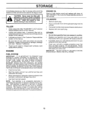
...ENGINE" in minimizing the formation of this manual). Do not drain the gas tank and carburetor if using fuel stabilizer. IMPORTANT: NEVER COVER TILLER WHILE ENGINE AND EXHAUST AREAS ARE STILL WARM. 19 Allow the engine to rust. sand lightly before storing in fuel tank or storage ...or permanent damage may reach an open flame or spark. Immediately prepare your unit to reach the carburetor. A CAUTION: Never store the tiller with a suitable protective cover that all rusted or chipped paint surfaces; Inspect moving parts for storage at least 10 minutes after adding ...
...ENGINE" in minimizing the formation of this manual). Do not drain the gas tank and carburetor if using fuel stabilizer. IMPORTANT: NEVER COVER TILLER WHILE ENGINE AND EXHAUST AREAS ARE STILL WARM. 19 Allow the engine to rust. sand lightly before storing in fuel tank or storage ...or permanent damage may reach an open flame or spark. Immediately prepare your unit to reach the carburetor. A CAUTION: Never store the tiller with a suitable protective cover that all rusted or chipped paint surfaces; Inspect moving parts for storage at least 10 minutes after adding ...
User Manual
Page 20
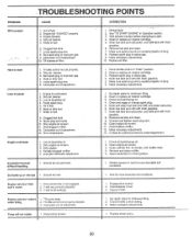
.... 5. Wait several minutes before attempting to start . 4. Spark plug wire loose. 10. Drain and clean fuel tank and refill, and clean carburetor. 6. Engine runs but tiller won't move 1. Clean cylinder fins, air screen, and muffler area. 4. Bad spark plug or improper gap. 4. Adjust carburetor to richer position. 1. Make necessary adjustments. Low...
.... 5. Wait several minutes before attempting to start . 4. Spark plug wire loose. 10. Drain and clean fuel tank and refill, and clean carburetor. 6. Engine runs but tiller won't move 1. Clean cylinder fins, air screen, and muffler area. 4. Bad spark plug or improper gap. 4. Adjust carburetor to richer position. 1. Make necessary adjustments. Low...

User Manual
Page 21
... Washer 13/32 x 1 x 11 Ga. 12 109228X Lever, Lock, Handle 13 150217 Handle ,o 1 12 18 KEY PART NO. inches. 1 inch = 25.4 mm 21 MODEL NUMBER HDR500E HANDLE ASSEMBLY 2 3 4 5 25 24 22 26 6 C; 26 28 22 27 15 21 17 14 13 17 KEY PART NO. NO. 14 145820 15 145821 17..., Handle Nut, Keps #10-24 UNC Control, Throttle Grommet, Handle Washer, Lock 5/16 Locknut 5/16-18 NOTE: All component dimensions given in U.S. NO. REPAIR PARTS TILLER - -
... Washer 13/32 x 1 x 11 Ga. 12 109228X Lever, Lock, Handle 13 150217 Handle ,o 1 12 18 KEY PART NO. inches. 1 inch = 25.4 mm 21 MODEL NUMBER HDR500E HANDLE ASSEMBLY 2 3 4 5 25 24 22 26 6 C; 26 28 22 27 15 21 17 14 13 17 KEY PART NO. NO. 14 145820 15 145821 17..., Handle Nut, Keps #10-24 UNC Control, Throttle Grommet, Handle Washer, Lock 5/16 Locknut 5/16-18 NOTE: All component dimensions given in U.S. NO. REPAIR PARTS TILLER - -


