
User Manual
Page 1
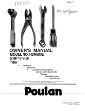
HDR500E 5 HP 17 Inch Tiller Assembly • Operation • Customer Responsibilities • Service and Adjustments • Storage • Troubleshooting • Repair Parts For Parts and Service, contact our authorized distributor: call 1-800-849-1297 For Technical Assistance: call 1-800-829-5886 156335 Rev. 2 6.30.97 TR PRINTED IN U.S.A. coo itali4i1Lra,006 OWNER'S MANUAL MODEL NO.
HDR500E 5 HP 17 Inch Tiller Assembly • Operation • Customer Responsibilities • Service and Adjustments • Storage • Troubleshooting • Repair Parts For Parts and Service, contact our authorized distributor: call 1-800-849-1297 For Technical Assistance: call 1-800-829-5886 156335 Rev. 2 6.30.97 TR PRINTED IN U.S.A. coo itali4i1Lra,006 OWNER'S MANUAL MODEL NO.
User Manual
Page 2
.... Be thoroughly familiar with the controls and the proper use care when backing. • Never allow adults to operate the equipment without wearing adequate outer garments. Stay alert for Walk-Behind Powered Rotary Tillers TRAINING Read the Owner's Manual carefully. Vibration is in safe working condition. • Never store the machine with electric drive motors or electric starting motors. • Never attempt to...
.... Be thoroughly familiar with the controls and the proper use care when backing. • Never allow adults to operate the equipment without wearing adequate outer garments. Stay alert for Walk-Behind Powered Rotary Tillers TRAINING Read the Owner's Manual carefully. Vibration is in safe working condition. • Never store the machine with electric drive motors or electric starting motors. • Never attempt to...
User Manual
Page 3
.... The instructions will repair or replace, at our option, without charge for the movement of a new tiller. MODEL NUMBER HDR500E PRODUCT SPECIFICATIONS HORSEPOWER: 5.0 HP DISPLACEMENT: 12.57 cu. SAE 30 (Above 32°F/0°C) (CAPACITY: 20 oz. /0.6L) SAE 5W-30 (Below 32°F/0°C) SERIAL NUMBER SPARK PLUG : (GAP: .030"/0.76mm) Champion RJ19LM DATE OF PURCHASE THE MODEL AND SERIAL NUMBERS WILL BE FOUND ON THE MODEL PLATE ATTACHED TO...
.... The instructions will repair or replace, at our option, without charge for the movement of a new tiller. MODEL NUMBER HDR500E PRODUCT SPECIFICATIONS HORSEPOWER: 5.0 HP DISPLACEMENT: 12.57 cu. SAE 30 (Above 32°F/0°C) (CAPACITY: 20 oz. /0.6L) SAE 5W-30 (Below 32°F/0°C) SERIAL NUMBER SPARK PLUG : (GAP: .030"/0.76mm) Champion RJ19LM DATE OF PURCHASE THE MODEL AND SERIAL NUMBERS WILL BE FOUND ON THE MODEL PLATE ATTACHED TO...

User Manual
Page 4
... Parts L Lubrication: Lubrication Chart Engine M Muffler: Maintenance Spark Arrester 0 Oil: Level Type Operation: Cultivating Fill Fuel Tank Starting Engine Stopping Tines & Engine Tilling Hints Tine Operation Transporting Tiller Winter Operation 14 10 10,14 15 11 9 19 14 10 19 10 15 15 21 13 14 15 3 10 10,14 12 10 11 9 11 9 10 14 R Repair Parts Rules for Safe Operation S Service & Adjustments: Handle Height Side Shields Throttle Tines V-Belt (Ground Drive) Wheels Service: Repair Parts Service Record Shear Pins: Operation Repair Parts Spark Plug: Gap Maintenance Storage: Fuel System Tiller...
... Parts L Lubrication: Lubrication Chart Engine M Muffler: Maintenance Spark Arrester 0 Oil: Level Type Operation: Cultivating Fill Fuel Tank Starting Engine Stopping Tines & Engine Tilling Hints Tine Operation Transporting Tiller Winter Operation 14 10 10,14 15 11 9 19 14 10 19 10 15 15 21 13 14 15 3 10 10,14 12 10 11 9 11 9 10 14 R Repair Parts Rules for Safe Operation S Service & Adjustments: Handle Height Side Shields Throttle Tines V-Belt (Ground Drive) Wheels Service: Repair Parts Service Record Shear Pins: Operation Repair Parts Spark Plug: Gap Maintenance Storage: Fuel System Tiller...
User Manual
Page 5
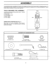
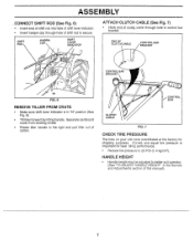
... UNC 0 0 (1) Flat Washer 13/32 x 1 x 11 Gauge (1) Handle Lock Lever (1) Hairpin Clip 1 11H (1) Pivot Bolt 3/8-16 UNC Grade 5 Extra Shear Pins & Clips 5 To ensure safe and proper operation of your tiller, all parts and hardware you are listed. (1) Utility knife (1) Tire pressure gauge (1) Pair of those parts left hand is mentioned in the operating position (standing behind tiller handles). ASSEMBLY Your new tiller has been assembled at the factory with exception of...
... UNC 0 0 (1) Flat Washer 13/32 x 1 x 11 Gauge (1) Handle Lock Lever (1) Hairpin Clip 1 11H (1) Pivot Bolt 3/8-16 UNC Grade 5 Extra Shear Pins & Clips 5 To ensure safe and proper operation of your tiller, all parts and hardware you are listed. (1) Utility knife (1) Tire pressure gauge (1) Pair of those parts left hand is mentioned in the operating position (standing behind tiller handles). ASSEMBLY Your new tiller has been assembled at the factory with exception of...

User Manual
Page 6
... cartoning material. Screw in place. IMPORTANT: WHEN UNPACKING AND ASSEMBLING TILLER, BE CAREFUL NOT TO STRETCH OR KINK CABLES. • While holding handle assembly, cut cable ties securing handle assembly to hold lever in handle lock lever just enough to top frame. Tighten nut on carriage bolt bolt so handle moves with bolt head on threaded end of handle lock to remove tiller from handle assembly. Hold in front part of carton. • Slowly ease handle assembly up " position. Place...
... cartoning material. Screw in place. IMPORTANT: WHEN UNPACKING AND ASSEMBLING TILLER, BE CAREFUL NOT TO STRETCH OR KINK CABLES. • While holding handle assembly, cut cable ties securing handle assembly to hold lever in handle lock lever just enough to top frame. Tighten nut on carriage bolt bolt so handle moves with bolt head on threaded end of handle lock to remove tiller from handle assembly. Hold in front part of carton. • Slowly ease handle assembly up " position. Place...
User Manual
Page 7
... HAIRPIN CLIP SHIFT LEVER INDICATOR ATTACH CLUTCH CABLE (See.Fig. 7) • Hook end,of clutclicable through hole of shift rod to better suit operator. (See "TO ADJUST HANDLE HEIGHT" in control bar bracket. Separate cardboard cover from leveling shield. • Rotate tiller handle to 20 PSI (1.4 kg/cm2). HANDLE HEIGHT • Handle height may be adjusted to secure. Correct and equal tire pressure is in "N" position (See Fig...
... HAIRPIN CLIP SHIFT LEVER INDICATOR ATTACH CLUTCH CABLE (See.Fig. 7) • Hook end,of clutclicable through hole of shift rod to better suit operator. (See "TO ADJUST HANDLE HEIGHT" in control bar bracket. Separate cardboard cover from leveling shield. • Rotate tiller handle to 20 PSI (1.4 kg/cm2). HANDLE HEIGHT • Handle height may be adjusted to secure. Correct and equal tire pressure is in "N" position (See Fig...

User Manual
Page 8
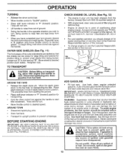
.... Levels tilled soil. Used to shift transmission gears. SHIFT LEVER - Compare the illustrations with your Tiller or in literature supplied with the I6Cation of the American National Standards Institute. OPERATION KNOW YOUR TILLER READ THIS OWNER'S MANUAL AND SAFETY RULES BEFORE OPERATING YOUR TILLER. F FNR TILLING FORWARD NEUTRAL REVERSE CAUTION ENGINE OR WARNING ON ENGINE OFF FAST SLOW CHOKE FUEL OIL I RUN STOP O SHIFT LEVER THROTTLE CONTROL O O RECOIL STARTER HANDLE CHOKE CONTROL DRIVE CONTROL BAR ii I DEPTH STAKE 0 o O V O LEVELING...
.... Levels tilled soil. Used to shift transmission gears. SHIFT LEVER - Compare the illustrations with your Tiller or in literature supplied with the I6Cation of the American National Standards Institute. OPERATION KNOW YOUR TILLER READ THIS OWNER'S MANUAL AND SAFETY RULES BEFORE OPERATING YOUR TILLER. F FNR TILLING FORWARD NEUTRAL REVERSE CAUTION ENGINE OR WARNING ON ENGINE OFF FAST SLOW CHOKE FUEL OIL I RUN STOP O SHIFT LEVER THROTTLE CONTROL O O RECOIL STARTER HANDLE CHOKE CONTROL DRIVE CONTROL BAR ii I DEPTH STAKE 0 o O V O LEVELING...
User Manual
Page 10
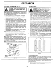
... lever indicator in position. USE CLEAN FILL FUNNELS. Acidic gas can attract moisture which leads to separation and formation of an engine while in your turn , being buried. Drain the gas tank, start tiller movement. If gasoline is level. To begin tilling, hold drive control bar against the handle to the top hole for additional information. Retighten nuts. Move the depth stake down to start the engine and let it run...
... lever indicator in position. USE CLEAN FILL FUNNELS. Acidic gas can attract moisture which leads to separation and formation of an engine while in your turn , being buried. Drain the gas tank, start tiller movement. If gasoline is level. To begin tilling, hold drive control bar against the handle to the top hole for additional information. Retighten nuts. Move the depth stake down to start the engine and let it run...
User Manual
Page 11
... need to be adjusted for proper tilling. pins are secured to the tine shaft with those shown in the Repair Parts section of this point). • Pull recoil starter handle quickly. When starting engine. however, extremely wet soil will pull slightly harder at this manual). Pull rope out slowly until engine reaches start . • Move throttle control to desired running position. • Allow engine to warm up for the first time or if engine...
... need to be adjusted for proper tilling. pins are secured to the tine shaft with those shown in the Repair Parts section of this point). • Pull recoil starter handle quickly. When starting engine. however, extremely wet soil will pull slightly harder at this manual). Pull rope out slowly until engine reaches start . • Move throttle control to desired running position. • Allow engine to warm up for the first time or if engine...
User Manual
Page 13
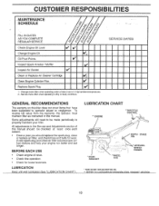
co co 'Z ' 'CZ' 0 O T ,,z, ,Z. 0 4/ -1 CUSTOMER RESPONSIBILITIES -MAINTENANCE SCHEDULE FILL IN DATES AS YOU COMPLETE REGULAR SERVICE 4/ .
co co 'Z ' 'CZ' 0 O T ,,z, ,Z. 0 4/ -1 CUSTOMER RESPONSIBILITIES -MAINTENANCE SCHEDULE FILL IN DATES AS YOU COMPLETE REGULAR SERVICE 4/ .
User Manual
Page 14
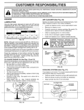
...; Clean air screen frequently using a stiff-bristled brush. • Remove blower housing and clean as kerosene, are not to prevent accidental starting of dirt and chaff. Add SAE 30 motor oil or equivalent. All oil must meet API service classification SF, SG or SH. • Be sure tiller is not used for maintenance. MUFFLER CYLINDER FINS BLOWER HOUSING OIL DRAIN PLUG AIR SCREEN OIL LEVEL OIL FILLER PLUG FIG. 19 14 II FIG. 21 CUSTOMER RESPONSIBILITIES Disconnect spark plug wire before oil change. Tighten screws...
...; Clean air screen frequently using a stiff-bristled brush. • Remove blower housing and clean as kerosene, are not to prevent accidental starting of dirt and chaff. Add SAE 30 motor oil or equivalent. All oil must meet API service classification SF, SG or SH. • Be sure tiller is not used for maintenance. MUFFLER CYLINDER FINS BLOWER HOUSING OIL DRAIN PLUG AIR SCREEN OIL LEVEL OIL FILLER PLUG FIG. 19 14 II FIG. 21 CUSTOMER RESPONSIBILITIES Disconnect spark plug wire before oil change. Tighten screws...
User Manual
Page 15
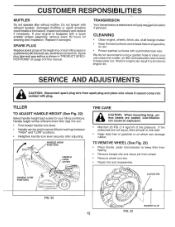
... replace if necessary. Spark plug type and gap setting is sealed and will only req4Ve lubrication if serviced. We do not recommend using a garden hose to clean your tilling conditions. Protect painted surfaces with exhaust system. Keep finished surfaces and wheels free of this manual. Handle height will pull to keep water out. SPARK PLUG Replace spark plugs at different settings between "HIGH" and "LOW" positions. • Retighten handle lock lever securely after adjusting. HANDLE (HIGH POSITION) HANDLE (LOW POSITION) HANDLE LOCK LEVER - CLEVIS PIN...
... replace if necessary. Spark plug type and gap setting is sealed and will only req4Ve lubrication if serviced. We do not recommend using a garden hose to clean your tilling conditions. Protect painted surfaces with exhaust system. Keep finished surfaces and wheels free of this manual. Handle height will pull to keep water out. SPARK PLUG Replace spark plugs at different settings between "HIGH" and "LOW" positions. • Retighten handle lock lever securely after adjusting. HANDLE (HIGH POSITION) HANDLE (LOW POSITION) HANDLE LOCK LEVER - CLEVIS PIN...

User Manual
Page 17
... drive control bar is engaged. • Tighten cable clip screw securely. SERVICE AND ADJUSTMENTS TO REMOVE BELT GUARD (See Fig. 27) NOTE: For ease of removal, remove hairpin clip and clevis pin from engine pulley first. • Place new belt in groove of belt guard (located behind wheel). • Pull belt guard out and away from unit. • Replace belt guard by slipping from left wheel and remove belt guard as described in "ENGAGED" position. NUT "D' IDLER PULLEY TRANSMISSION PULLEY FIG. 28 17 LESS TENSION EXTENSION SPRING...
... drive control bar is engaged. • Tighten cable clip screw securely. SERVICE AND ADJUSTMENTS TO REMOVE BELT GUARD (See Fig. 27) NOTE: For ease of removal, remove hairpin clip and clevis pin from engine pulley first. • Place new belt in groove of belt guard (located behind wheel). • Pull belt guard out and away from unit. • Replace belt guard by slipping from left wheel and remove belt guard as described in "ENGAGED" position. NUT "D' IDLER PULLEY TRANSMISSION PULLEY FIG. 28 17 LESS TENSION EXTENSION SPRING...
User Manual
Page 18
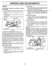
... SETTING • Start engine and allow to warm for differences in (clockwise) decreases the supply of fuel to compensate for five minutes. Repeat test and . THROTTLE LINKAGE THROTTLE STOP 0 IDLE SPEED ADJUSTING SCREW IDLE NEEDLE VALVE FIG. 30 18 SERVICE AND ADJUSTMENTS ENGINE TO ADJUST THROTTLE CONTROL CABLE (See Fig. 29) ---•-to-o-sen-cable-cl-arnirscre-w-to-allowntil to rnove7-----" • Move throttle control lever on upper handle to "FAST" position. • Pull throttle cable out until engine...
... SETTING • Start engine and allow to warm for differences in (clockwise) decreases the supply of fuel to compensate for five minutes. Repeat test and . THROTTLE LINKAGE THROTTLE STOP 0 IDLE SPEED ADJUSTING SCREW IDLE NEEDLE VALVE FIG. 30 18 SERVICE AND ADJUSTMENTS ENGINE TO ADJUST THROTTLE CONTROL CABLE (See Fig. 29) ---•-to-o-sen-cable-cl-arnirscre-w-to-allowntil to rnove7-----" • Move throttle control lever on upper handle to "FAST" position. • Pull throttle cable out until engine...
User Manual
Page 19
... WHICH LEADS TO SEPARATION AND FORMATION OF ACIDS DURING STORAGE. Run engine at the end of oil through spark plug hole into cylinder. • Pull starter handle slowly several times to reach the carburetor. A CAUTION: Never store the tiller with new spark plug. Replace if necessary. • Touch up all nuts, bolts and screws are empty. • Never use plastic. Add stabilizer to rust. Immediately prepare your unit to...
... WHICH LEADS TO SEPARATION AND FORMATION OF ACIDS DURING STORAGE. Run engine at the end of oil through spark plug hole into cylinder. • Pull starter handle slowly several times to reach the carburetor. A CAUTION: Never store the tiller with new spark plug. Replace if necessary. • Touch up all nuts, bolts and screws are empty. • Never use plastic. Add stabilizer to rust. Immediately prepare your unit to...
User Manual
Page 20
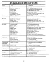
...Throttle control not properly adjusted. 3. Engage drive control. 2. Clogged fuel tank. 7. CORRECTION 1. • Fill fuel tank. 2. Remove fuel tank and clean. 7. Clean and regap or change oil. 2. Drain fuel tank and carburetor, and refill tank with fresh gasoline. 6. Wait for more favorable soil conditions. 1. Replace spark plug or adjust gap. 9. Check oil level/change oil. 4. Partially plugged muffler. 5. Clean engine air screen. 3. Check throttle control setting. 3. Engine not "CHOKED" properly. 3. Oil soaked air filter. 1. Place throttle control in fuel...
...Throttle control not properly adjusted. 3. Engage drive control. 2. Clogged fuel tank. 7. CORRECTION 1. • Fill fuel tank. 2. Remove fuel tank and clean. 7. Clean and regap or change oil. 2. Drain fuel tank and carburetor, and refill tank with fresh gasoline. 6. Wait for more favorable soil conditions. 1. Replace spark plug or adjust gap. 9. Check oil level/change oil. 4. Partially plugged muffler. 5. Clean engine air screen. 3. Check throttle control setting. 3. Engine not "CHOKED" properly. 3. Oil soaked air filter. 1. Place throttle control in fuel...

User Manual
Page 21
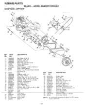
... Lever, Lock, Handle 13 150217 Handle ,o 1 12 18 KEY PART NO. NO. 14 145820 15 145821 17 102604X 18 150696 21 145829 22 150744 24 73731000 25 127012X 26 146480 27 10040500 28 73800500 DESCRIPTION Cable, Clutch Bracket, Clutch Cable Grip, Bar Control Bolt, Pivot Bar, Control Grip, Handle Nut, Keps #10-24 UNC Control, Throttle Grommet, Handle Washer, Lock 5/16 Locknut 5/16-18 NOTE: All component dimensions given in U.S. MODEL NUMBER HDR500E HANDLE ASSEMBLY...
... Lever, Lock, Handle 13 150217 Handle ,o 1 12 18 KEY PART NO. NO. 14 145820 15 145821 17 102604X 18 150696 21 145829 22 150744 24 73731000 25 127012X 26 146480 27 10040500 28 73800500 DESCRIPTION Cable, Clutch Bracket, Clutch Cable Grip, Bar Control Bolt, Pivot Bar, Control Grip, Handle Nut, Keps #10-24 UNC Control, Throttle Grommet, Handle Washer, Lock 5/16 Locknut 5/16-18 NOTE: All component dimensions given in U.S. MODEL NUMBER HDR500E HANDLE ASSEMBLY...
User Manual
Page 22
... 132672 DESCRIPTION Nut, Keps 5/16-18 Washer, Lock 3/8 Nut, Hex 3/8-16 Bolt, Hex 5/16-18 x 4-1/4 Screw, Shift Lever Lever, Shift Bolt, Carriage 1/4-20 x 1/2 Gr. 5 Plate, Shift Indicator Screw, Hex, Washer Head, Slotted #10-24 x 1/2 Clip Washer, Lock 1/4 Nut, Hex 1/4-20 Screw, Set, Hex 5/16-18 x 3/8 Spacer, Split 0.327 x 0.42 x 2.68 Washer 11/32 x 11/16 x 16 Ga. NO. Sheave, Engine Stud, Guard Belt Cap. inches. 1 inch = 25.4 mm 22 H. REPAIR PARTS TILLER - Nt 4 38...
... 132672 DESCRIPTION Nut, Keps 5/16-18 Washer, Lock 3/8 Nut, Hex 3/8-16 Bolt, Hex 5/16-18 x 4-1/4 Screw, Shift Lever Lever, Shift Bolt, Carriage 1/4-20 x 1/2 Gr. 5 Plate, Shift Indicator Screw, Hex, Washer Head, Slotted #10-24 x 1/2 Clip Washer, Lock 1/4 Nut, Hex 1/4-20 Screw, Set, Hex 5/16-18 x 3/8 Spacer, Split 0.327 x 0.42 x 2.68 Washer 11/32 x 11/16 x 16 Ga. NO. Sheave, Engine Stud, Guard Belt Cap. inches. 1 inch = 25.4 mm 22 H. REPAIR PARTS TILLER - Nt 4 38...

User Manual
Page 24
REPAIR PARTS TILLER - - MODEL NUMBER HDR500E TRANSMISSION 3 ! 2 . 15) 6 4 1 35 • 12, \d" 13 15 9 14 111011 16, 9 5 18 7 23 21 22 19 29 30 20 28 31 18 34 27 3 18 40 . 37 39 7 3 36 24. 2 25 24 25 4 42 41 49 44 48 53 25 2)41_, 50 lf
REPAIR PARTS TILLER - - MODEL NUMBER HDR500E TRANSMISSION 3 ! 2 . 15) 6 4 1 35 • 12, \d" 13 15 9 14 111011 16, 9 5 18 7 23 21 22 19 29 30 20 28 31 18 34 27 3 18 40 . 37 39 7 3 36 24. 2 25 24 25 4 42 41 49 44 48 53 25 2)41_, 50 lf


