
User Manual
Page 1
p fo• OWNER'S MANUAL MODEL NO. HDF550M 5 HP 26 Inch Tiller • Assembly • Operation • Maintenance • Service and Adjustments • Storage • Troubleshooting • Repair Parts For Parts and Service, contact our authorized distributor: call 1-800-849-1297 For Technical Assistance: call 1-800-829-5886 Poulan 184860 Rev. 1 05.13.03 TR PRINTED IN U.S.A.
p fo• OWNER'S MANUAL MODEL NO. HDF550M 5 HP 26 Inch Tiller • Assembly • Operation • Maintenance • Service and Adjustments • Storage • Troubleshooting • Repair Parts For Parts and Service, contact our authorized distributor: call 1-800-849-1297 For Technical Assistance: call 1-800-829-5886 Poulan 184860 Rev. 1 05.13.03 TR PRINTED IN U.S.A.
User Manual
Page 2
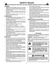
... fuel before starting motors. • Never attempt to better understand, incorporate, or execute a particular set of the equipment. MAINTENANCE AND STORAGE • Keep machine, attachments, and accessories in safe working condition. • Check shear pins, engine mounting bolts, and other safety protective devices in hard ground. A WARNINGa The engine exhaust from the spark plug, thoroughly inspect the tiller for any adjustments while the engine (motor) is highly flammable. • Use...
... fuel before starting motors. • Never attempt to better understand, incorporate, or execute a particular set of the equipment. MAINTENANCE AND STORAGE • Keep machine, attachments, and accessories in safe working condition. • Check shear pins, engine mounting bolts, and other safety protective devices in hard ground. A WARNINGa The engine exhaust from the spark plug, thoroughly inspect the tiller for any adjustments while the engine (motor) is highly flammable. • Use...
User Manual
Page 3
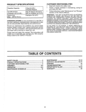
...°F/0°C) Champion RC12YC CONGRATULATIONS on your tiller. • Follow instructions under"Maintenance" and "Storage" sections of a new tiller. Always observe the "SAFETY RULES". IF A SPARK ARRESTER IS USED, IT SHOULD BE MAINTAINED IN EFFECTIVE WORKING ORDER BY THE OPERATOR. FEDERAL LAWS APPLY ON FEDERAL LANDS. TABLE OF CONTENTS SAFETY RULES PRODUCT SPECIFICATIONS CUSTOMER RESPONSIBILITIES ASSEMBLY OPERATION MAINTENANCE SCHEDULE 2 MAINTENANCE 3 SERVICE & ADJUSTMENTS 3 STORAGE 4-5 TROUBLESHOOTING 6-9 REPAIR PARTS-TILLER 10 WARRANTY 10-12...
...°F/0°C) Champion RC12YC CONGRATULATIONS on your tiller. • Follow instructions under"Maintenance" and "Storage" sections of a new tiller. Always observe the "SAFETY RULES". IF A SPARK ARRESTER IS USED, IT SHOULD BE MAINTAINED IN EFFECTIVE WORKING ORDER BY THE OPERATOR. FEDERAL LAWS APPLY ON FEDERAL LANDS. TABLE OF CONTENTS SAFETY RULES PRODUCT SPECIFICATIONS CUSTOMER RESPONSIBILITIES ASSEMBLY OPERATION MAINTENANCE SCHEDULE 2 MAINTENANCE 3 SERVICE & ADJUSTMENTS 3 STORAGE 4-5 TROUBLESHOOTING 6-9 REPAIR PARTS-TILLER 10 WARRANTY 10-12...
User Manual
Page 5
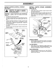
... Service and Adjustments section of this manual). FIG. 2 i 5 HANDLE PANEL LOCK NUT WASHER TILLER HANDLE / GI \ HEX BOLT 5/16-18X1" FLAT WASHER HEX BOLT 5/16-18X3/4" CABLE(S) TILLER HANDLES HANDLE PANEL BOLTS 2 . 0 INSTALL DEPTH STAKE ASSEMBLY (See Fig. 3) • Loosen nut "A". • Insert stake support between engine bracket halves with stake spring down. • Bolt stake support to better handle your tilling conditions (See "TINE ARRANGEMENT" in lower hole of handle. Tighten securely. TINE OPERATION • Check...
... Service and Adjustments section of this manual). FIG. 2 i 5 HANDLE PANEL LOCK NUT WASHER TILLER HANDLE / GI \ HEX BOLT 5/16-18X1" FLAT WASHER HEX BOLT 5/16-18X3/4" CABLE(S) TILLER HANDLES HANDLE PANEL BOLTS 2 . 0 INSTALL DEPTH STAKE ASSEMBLY (See Fig. 3) • Loosen nut "A". • Insert stake support between engine bracket halves with stake spring down. • Bolt stake support to better handle your tilling conditions (See "TINE ARRANGEMENT" in lower hole of handle. Tighten securely. TINE OPERATION • Check...

User Manual
Page 6
... TILLER READ THIS OWNER'S MANUAL AND SAFETY RULES BEFORE OPERATING YOUR TILLER. These symbols may appear on your tiller to start the engine. 6 Learn and understand their meaning. Used when starting a cold engine. RECOIL STARTER HANDLE - THROTTLE CONTROL - Engages tines in forward direction. CHOKE CONTROL - Controls engine speed. F FNRA rILLING FORWARD NEUTRAL REVERSE CAUTION ENGINE OR WARNING ON ENGINE OFF FAST SLOW CHOKE FUEL CIL RUN STOP FORWARD TINE CONTROL REVERSE TINE CONTROL O DEPTH STAKE 0 0 RECOIL STARTER HANDLE O O 0 0 0 O CHOKE CONTROL THROTTLE...
... TILLER READ THIS OWNER'S MANUAL AND SAFETY RULES BEFORE OPERATING YOUR TILLER. These symbols may appear on your tiller to start the engine. 6 Learn and understand their meaning. Used when starting a cold engine. RECOIL STARTER HANDLE - THROTTLE CONTROL - Engages tines in forward direction. CHOKE CONTROL - Controls engine speed. F FNRA rILLING FORWARD NEUTRAL REVERSE CAUTION ENGINE OR WARNING ON ENGINE OFF FAST SLOW CHOKE FUEL CIL RUN STOP FORWARD TINE CONTROL REVERSE TINE CONTROL O DEPTH STAKE 0 0 RECOIL STARTER HANDLE O O 0 0 0 O CHOKE CONTROL THROTTLE...

User Manual
Page 7
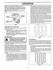
... pin. Change wheel position. We recommend a wide vision safety mask for digging. ment. WHEELS (See Fig. 6) Adjust wheels by removing the hairpin clip and clevis pin. Always wear safety glasses or eye shields before adding fuel and oil or attempting to stop engine. HOW TO USE YOUR TILLER Know how to operate all controls before starting your tiller and while tilling. ENGINE • Move throttle control to "STOP" position. • Never use choke to start engine...
... pin. Change wheel position. We recommend a wide vision safety mask for digging. ment. WHEELS (See Fig. 6) Adjust wheels by removing the hairpin clip and clevis pin. Always wear safety glasses or eye shields before adding fuel and oil or attempting to stop engine. HOW TO USE YOUR TILLER Know how to operate all controls before starting your tiller and while tilling. ENGINE • Move throttle control to "STOP" position. • Never use choke to start engine...

User Manual
Page 8
... fuel. Pull rope out slowly until engine reaches start , move choke control to assure fuel freshness. Replace oil filler plug. • For cold weather operation you should be used within 1/2 inch of top of overflowing. Wipe off any source of compression cycle (rope will pull slightly harder at this manual. • Tilt tiller back on page 3 of this point). • Pull recoil starter handle quickly. Never use gasoline near an open position. • Move choke control...
... fuel. Pull rope out slowly until engine reaches start , move choke control to assure fuel freshness. Replace oil filler plug. • For cold weather operation you should be used within 1/2 inch of top of overflowing. Wipe off any source of compression cycle (rope will pull slightly harder at this manual. • Tilt tiller back on page 3 of this point). • Pull recoil starter handle quickly. Never use gasoline near an open position. • Move choke control...
User Manual
Page 9
... ground, the slower the engine and tine speed needed. SPARK PLUG CHOKE CONTROL THROTTLE CONTROL RECOIL STARTER HANDLE • Soil conditions are important for doing this manual. First, wide turns are accustomed to rotate for shallow tilling when working extremely hard soil or sod. See"TINE OPERATION CHECK" in the Service and Adjustments section of this vegetable matter enriches the soil. At the same time, breaking up the...
... ground, the slower the engine and tine speed needed. SPARK PLUG CHOKE CONTROL THROTTLE CONTROL RECOIL STARTER HANDLE • Soil conditions are important for doing this manual. First, wide turns are accustomed to rotate for shallow tilling when working extremely hard soil or sod. See"TINE OPERATION CHECK" in the Service and Adjustments section of this vegetable matter enriches the soil. At the same time, breaking up the...

User Manual
Page 10
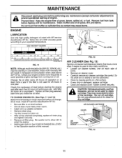
... manual should replace the spark plug, clean or replace air filter, and check tines and belts for loose fasteners. To receive full value from the warranty, operator must maintain tiller as instructed in dirty or dusty conditions. LUBRICATION CHART O TINE CONTROL 0 ENGINE O IDLER ARM ()SAE 30 OR 10W-30 MOTOR OIL °REFER TO MAINTENANCE "ENGINE" SECTION 10 A new spark plug and clean air filter assure proper air-fuel mixture and help your tiller. BEFORE EACH USE • Check engine oil level. • Check tine operation. • Check...
... manual should replace the spark plug, clean or replace air filter, and check tines and belts for loose fasteners. To receive full value from the warranty, operator must maintain tiller as instructed in dirty or dusty conditions. LUBRICATION CHART O TINE CONTROL 0 ENGINE O IDLER ARM ()SAE 30 OR 10W-30 MOTOR OIL °REFER TO MAINTENANCE "ENGINE" SECTION 10 A new spark plug and clean air filter assure proper air-fuel mixture and help your tiller. BEFORE EACH USE • Check engine oil level. • Check tine operation. • Check...
User Manual
Page 11
...! MAINTENANCE A Disconnect spark plug wire before performing any maintenance (except carburetor adjustment) to clean or dry cartridge. Tighten oil filler plug securely each side of continuous use pressurized air to prevent accidental starting of this manual. Do not allow dirt to drain oil. • After oil has drained completely, replace oil drain plug and tighten securely. • Remove oil filler plug. Change the oil after each five (5) hours of cover. • Remove air cleaner cover. • Carefully remove air cleaner cartridge. OIL FILLER PLUG OIL LEVEL FIG. 12 AIR...
...! MAINTENANCE A Disconnect spark plug wire before performing any maintenance (except carburetor adjustment) to clean or dry cartridge. Tighten oil filler plug securely each side of continuous use pressurized air to prevent accidental starting of this manual. Do not allow dirt to drain oil. • After oil has drained completely, replace oil drain plug and tighten securely. • Remove oil filler plug. Change the oil after each five (5) hours of cover. • Remove air cleaner cover. • Carefully remove air cleaner cartridge. OIL FILLER PLUG OIL LEVEL FIG. 12 AIR...
User Manual
Page 12
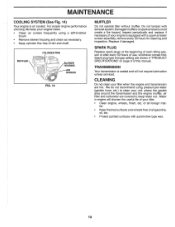
... a spark arrester screen assembly, remove every 50 hours for cleaning and inspection. Replace if damaged. TRANSMISSION Your transmission is air cooled. brush. • Remove blower housing and clean as necessary. • Keep cylinder fins free of this manual. ter. • Keep finished surfaces and wheels free of your engine clean. • Clean air screen frequently using pressurized water (garden hose, etc.) to keep your tiller. • Clean engine, wheels, finish, etc. If your tiller when the engine and transmission are covered to clean your...
... a spark arrester screen assembly, remove every 50 hours for cleaning and inspection. Replace if damaged. TRANSMISSION Your transmission is air cooled. brush. • Remove blower housing and clean as necessary. • Keep cylinder fins free of this manual. ter. • Keep finished surfaces and wheels free of your engine clean. • Clean air screen frequently using pressurized water (garden hose, etc.) to keep your tiller. • Clean engine, wheels, finish, etc. If your tiller when the engine and transmission are covered to clean your...

User Manual
Page 13
... tiller digs into contact with plug. Select handle height best suited for your tilling or cultivating needs. Wear gloves or other protection when handling tines. SERVICE AND ADJUSTMENTS A CAUTION: Disconnect spark plug wire from spark plug and place wire where it cannot come into soil. • If a higher handle height is desired, loosen the four nuts securing handle panel to engine brackets. • Slide handle panel to desired location...
... tiller digs into contact with plug. Select handle height best suited for your tilling or cultivating needs. Wear gloves or other protection when handling tines. SERVICE AND ADJUSTMENTS A CAUTION: Disconnect spark plug wire from spark plug and place wire where it cannot come into soil. • If a higher handle height is desired, loosen the four nuts securing handle panel to engine brackets. • Slide handle panel to desired location...
User Manual
Page 14
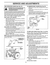
... belt is inside all belt guides and rests on idler pulley. • Beforeinstalling reverse(outside groove of transmission pulley. Pull up on cable to prevent starting while checking tine operation. Be sure slot in bottom of belt guard is under head of tine shield bolt and all belt guides before removing belts. CHECK TINE OPERATION • See "TINE OPERATION CHECK" in this section of manual. TO REMOVE BELT GUARD (See Fig. 20) • Remove two (2) cap nuts and washers from engine pulley...
... belt is inside all belt guides and rests on idler pulley. • Beforeinstalling reverse(outside groove of transmission pulley. Pull up on cable to prevent starting while checking tine operation. Be sure slot in bottom of belt guard is under head of tine shield bolt and all belt guides before removing belts. CHECK TINE OPERATION • See "TINE OPERATION CHECK" in this section of manual. TO REMOVE BELT GUARD (See Fig. 20) • Remove two (2) cap nuts and washers from engine pulley...
User Manual
Page 16
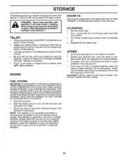
... and cover it run until the fuel lines and carburetor are securely fastened. OTHER • Do not store gasoline from dust and dirt. • Cover your can if your unit with new spark plug. Inspect moving parts for 30 days or more. Run engine at the end of oil through spark plug hole into cylinder. • Pull starter handle slowly several times to distribute oil. • Replace with a suitable protective cover that...
... and cover it run until the fuel lines and carburetor are securely fastened. OTHER • Do not store gasoline from dust and dirt. • Cover your can if your unit with new spark plug. Inspect moving parts for 30 days or more. Run engine at the end of oil through spark plug hole into cylinder. • Pull starter handle slowly several times to distribute oil. • Replace with a suitable protective cover that...
User Manual
Page 17
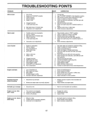
.... 5. Throttle control not set properly. 2. Dirty air cleaner. 3. Loose spark plug wire. 6. Faulty spark plug. 5. Clogged fuel tank. 9. Poor compression. 1. Remove fuel tank and clean. 9. Clean/replace muffler. 12. Partially plugged muffler. 5. Check oil level/change oil. 4. Engage tine control. 2. Inspect V-belt. Carburetor out of adjustment. TROUBLESHOOTING POINTS PROBLEM Will not start . 4. Engine not "CHOKED" properly. 3. Bad spark plug or improper gap. 9. Make sure spark plug wire is off pulley(s). 1. Oil in the Operation section. 3. Set...
.... 5. Throttle control not set properly. 2. Dirty air cleaner. 3. Loose spark plug wire. 6. Faulty spark plug. 5. Clogged fuel tank. 9. Poor compression. 1. Remove fuel tank and clean. 9. Clean/replace muffler. 12. Partially plugged muffler. 5. Check oil level/change oil. 4. Engage tine control. 2. Inspect V-belt. Carburetor out of adjustment. TROUBLESHOOTING POINTS PROBLEM Will not start . 4. Engine not "CHOKED" properly. 3. Bad spark plug or improper gap. 9. Make sure spark plug wire is off pulley(s). 1. Oil in the Operation section. 3. Set...

User Manual
Page 18
..., Handle 16 166377 Handle, R.H. 18 166868 Cable, Control, Tine 19 151229 Lever, Control, Tine 20 154805 Pin, Pivot 21 12000027 Ring, Klip 28 19131312 Washer 13/32 x 13/16 x 12 Ga. 29 12000059 Retaining, Ring 43 180528 Cable Assembly, Reverse 44 181580 Clip 45 73920600 Nut Keps 3/8-24 Unt NOTE: All component dimensions are given in U.S. inches. 1 inch = 25.4 mm 18 MODEL NUMBER HDF55OM HANDLE ASSEMBLY 29...
..., Handle 16 166377 Handle, R.H. 18 166868 Cable, Control, Tine 19 151229 Lever, Control, Tine 20 154805 Pin, Pivot 21 12000027 Ring, Klip 28 19131312 Washer 13/32 x 13/16 x 12 Ga. 29 12000059 Retaining, Ring 43 180528 Cable Assembly, Reverse 44 181580 Clip 45 73920600 Nut Keps 3/8-24 Unt NOTE: All component dimensions are given in U.S. inches. 1 inch = 25.4 mm 18 MODEL NUMBER HDF55OM HANDLE ASSEMBLY 29...
User Manual
Page 19
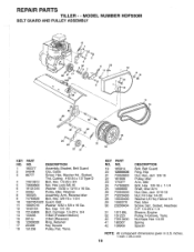
..., Cable 3 86777 Screw, Hex, Washer Hd., Slotted, Thd. KEY PART NO. Nut Keps Hex 1/4-20 Spring Spacer NOTE: All component dimensions given in U.S. i 1.. NO. inches. 1 inch = 25.4 mm 19 v 28 7 „/"ZZ, 8 29 10 11 e, 13 14 15 25 20 a, 1 24 23 21 32 18 KEY PART NO. REPAIR PARTS TILLER - - MODEL NUMBER HDF550M BELT GUARD AND PULLEY ASSEMBLY f---- , --- 1 ....^.... •4.... 11. ...•„%i . ,----- .'ez* , ,4-.....c. -.,_ /4-c-,-,-,NAit4,t. Cutting #10-24 x 1/2 Type D 4 74610812 Bolt...
..., Cable 3 86777 Screw, Hex, Washer Hd., Slotted, Thd. KEY PART NO. Nut Keps Hex 1/4-20 Spring Spacer NOTE: All component dimensions given in U.S. i 1.. NO. inches. 1 inch = 25.4 mm 19 v 28 7 „/"ZZ, 8 29 10 11 e, 13 14 15 25 20 a, 1 24 23 21 32 18 KEY PART NO. REPAIR PARTS TILLER - - MODEL NUMBER HDF550M BELT GUARD AND PULLEY ASSEMBLY f---- , --- 1 ....^.... •4.... 11. ...•„%i . ,----- .'ez* , ,4-.....c. -.,_ /4-c-,-,-,NAit4,t. Cutting #10-24 x 1/2 Type D 4 74610812 Bolt...
User Manual
Page 20
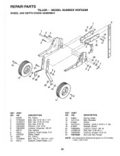
MODEL NUMBER HDF550M WHEEL AND DEPTH STAKE ASSEMBLY 16 17 2 3 2 -- -../,gy ----i!'', 7-,q4f1r!1ilt-ii l e, cs i l %14 6i, - 6 --"- /-• 13 ^ 3 9 7 0 10 0 11 22 0 - REPAIR PARTS TILLER - -
MODEL NUMBER HDF550M WHEEL AND DEPTH STAKE ASSEMBLY 16 17 2 3 2 -- -../,gy ----i!'', 7-,q4f1r!1ilt-ii l e, cs i l %14 6i, - 6 --"- /-• 13 ^ 3 9 7 0 10 0 11 22 0 - REPAIR PARTS TILLER - -

User Manual
Page 22
... KEY PART NO. inches. 1 inch = 25.4 mm 22 MODEL NUMBER HDF550M TRANSMISSION 2 3 3 5 6 I 11 7 1,1 0 14 14 8 14 10 14 12 KEY PART NO. DESCRIPTION 14 9173R Spacer, Split 15 73970500 Nut Lock Hex Fig 16 19091412 Washer 9/32 x 7/8 x 12 Ga. 17 19092016 Washer 9/32 x 1-1/4 x 16 Ga • 18 10040400 Washer, Lock 1/4 19 74610412 Bolt, Hex 1/4-28 x 3/4 Gr. 5 20 Engine, Briggs Model 126402 Order parts from engine manufac- Bracket, Engine, L.H. turer...
... KEY PART NO. inches. 1 inch = 25.4 mm 22 MODEL NUMBER HDF550M TRANSMISSION 2 3 3 5 6 I 11 7 1,1 0 14 14 8 14 10 14 12 KEY PART NO. DESCRIPTION 14 9173R Spacer, Split 15 73970500 Nut Lock Hex Fig 16 19091412 Washer 9/32 x 7/8 x 12 Ga. 17 19092016 Washer 9/32 x 1-1/4 x 16 Ga • 18 10040400 Washer, Lock 1/4 19 74610412 Bolt, Hex 1/4-28 x 3/4 Gr. 5 20 Engine, Briggs Model 126402 Order parts from engine manufac- Bracket, Engine, L.H. turer...
User Manual
Page 24
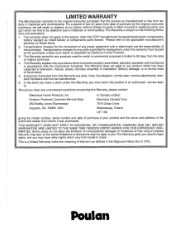
... than EHP manufactured transaxle/transmission components, battery (except as manufactured is free from defects in accordance with the instructions furnished. This Warranty does not apply to locale. Outdoor Products Customer Service Dept. 250 Bobby Jones Expressway Augusta, GA 30909 USA In Canada contact: Electrolux Canada Corp. 7075 Ordan Drive Mississauga, Ontario L5T 1K6 giving the model number, serial number and date of...
... than EHP manufactured transaxle/transmission components, battery (except as manufactured is free from defects in accordance with the instructions furnished. This Warranty does not apply to locale. Outdoor Products Customer Service Dept. 250 Bobby Jones Expressway Augusta, GA 30909 USA In Canada contact: Electrolux Canada Corp. 7075 Ordan Drive Mississauga, Ontario L5T 1K6 giving the model number, serial number and date of...


