
User Manual
Page 1
7 1'1 J OWNER'S MANUAL MODEL NO. HDF550L 5 HP 26 Inch Tiller • Assembly • Operation • Customer Responsibilities • Service and Adjustments • Storage • Troubleshooting • Repair Parts For Parts and Service, contact our authorized distributor: call 1-800-849-1297 For Technical Assistance: call 1-800-829-5886 Poulan 181102 Rev. 2 2.14.02 rad/TR PRINTED IN U.S.A.
7 1'1 J OWNER'S MANUAL MODEL NO. HDF550L 5 HP 26 Inch Tiller • Assembly • Operation • Customer Responsibilities • Service and Adjustments • Storage • Troubleshooting • Repair Parts For Parts and Service, contact our authorized distributor: call 1-800-849-1297 For Technical Assistance: call 1-800-829-5886 Poulan 181102 Rev. 2 2.14.02 rad/TR PRINTED IN U.S.A.
User Manual
Page 2
...8226; After striking a foreign object, stop the unit and disengage the controls quickly. • Never allow adults to make certain all moving parts have stopped. Know how to stop the engine (motor), remove the wire from the plug to prevent accidental starting motors. • Never ...position. • Take all units with the controls and the proper use care when backing. • Never allow bystanders near or under rotating parts. • Exercise extreme caution when operating on slippery surfaces. • Handle fuel with care; exhaust fumes are present, such as specified by...
...8226; After striking a foreign object, stop the unit and disengage the controls quickly. • Never allow adults to make certain all moving parts have stopped. Know how to stop the engine (motor), remove the wire from the plug to prevent accidental starting motors. • Never ...position. • Take all units with the controls and the proper use care when backing. • Never allow bystanders near or under rotating parts. • Exercise extreme caution when operating on slippery surfaces. • Handle fuel with care; exhaust fumes are present, such as specified by...
User Manual
Page 3
... possible dependability and performance. TABLE OF CONTENTS SAFETY RULES PRODUCT SPECIFICATIONS CUSTOMER RESPONSIBILITIES ASSEMBLY OPERATION MAINTENANCE SCHEDULE 2 3 3, 10-12 4-5 6-9 10 SERVICE & ADJUSTMENTS STORAGE TROUBLESHOOTING REPAIR PARTS-TILLER WARRANTY 12-14 15 16 17-22 23 3 It has been designed, engineered and manufactured to service or repair this manual. The instructions will...
... possible dependability and performance. TABLE OF CONTENTS SAFETY RULES PRODUCT SPECIFICATIONS CUSTOMER RESPONSIBILITIES ASSEMBLY OPERATION MAINTENANCE SCHEDULE 2 3 3, 10-12 4-5 6-9 10 SERVICE & ADJUSTMENTS STORAGE TROUBLESHOOTING REPAIR PARTS-TILLER WARRANTY 12-14 15 16 17-22 23 3 It has been designed, engineered and manufactured to service or repair this manual. The instructions will...
User Manual
Page 4
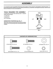
Standard wrench sizes are in the operating position (standing behind tiller handles). To ensure safe and proper operation of those parts left hand is mentioned in this manual, it means when you assemble must be tightened securely. ASSEMBLY Your new tiller ...has been assembled at the factory with exception of yourtiller all parts and hardware you are listed. (1) Utility knife (1) Screwdriver (2) 1/2" wrenches OPERATOR'S POSITION (See Fig. 1) When right or left unassembled for shipping ...
Standard wrench sizes are in the operating position (standing behind tiller handles). To ensure safe and proper operation of those parts left hand is mentioned in this manual, it means when you assemble must be tightened securely. ASSEMBLY Your new tiller ...has been assembled at the factory with exception of yourtiller all parts and hardware you are listed. (1) Utility knife (1) Screwdriver (2) 1/2" wrenches OPERATOR'S POSITION (See Fig. 1) When right or left unassembled for shipping ...
User Manual
Page 15
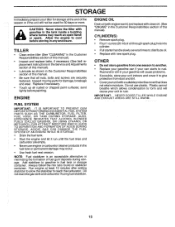
Inspect moving parts for 30 days or more. Add stabilizer to rust. OTHER • Do not store gasoline from dust and dirt. • Cover your unit with a suitable ... distribute oil. • Replace with new spark plug. ENGINE FUEL SYSTEM IMPORTANT: IT IS IMPORTANT TO PREVENT GUM DEPOSITS FROM FORMING IN ESSENTIAL FUEL SYSTEM PARTS SUCH AS THE CARBURETOR, FUEL FILTER, FUEL HOSE, OR TANK DURING STORAGE. Plastic cannot breathe which allows condensation to form and will not be used...
Inspect moving parts for 30 days or more. Add stabilizer to rust. OTHER • Do not store gasoline from dust and dirt. • Cover your unit with a suitable ... distribute oil. • Replace with new spark plug. ENGINE FUEL SYSTEM IMPORTANT: IT IS IMPORTANT TO PREVENT GUM DEPOSITS FROM FORMING IN ESSENTIAL FUEL SYSTEM PARTS SUCH AS THE CARBURETOR, FUEL FILTER, FUEL HOSE, OR TANK DURING STORAGE. Plastic cannot breathe which allows condensation to form and will not be used...

User Manual
Page 17
... Assembly, Reverse 44 181580 Clip 45 73510600 Nut, Hex Keps 3/8-16 NOTE: All component dimensions are given in U.S. KEY PART NO. inches. 1 inch = 25.4 mm 17 NO. NO. MODEL NUMBER HDF550L HANDLE ASSEMBLY 16 2 3 4 3 576f 28 44 7 8 /, .."*"41 /61 29 19 11-20 21 14 ...-j 13 11 10 7 9 4,2 KEY PART NO. DESCRIPTION 1 180814X428 Panel Pnt Control 2 72140512 Bolt, Carriage 5/16-18 UNC x 1-1:2 3 9266R Grip, Handle 4 166376 ...
... Assembly, Reverse 44 181580 Clip 45 73510600 Nut, Hex Keps 3/8-16 NOTE: All component dimensions are given in U.S. KEY PART NO. inches. 1 inch = 25.4 mm 17 NO. NO. MODEL NUMBER HDF550L HANDLE ASSEMBLY 16 2 3 4 3 576f 28 44 7 8 /, .."*"41 /61 29 19 11-20 21 14 ...-j 13 11 10 7 9 4,2 KEY PART NO. DESCRIPTION 1 180814X428 Panel Pnt Control 2 72140512 Bolt, Carriage 5/16-18 UNC x 1-1:2 3 9266R Grip, Handle 4 166376 ...

User Manual
Page 18
... 26 8 29 1 10 1 11 12 13 14 15 25 , 20 1 24)1 114k 23 21 32 16 KEY PART NO. "'' ., . KEY PART NO. Nut Keps Hex 1/4-20 Spring Spacer NOTE: All component dimensions given in U.S. MODEL NUMBER HDF550L BELT GUARD AND PULLEY ASSEMBLY r 7--, ,. • ,4- i"\_,.-7,,24. 4,,.. Cutting *10-24 x 1/2 Type D 4 74610812 Bolt, Hex 1/2-20 x 3/4 5 73660600... Hex 1/4-20 Washer LK Hvy Helical 1/4 Pad, Idler Screw, Set , Socket, Headless C.P. 1/4-20 x 1 /4 Sheave, Engine Pulley, V-Groove, Trans. inches. 1 inch = 25.4 mm 18 NO. REPAIR PARTS TILLER - -
... 26 8 29 1 10 1 11 12 13 14 15 25 , 20 1 24)1 114k 23 21 32 16 KEY PART NO. "'' ., . KEY PART NO. Nut Keps Hex 1/4-20 Spring Spacer NOTE: All component dimensions given in U.S. MODEL NUMBER HDF550L BELT GUARD AND PULLEY ASSEMBLY r 7--, ,. • ,4- i"\_,.-7,,24. 4,,.. Cutting *10-24 x 1/2 Type D 4 74610812 Bolt, Hex 1/2-20 x 3/4 5 73660600... Hex 1/4-20 Washer LK Hvy Helical 1/4 Pad, Idler Screw, Set , Socket, Headless C.P. 1/4-20 x 1 /4 Sheave, Engine Pulley, V-Groove, Trans. inches. 1 inch = 25.4 mm 18 NO. REPAIR PARTS TILLER - -

User Manual
Page 19
... 18 19131311 19 9190R 20 73680600 21 74760516 22 73800500 DESCRIPTION Spring, Stake Bolt, Shoulder Wheel Washer 13/32 x 13/16 x 11 Ga. MODEL NUMBER HDF550L WHEEL AND DEPTH STAKE ASSEMBLY 2 3 flit„„f, ft;„„, f(4.effe 16 17 21 18 9 20 54 ?. ' 20 19 18 7 6 8 '7. 9 10 0 ...rr 13 11 rrrlr 22 15 f 4t) ill < 23 5 A 7 7p54 17 KEY PART NO. Bracket, Wheel Locknut, Crown 3/8-16 Bolt, Hex 5/16-18 x 1 Locknut, w/insert 5/16-18 NOTE: All component dimensions given in U.S. inches. 1 inch = 25.4 mm 19...
... 18 19131311 19 9190R 20 73680600 21 74760516 22 73800500 DESCRIPTION Spring, Stake Bolt, Shoulder Wheel Washer 13/32 x 13/16 x 11 Ga. MODEL NUMBER HDF550L WHEEL AND DEPTH STAKE ASSEMBLY 2 3 flit„„f, ft;„„, f(4.effe 16 17 21 18 9 20 54 ?. ' 20 19 18 7 6 8 '7. 9 10 0 ...rr 13 11 rrrlr 22 15 f 4t) ill < 23 5 A 7 7p54 17 KEY PART NO. Bracket, Wheel Locknut, Crown 3/8-16 Bolt, Hex 5/16-18 x 1 Locknut, w/insert 5/16-18 NOTE: All component dimensions given in U.S. inches. 1 inch = 25.4 mm 19...

User Manual
Page 21
MODEL NUMBER HDF550L TRANSMISSION 2 3 5 6 11 V 14 12 7 7 14 14 8 0 r 15 14 KEY NO. 1 2 3 5 6 7 8 11 12 PART NO. 74760524 74780652 19131311 73800600 9057R428 165835 1948J 74760544 176112 DESCRIPTION Bolt, Hex 5/16-18 x 1-1/2 Gr. 2 Bolt, Hex, Fin 3/8-16 x 3-1/4 Washer... 13/32 x 13/16x 11 Locknut, Hex, w/washer 3/8-16 Shield, Tine Bracket, Engine, R.H. Bracket, Engine, L.H. Bolt, Hex 5/16-18 x 2-3/4 Transmission KEY PART NO. inches. 1 inch = 25.4 mm 21 DESCRIPTION 14 9173R Spacer, Split 15 73970500 Nut Lock Hex Fig 16 19091412 17 19092016 18 10040400 Washer 9/32...
MODEL NUMBER HDF550L TRANSMISSION 2 3 5 6 11 V 14 12 7 7 14 14 8 0 r 15 14 KEY NO. 1 2 3 5 6 7 8 11 12 PART NO. 74760524 74780652 19131311 73800600 9057R428 165835 1948J 74760544 176112 DESCRIPTION Bolt, Hex 5/16-18 x 1-1/2 Gr. 2 Bolt, Hex, Fin 3/8-16 x 3-1/4 Washer... 13/32 x 13/16x 11 Locknut, Hex, w/washer 3/8-16 Shield, Tine Bracket, Engine, R.H. Bracket, Engine, L.H. Bolt, Hex 5/16-18 x 2-3/4 Transmission KEY PART NO. inches. 1 inch = 25.4 mm 21 DESCRIPTION 14 9173R Spacer, Split 15 73970500 Nut Lock Hex Fig 16 19091412 17 19092016 18 10040400 Washer 9/32...
User Manual
Page 23
.... This warranty does not apply to the engine, other rights which have any unanswered questions concerning this product as noted below) orcomponents parts thereof. This Warranty does not apply to any power equipment unit or attachment are belts, tines, tine adapters, normal wear, normal .... This Warranty gives you specific legal rights, and you have been properly assembled, adjusted, operated, and maintained in replacing parts, any products used for parts or labor incurred in accordance with the instructions furnished. Should you may not apply to you have a claim under this ...
.... This warranty does not apply to the engine, other rights which have any unanswered questions concerning this product as noted below) orcomponents parts thereof. This Warranty does not apply to any power equipment unit or attachment are belts, tines, tine adapters, normal wear, normal .... This Warranty gives you specific legal rights, and you have been properly assembled, adjusted, operated, and maintained in replacing parts, any products used for parts or labor incurred in accordance with the instructions furnished. Should you may not apply to you have a claim under this ...


