
User Manual
Page 1
7 1'1 J OWNER'S MANUAL MODEL NO. HDF550L 5 HP 26 Inch Tiller • Assembly • Operation • Customer Responsibilities • Service and Adjustments • Storage • Troubleshooting • Repair Parts For Parts and Service, contact our authorized distributor: call 1-800-849-1297 For Technical Assistance: call 1-800-829-5886 Poulan 181102 Rev. 2 2.14.02 rad/TR PRINTED IN U.S.A.
7 1'1 J OWNER'S MANUAL MODEL NO. HDF550L 5 HP 26 Inch Tiller • Assembly • Operation • Customer Responsibilities • Service and Adjustments • Storage • Troubleshooting • Repair Parts For Parts and Service, contact our authorized distributor: call 1-800-849-1297 For Technical Assistance: call 1-800-829-5886 Poulan 181102 Rev. 2 2.14.02 rad/TR PRINTED IN U.S.A.
User Manual
Page 2
... accessories in safe working condition. • Check shear pins, engine mounting bolts, and other bolts at high speeds on slippery surfaces. • Handle fuel with extreme care. a WARNING A The engine exhaust from the spark plug, thoroughly inspect the tiller for any adjustments while the engine (motor) is in safe working condition. • Never store the machine with the controls and the proper use care when backing. • Never allow...
... accessories in safe working condition. • Check shear pins, engine mounting bolts, and other bolts at high speeds on slippery surfaces. • Handle fuel with extreme care. a WARNING A The engine exhaust from the spark plug, thoroughly inspect the tiller for any adjustments while the engine (motor) is in safe working condition. • Never store the machine with the controls and the proper use care when backing. • Never allow...
User Manual
Page 3
... this manual. IN THE STATE OF CALIFORNIA, A SPARK ARRESTER IS REQUIRED BY LAW (SECTION 4442 OF THE CALIFORNIA PUBLIC RESOURCES CODE). Always observe the "SAFETY RULES". IF A SPARK ARRESTER IS USED, IT SHOULD BE MAINTAINED IN EFFECTIVE WORKING ORDER BY THE OPERATOR. TABLE OF CONTENTS SAFETY RULES PRODUCT SPECIFICATIONS CUSTOMER RESPONSIBILITIES ASSEMBLY OPERATION MAINTENANCE SCHEDULE 2 3 3, 10-12 4-5 6-9 10 SERVICE & ADJUSTMENTS STORAGE TROUBLESHOOTING REPAIR PARTS-TILLER WARRANTY 12...
... this manual. IN THE STATE OF CALIFORNIA, A SPARK ARRESTER IS REQUIRED BY LAW (SECTION 4442 OF THE CALIFORNIA PUBLIC RESOURCES CODE). Always observe the "SAFETY RULES". IF A SPARK ARRESTER IS USED, IT SHOULD BE MAINTAINED IN EFFECTIVE WORKING ORDER BY THE OPERATOR. TABLE OF CONTENTS SAFETY RULES PRODUCT SPECIFICATIONS CUSTOMER RESPONSIBILITIES ASSEMBLY OPERATION MAINTENANCE SCHEDULE 2 3 3, 10-12 4-5 6-9 10 SERVICE & ADJUSTMENTS STORAGE TROUBLESHOOTING REPAIR PARTS-TILLER WARRANTY 12...
User Manual
Page 4
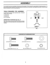
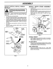
... Bolts 5/16-18 x 1-1/4 (6) Lock Washers 5/16 (4) Washers 3/8 x 7/8 x 14 0 (6) Hex Nuts 5/16-18 4 ASSEMBLY Your new tiller has been assembled at the factory with exception of yourtiller all parts and hardware you are listed. (1) Utility knife (1) Screwdriver (2) 1/2" wrenches OPERATOR'S POSITION (See Fig. 1) When right or left unassembled for shipping purposes. Use the correct tools as necessary to insure proper tightness. TOOLS REQUIRED FOR ASSEMBLY A socket wrench set...
... Bolts 5/16-18 x 1-1/4 (6) Lock Washers 5/16 (4) Washers 3/8 x 7/8 x 14 0 (6) Hex Nuts 5/16-18 4 ASSEMBLY Your new tiller has been assembled at the factory with exception of yourtiller all parts and hardware you are listed. (1) Utility knife (1) Screwdriver (2) 1/2" wrenches OPERATOR'S POSITION (See Fig. 1) When right or left unassembled for shipping purposes. Use the correct tools as necessary to insure proper tightness. TOOLS REQUIRED FOR ASSEMBLY A socket wrench set...
User Manual
Page 5
... width may be adjusted to better suit operator. (See "HANDLE HEIGHT" in the Service and Adjustments section of cartoning material. Repeat foropposite side. FIG. 2 5 Tightenallhardware securely. • Cut cable ties securing tiller to skid and remove tiller from skid. • Remove screws securing depth stake to engine brackets with bolts, lock washers and nuts. If it INSTALL DEPTH STAKE ASSEMBLY Loosen nut "A". • Insert stake support between engine bracket halves with...
... width may be adjusted to better suit operator. (See "HANDLE HEIGHT" in the Service and Adjustments section of cartoning material. Repeat foropposite side. FIG. 2 5 Tightenallhardware securely. • Cut cable ties securing tiller to skid and remove tiller from skid. • Remove screws securing depth stake to engine brackets with bolts, lock washers and nuts. If it INSTALL DEPTH STAKE ASSEMBLY Loosen nut "A". • Insert stake support between engine bracket halves with...

User Manual
Page 6
... controls and adjustments. OPERATION KNOW YOUR TILLER READ THIS OWNER'S MANUAL AND SAFETY RULES BEFORE OPERATING YOUR TILLER. Save this manual for future reference. FORWARD TINE CONTROL - DEPTH STAKE - Used when starting a cold engine. Learn and understand their meaning. Controls engine speed. 6 Engages tines in forward direction. RECOIL STARTER HANDLE - F FNRA / \ STOP \ / TILLING FORWARD NEUTRAL REVERSE CAUTION ENGINE OR WARNING ON ENGINE OFF FAST SLOW CHOKE FUEL OIL RUN STOP O FORWARD TINE CONTROL REVERSE TINE CONTROL...
... controls and adjustments. OPERATION KNOW YOUR TILLER READ THIS OWNER'S MANUAL AND SAFETY RULES BEFORE OPERATING YOUR TILLER. Save this manual for future reference. FORWARD TINE CONTROL - DEPTH STAKE - Used when starting a cold engine. Learn and understand their meaning. Controls engine speed. 6 Engages tines in forward direction. RECOIL STARTER HANDLE - F FNRA / \ STOP \ / TILLING FORWARD NEUTRAL REVERSE CAUTION ENGINE OR WARNING ON ENGINE OFF FAST SLOW CHOKE FUEL OIL RUN STOP O FORWARD TINE CONTROL REVERSE TINE CONTROL...

User Manual
Page 7
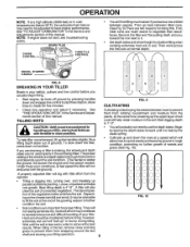
... motion to enable the tines to desired position. Change depth stake to penetrate the ground. Replace the hairpin clip and clevis pin. • For normal tilling, set depth stake at the second or third hole from the top. ENGINE • Move throttle control to "STOP" position. • Never use choke to operate all controls before starting your tiller and while tilling. Also, the more the...
... motion to enable the tines to desired position. Change depth stake to penetrate the ground. Replace the hairpin clip and clevis pin. • For normal tilling, set depth stake at the second or third hole from the top. ENGINE • Move throttle control to "STOP" position. • Never use choke to operate all controls before starting your tiller and while tilling. Also, the more the...
User Manual
Page 8
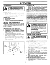
...). • Pull recoil starter handle quickly. Pull recoil starter handle until the fuel lines and carburetor are empty. AROUNDTOWN • Disconnect spark plug wire. • Drain fuel tank. • Transport in "DISENGAGED" position when starting engine. FILL ENGINE WITH OIL (See Fig. 7) • With engine level, remove engine oil filler plug. • Fill engine with other hand. Use fresh, clean, regular unleaded gasoline. (Use of overflowing. Drain the gas tank, start of compression cycle (rope will increase carbon and lead oxide deposits and reduce valve life.) IMPORTANT...
...). • Pull recoil starter handle quickly. Pull recoil starter handle until the fuel lines and carburetor are empty. AROUNDTOWN • Disconnect spark plug wire. • Drain fuel tank. • Transport in "DISENGAGED" position when starting engine. FILL ENGINE WITH OIL (See Fig. 7) • With engine level, remove engine oil filler plug. • Fill engine with other hand. Use fresh, clean, regular unleaded gasoline. (Use of overflowing. Drain the gas tank, start of compression cycle (rope will increase carbon and lead oxide deposits and reduce valve life.) IMPORTANT...
User Manual
Page 9
..., the slower the engine and tine speed needed. First, wide turns are two reasons for proper tilling. Tines will dig with throttle in the fall, remove vines and long grass to be adjusted for five minutes. • Check tine operation and adjust if necessary. Then work across the first cuts at fast speed the tiller will help tiller move forward, lift up the handles slightly (thus...
..., the slower the engine and tine speed needed. First, wide turns are two reasons for proper tilling. Tines will dig with throttle in the fall, remove vines and long grass to be adjusted for five minutes. • Check tine operation and adjust if necessary. Then work across the first cuts at fast speed the tiller will help tiller move forward, lift up the handles slightly (thus...
User Manual
Page 10
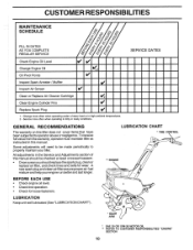
... year you should replace the spark plug, clean or replace air filter, and check tines and belts for loose fasteners. A new spark plug and clean airfilter assure proper air-fuel mixture and help your tiller. FILL IN DATES AS YOU COMPLETE REGULAR SERVICE 4, -\.. -N.. .. ,4/ ,r);, 4/ 4/ SERVICE DATES Check Engine Oil Level V V Change Engine Oil Oil Pivot Points V19,2 V Inspect Spark Arrester / Muffler V, Inspect Air Screen V Clean or Replace Air Cleaner Cartridge f1/ 2' Clean Engine Cylinder Fins V Replace Spark Plug V 1 - All adjustments in high ambient temperatures...
... year you should replace the spark plug, clean or replace air filter, and check tines and belts for loose fasteners. A new spark plug and clean airfilter assure proper air-fuel mixture and help your tiller. FILL IN DATES AS YOU COMPLETE REGULAR SERVICE 4, -\.. -N.. .. ,4/ ,r);, 4/ 4/ SERVICE DATES Check Engine Oil Level V V Change Engine Oil Oil Pivot Points V19,2 V Inspect Spark Arrester / Muffler V, Inspect Air Screen V Clean or Replace Air Cleaner Cartridge f1/ 2' Clean Engine Cylinder Fins V Replace Spark Plug V 1 - All adjustments in high ambient temperatures...
User Manual
Page 11
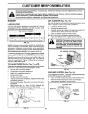
... Disconnect spark plug wire before performing any maintenance (except carburetor adjustment) to prevent accidental starting the engine and after every 25 hours of operation or at least once a year if the tiller is on oil. Remove fuel from running low on level surface. • Oil will result in increased oil consumption when used in the Operation section of this manual. ENGINE LUBRICATION Use only high quality detergent oil rated with oil. AIR CLEANER CARTRIDGE COVER AIR CLEANER SCREW FIG...
... Disconnect spark plug wire before performing any maintenance (except carburetor adjustment) to prevent accidental starting the engine and after every 25 hours of operation or at least once a year if the tiller is on oil. Remove fuel from running low on level surface. • Oil will result in increased oil consumption when used in the Operation section of this manual. ENGINE LUBRICATION Use only high quality detergent oil rated with oil. AIR CLEANER CARTRIDGE COVER AIR CLEANER SCREW FIG...
User Manual
Page 12
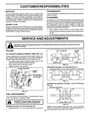
... a spark arrester screen assembly, remove every 50 hours for your unit unless the gasket area around the transmission and the engine muffler, air filter and carburetor are sharp. of all foreign matter. • Keep finished surfaces and wheels free of use. Select handle height best suited for cleaning and inspection. ENGINE BRACKETS HANDLE PANEL NUTS (ALSO 2 ON LEFT SIDE OF TILLER) 0. Water in tine shaft. SERVICE AND ADJUSTMENTS a CAUTION: Disconnect spark plug wire from spark plug and...
... a spark arrester screen assembly, remove every 50 hours for your unit unless the gasket area around the transmission and the engine muffler, air filter and carburetor are sharp. of all foreign matter. • Keep finished surfaces and wheels free of use. Select handle height best suited for cleaning and inspection. ENGINE BRACKETS HANDLE PANEL NUTS (ALSO 2 ON LEFT SIDE OF TILLER) 0. Water in tine shaft. SERVICE AND ADJUSTMENTS a CAUTION: Disconnect spark plug wire from spark plug and...
User Manual
Page 13
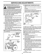
... both belts and location of all belt guides and rests on cable only enough to service belts. Belt guard must be removed to relieve spring tension. Be sure belt is "OFF" (up). SERVICE AND ADJUSTMENTS TINE OPERATION CHECK (See Fig. 19) a WARNING: Disconnect spark plug wire from unit. • Replace belt guard by reversing above procedure. Be sure slot in the "OFF" (up ), push down on idler pulley. • Before installing reverse (outside) V-belt, turn belt "inside...
... both belts and location of all belt guides and rests on cable only enough to service belts. Belt guard must be removed to relieve spring tension. Be sure belt is "OFF" (up). SERVICE AND ADJUSTMENTS TINE OPERATION CHECK (See Fig. 19) a WARNING: Disconnect spark plug wire from unit. • Replace belt guard by reversing above procedure. Be sure slot in the "OFF" (up ), push down on idler pulley. • Before installing reverse (outside) V-belt, turn belt "inside...
User Manual
Page 15
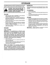
...; Drain the fuel tank. • Start the engine and let it to give protection from one season to another. • Replace your gasoline can if your unit indoors and cover it run until the fuel lines and carburetor are securely fastened. CYLINDER(S) • Remove spark plug. • Pour 1 ounce (29 ml) of oil through spark plug hole into cylinder. • Pull starter handle slowly several times to distribute oil. • Replace with clean oil. (See "ENGINE...
...; Drain the fuel tank. • Start the engine and let it to give protection from one season to another. • Replace your gasoline can if your unit indoors and cover it run until the fuel lines and carburetor are securely fastened. CYLINDER(S) • Remove spark plug. • Pour 1 ounce (29 ml) of oil through spark plug hole into cylinder. • Pull starter handle slowly several times to distribute oil. • Replace with clean oil. (See "ENGINE...
User Manual
Page 16
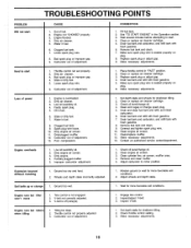
... runs but tiller won't move 1. Throttle control not properly adjusted. 3. Adjust wheels and depth stake. 1. Carburetor out of adjustment. 1. See "TO START ENGINE" in fuel. 6. Replace spark plug or adjust gap. 9. Throttle control not set properly. 2. Dirty air cleaner. 3. Low oil level/dirty oil. 4. Oil in "FAST" position. 2. Drain fuel tank and refill with fresh gasoline. 7. Check oil level/change oil. 2. Drain and clean fuel tank and refill, and clean carburetor. 6. Make necessary adjustments. 13. Dirty engine. 4. Remove and clean muffler. 5. Engine runs...
... runs but tiller won't move 1. Throttle control not properly adjusted. 3. Adjust wheels and depth stake. 1. Carburetor out of adjustment. 1. See "TO START ENGINE" in fuel. 6. Replace spark plug or adjust gap. 9. Throttle control not set properly. 2. Dirty air cleaner. 3. Low oil level/dirty oil. 4. Oil in "FAST" position. 2. Drain fuel tank and refill with fresh gasoline. 7. Check oil level/change oil. 2. Drain and clean fuel tank and refill, and clean carburetor. 6. Make necessary adjustments. 13. Dirty engine. 4. Remove and clean muffler. 5. Engine runs...

User Manual
Page 17
REPAIR PARTS TILLER - - NO. DESCRIPTION 13 72140506 Bolt, Carriage 5/16-18 x 3/4 Gr. 5 14 181452X428 Panel,Handle 16 166377 Handle, R.H. 18 166868 Cable, Control, Tine 19 151229 Lever, Control, Tine 20 154805 Pin, Pivot 21 12000027 Ring, Klip 28 19131312 Washer 13/32 x 13/16 x 12 Ga. 29 12000059 Retaining, Ring 43 180528 Cable Assembly, Reverse 44 181580 Clip 45 73510600 Nut, Hex Keps 3/8-16 NOTE: All...
REPAIR PARTS TILLER - - NO. DESCRIPTION 13 72140506 Bolt, Carriage 5/16-18 x 3/4 Gr. 5 14 181452X428 Panel,Handle 16 166377 Handle, R.H. 18 166868 Cable, Control, Tine 19 151229 Lever, Control, Tine 20 154805 Pin, Pivot 21 12000027 Ring, Klip 28 19131312 Washer 13/32 x 13/16 x 12 Ga. 29 12000059 Retaining, Ring 43 180528 Cable Assembly, Reverse 44 181580 Clip 45 73510600 Nut, Hex Keps 3/8-16 NOTE: All...

User Manual
Page 18
... Bolt, Hex 3/8-16 x 1-3/4 10 156705X428 Guard, Belt 11 19091016 Washer 9/32 x 5/8 x 16 Ga. 12 104213X Nut, Cap 1/4-20 13 72140406 Bolt, Carriage 1/4-20 x 3/4 14 133035 V-Belt (Forward Motion) 15 2614J V-Belt (Reverse) 16 12000028 Ring, Retainer 17 2649M Key, Square 18 151236 Pulley, Flat, Trans. KEY PART NO. MODEL NUMBER HDF550L BELT GUARD AND PULLEY ASSEMBLY r 7--, ,. • ,4- "'' ., . DESCRIPTION 1 180377 Assembly, Bracket, Belt Guard 2 9484R Clip, Cable 3 86777 Screw, Hex, Washer Hd., Slotted, Thd. REPAIR PARTS TILLER...
... Bolt, Hex 3/8-16 x 1-3/4 10 156705X428 Guard, Belt 11 19091016 Washer 9/32 x 5/8 x 16 Ga. 12 104213X Nut, Cap 1/4-20 13 72140406 Bolt, Carriage 1/4-20 x 3/4 14 133035 V-Belt (Forward Motion) 15 2614J V-Belt (Reverse) 16 12000028 Ring, Retainer 17 2649M Key, Square 18 151236 Pulley, Flat, Trans. KEY PART NO. MODEL NUMBER HDF550L BELT GUARD AND PULLEY ASSEMBLY r 7--, ,. • ,4- "'' ., . DESCRIPTION 1 180377 Assembly, Bracket, Belt Guard 2 9484R Clip, Cable 3 86777 Screw, Hex, Washer Hd., Slotted, Thd. REPAIR PARTS TILLER...

User Manual
Page 19
... 22 73800500 DESCRIPTION Spring, Stake Bolt, Shoulder Wheel Washer 13/32 x 13/16 x 11 Ga. NO. 1 9194R 2 74760520 3 74760512 4 73220500 5 10040500 6 73800600 7 4921H 8 1952J 9 122233X 10 326J 11 74780628 13 1951J DESCRIPTION Pin, Clevis Bolt, Hex 5/16-18 x 1-1/4 Bolt, Hex 5/16-18 x 3/4 Nut, Hex 5/16-18 Washer, Lock 5/16 Locknut, w/washer 3/8-16 Clip, Hairpin Support, Depth Stake, R.H. MODEL NUMBER HDF550L WHEEL AND DEPTH STAKE...
... 22 73800500 DESCRIPTION Spring, Stake Bolt, Shoulder Wheel Washer 13/32 x 13/16 x 11 Ga. NO. 1 9194R 2 74760520 3 74760512 4 73220500 5 10040500 6 73800600 7 4921H 8 1952J 9 122233X 10 326J 11 74780628 13 1951J DESCRIPTION Pin, Clevis Bolt, Hex 5/16-18 x 1-1/4 Bolt, Hex 5/16-18 x 3/4 Nut, Hex 5/16-18 Washer, Lock 5/16 Locknut, w/washer 3/8-16 Clip, Hairpin Support, Depth Stake, R.H. MODEL NUMBER HDF550L WHEEL AND DEPTH STAKE...

User Manual
Page 21
NO. inches. 1 inch = 25.4 mm 21 Bolt, Hex 5/16-18 x 2-3/4 Transmission KEY PART NO. Washer 9/32 x 1-1/4 x 16 Ga Washer, Lock 1/4 • 19 74610412 Bolt, Hex 1/4-28 x 3/4 Gr. 5 20 Engine, Briggs Model 126402 Order parts from engine manufacturer NOTE: All component dimensions given in U.S. REPAIR PARTS TILLER - - MODEL NUMBER HDF550L TRANSMISSION 2 3 5 6 11 V 14 12 7 7 14 14 8 0 r 15 14 KEY NO. 1 2 3 5 6 7 8 11 12 PART NO. 74760524 74780652 19131311 73800600 9057R428 165835 1948J 74760544...
NO. inches. 1 inch = 25.4 mm 21 Bolt, Hex 5/16-18 x 2-3/4 Transmission KEY PART NO. Washer 9/32 x 1-1/4 x 16 Ga Washer, Lock 1/4 • 19 74610412 Bolt, Hex 1/4-28 x 3/4 Gr. 5 20 Engine, Briggs Model 126402 Order parts from engine manufacturer NOTE: All component dimensions given in U.S. REPAIR PARTS TILLER - - MODEL NUMBER HDF550L TRANSMISSION 2 3 5 6 11 V 14 12 7 7 14 14 8 0 r 15 14 KEY NO. 1 2 3 5 6 7 8 11 12 PART NO. 74760524 74780652 19131311 73800600 9057R428 165835 1948J 74760544...
User Manual
Page 23
... locale. Transportation charges for any parts submitted for replacement under this Warranty, you have been properly assembled, adjusted, operated, and maintained in replacing parts, any product which have any products used for the movement of any power equipment unit or attachment are belts, tines, tine adapters, normal wear, normal adjustments, standard hardware and normal maintenance. 6. Please refer to the engine, other rights which vary from...
... locale. Transportation charges for any parts submitted for replacement under this Warranty, you have been properly assembled, adjusted, operated, and maintained in replacing parts, any product which have any products used for the movement of any power equipment unit or attachment are belts, tines, tine adapters, normal wear, normal adjustments, standard hardware and normal maintenance. 6. Please refer to the engine, other rights which vary from...


